Skulina Hlif Kjartansdottir
How to make [almost] anything
Week 8: Computer-Controlled-Machining
This week we will learn about computer controlled-machining. This is our agenda for the week.
Week 8: Assignment
The assignment for this week is to make something big. We will be designing our own "big project", learning how to transfer the 3D design over to a 2D drawing (.ai, .dxf, .pdf), adjusted in the VCarve software to be ready to be cut in the big milling machine - The Shopbot. For this we will use one sheet of sheet of plywood - 15mm in thickness, size: 1220 x 2440 mm.
We wathced an interesting introduction of atfab.co – design company that designs furniture. They share their design on the open desk website. I took some inspiration from this and several other sites, that are introducing furniture design created with computer-controlled-machining.
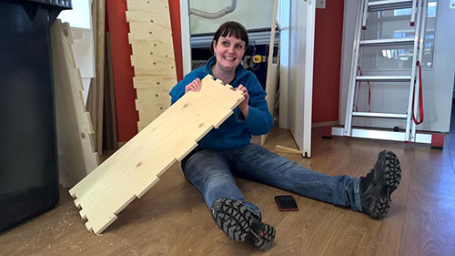
I started a design for a stand-desk that I could use as an "alternative" desk, as sitting for long hours is not so healthy for our bodies. The design is simple and the stand-desk is not meant to be adjustable for height. It is a "stop-by desk" and to reinforce this colored flowers are to be cut and inserted into the desktop in order to encourage me not to stay for too long at the desk and to remind me of the lure of nature outside the office.
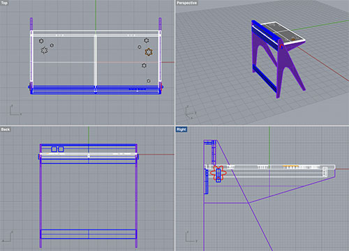
The modelling was carried out in Rhino. The stand-desk is a moderate size, with space for the computer and some papers and a book on either side. The design incorporates sockets for electricity at the top, with joints of simple incised pockets and supportive rails going between the legs. The construction should press-fit and hold the table-top and side-legs in place.

The modelling was mostly problem free, but I ran into some issues with surfaces and closure, but resolved this with capping and tweeking the parameters of tolerance. I also redesigned some parts of the model.
The Rhino files were imported into the VCarve software as a .dxf file (or alternatively saved as an .ai file first when needed). Each part of the 3D model was saved separately for this purpose and layed out flat in the eventual cutting position - see Stand_bord_04_Redesign2_Arranged.3dm.
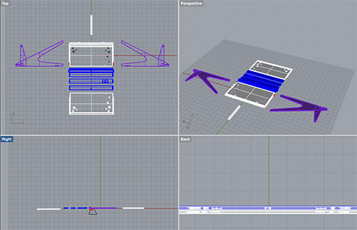
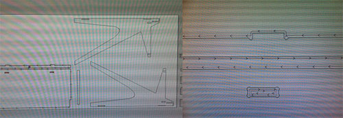
The individual .dxf files were then imported to VCarve Pro: Import - Import vectors. Each part was selected by drawing a square around it with the mouse – and moved onto the sheet, which had the size pre-set. At this point I had to select the parts and rescale them as the model was modelled in cm – from 100% to 1000%. The double lines were then cleaned up - deleted and excess lines also removed. When this had been accomplished lines had to be joined into shapes and "dogbones" or "filetbones" inserted where needed (tool radius: 3.175 mm), to ensure that the tool would cut correctly into corners, creating clearance in internal corners when a slot is the same size as the tool.
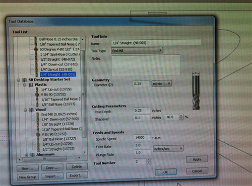
Then a tool (1/4" Straight (48-005), toolpaths and feeds (3.0 inch/sec) and spindle speeds (14000 r.p.m.) had to be assigned. Finally the file was exported, ready for the milling on The Shopbot.

During this project we worked on the Shopbot machine in pairs of two, to support each other in learning the ropes and to assist if needed. I helped a collegue, Gudbjorg, to carry out the milling of her project, a cupboard. It turned out to be a good fit and she was a happy person on completion.
We were supported by a Icelandic wiki on using the ShopBot and a shopbot fablab wiki shopbot fablab wiki. There is the Router Bit Basics for CNC - A compilation of the Wisdom and Knowledge of ShopBot Forum Members is a helpful resource for tackling tools and processes for milling on a grand scale.
When all parts of the model had been cleaned up and setting adjusted (the extra lines deleted) in VCarvePro the file was exported and taken over to the computer in the Shopbot room. In VCarve - Transform object - Move selection, and the Z zero was set at the bootom in lower left corner of the sheet. Then recalculate toolpaths: Tools - Recalculate all toolpaths and save the toolpaths on the control computer.
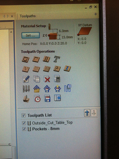
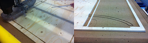
The sheet is screwed down in each corner with a small block on the side to give clearance ad to line the sheet with the edge on The Shopbot. On the Shopbot and control computer the work procedures are as follows:
Set z axis 0 to the sacrificial layer
Set x and y to corner of sheet
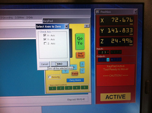
Cut part – open toolpaths
Chose file
Enter key in machine
Put on goggles
Hit the start button
The machining of the two parts completed in the first round was successful. Care can be taken to support or push down lightly the parts that are cut lose from the sheet.
Plans for next Week
Learn how to use the Shopbot - and cut the design.
Notes
My Notes from this week.