Skulina Hlif Kjartansdottir
How to make [almost] anything
Week 18: Project Development
This week we are working on our final project, finalising the concept, working out design issues and developing. The agenda was:
Complete your final project, tracking your progress:
- what tasks have been completed, and what tasks remain?
- what has worked? what hasn't?
- what questions need to be resolved?
- what will happen when?
- what have you learned?
Documentation during development
Demand- vs supply-side time management
Spiral development
Week 18: Assignment
This week the assignment is to make a create a prototype and try to finalise the design.
I had a delayed delivery of my materials for casting as the shipment got lost in translation, but they did finally arrive, much later than expected. The shipment included Ignite® Fluorescent Color Pigments, Smooth-Cast® 321 ultra-low viscosity/low cost casting resins, and the Clear Flex 50 uruthene rubber. While waiting for the goods the design and making of the flower case for "Flower2Sound" project was carried out.
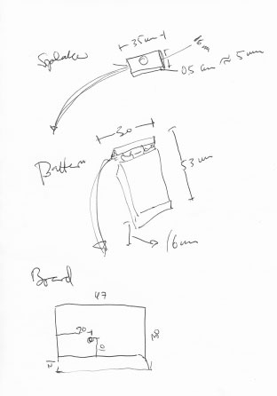
I began by sketching and measuring for the electronics, that were to be encased:
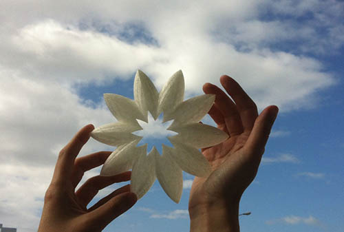
These lines were duplicated to create 2 sets for working separately on the the 2 halves of the flower form. On the top part a Curve Boolean operation was carried out to create a cut-out form in the centre of the shape to let the light into the case:
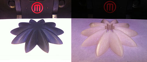
I decided to print the bottom parts for the flower form, but also did one transparent print for the top part. The material is PLA (polylactic acid), a bio-degradable polymer produced from lactic acid, which can be fermented from crops such as maize.
The mould making started with a modelling session in Rhino from the original forms to create, first a mould of those and later a 3D Rhino mould that would be machine-cut on the Shopbot. The modelling therefore happened in three stages:
I cut out a frame for the mould out of acryllic plastic that would hold the silicone rubber in place while it would set in the mould. I then calculated the volume in preparation for mixing the Oomoo*25.
I built on my former experience with electronics and produced 3 boards, with a photoresistor, ATtiny45 microcontroller, battery connector and a speaker, all to be contained within the flower forms.
flower2sound from Skulina Kjartansdottir on Vimeo.
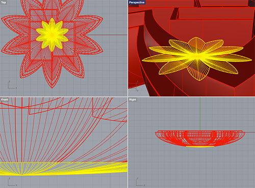
Design in Rhino
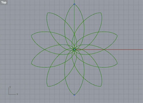
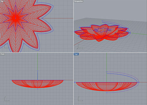
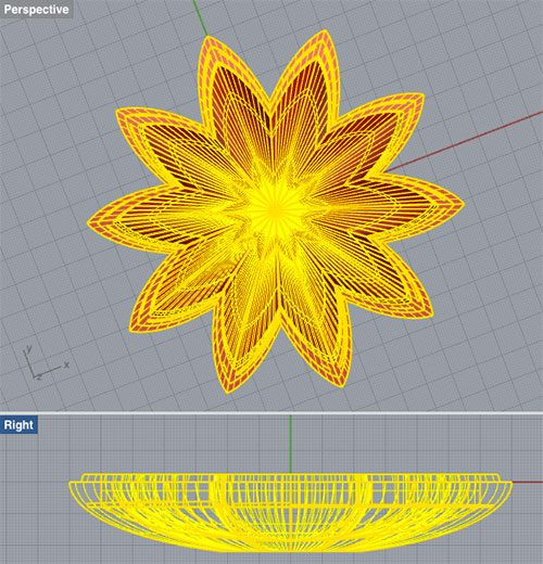
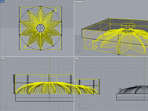
I created the flower pedal shape with an elipse and pulled one point out of it at the top end. Then I did a Transform – Array –Polar (by 8) to create the basic shape, that became the skeleton of the form:
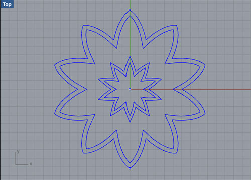
Then an elipse was drawn across end points of the flower shape and segmented by quadrants (splitted). The outer lines of the flower shape were offset to create the wall thickness ( 5 and 3 mm) for the bottom and top parts:
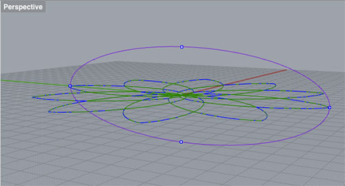
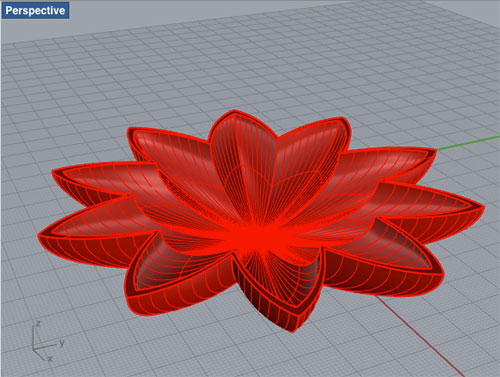
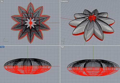
A revolved shape was made from these curves. A problem arose with the revolve because the revolve axis was not matching the offset line. This was corrected by offsetting the inner flower shape line again to match. On second attempt the revolve did not succeed because of the condition that the “control points for path curve cannot be on revolve axis”. I then mirrored the revolve curves on the axix and could create the surface for the bottom part of the form:
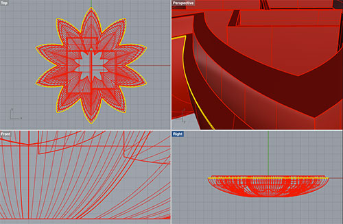
This was repeated for the outer wall and the two surfaces were meant to be lofted to create a solid shape. I noticed that the surface mesh created for the two parts was different in that the inner shape was more dense than the outer shape. Lofting did not happen, as “some but not all of the curve end points touch”. This could have occurred because the revolve curve was offset from the original one. I therefore drew another elipse, segmented the curve to have a similar curve as the first one. This curve, and a previous one that was an orginal as well, was used to create 2 new surfaces with the Rail Revolve command and those appeared to have a similar amount of splines. These could be joined with Cap Planar Holes command to join the surfaces and create a solid.
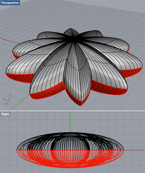
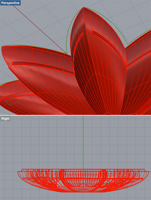
This had to be done in 2-3 steps as the top edges turned out to not align. At this point a design decision was made to scale the whole model down to 140 mm width, in order to for it to fit for 3D printing and to be able to create a mould out of the millable wax we had in the lab.
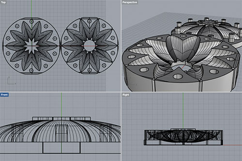
A square box was made to correct this with a Boolean operation, and the botton part moved up to match the x axis. This solid was then mirrored to create to top shape:
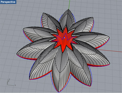
A cylinder was made from the small inner curve from the Boolean operation to cut the opening of the top shape:
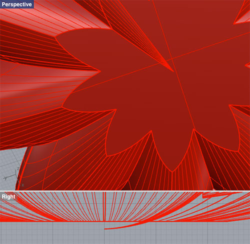
The bottom part now required an extra ridge to be added on the inside of the rim. This was created from curves of the edge.
In the bottom part of the form a set of boxes was created to hold the board, speaker and a battery and they were later trimmed to fit snugly into the bottom shape.
On a close inspection of a model it turned out that I had made a mistake in a Boolean Union action, with the result that bits were sticking out of the bottom part of the model.
Various actions/commands were tried to remedy this, such as extruding surfaces, deleting the bits standing out and trying to patch the holes. What worked in the end was to delete the holes that were inside a plane, then using untrim surface and cutting the surfaces again to the right size.
The workaround for this was:
Select all parts of the model – Join.
Hide model – and delete all extra model.
Show
Explode (exploded the model into 198 parts)
Select horizontally, from left to right, the faces that needed to be removed (this selects only the faces that are contained within that area).
Delete the faces.
Select the whole part.
Join - Then the 156 surfaces were joined into one open polysurface.
Solid Edit Tools – Holes – Delete Holes and select the edge of the hole in question. This mends the face and makes a continuing surface of the face.
Explode the whole model again.
Surface – Surface Edit Tools – Untrim Border.
This created extra faces at the top and bottom of the model. I made a visual Notes of those:
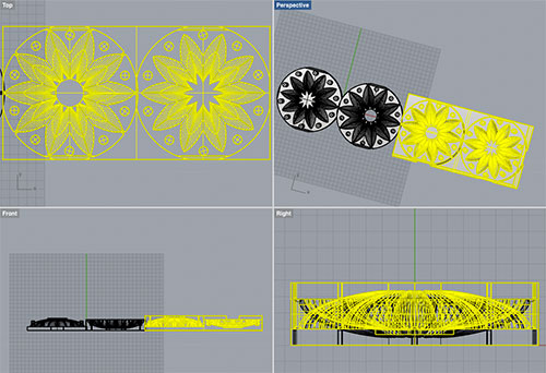
I used the selection tool to select all the surfaces and execute the Trim Border command in one go for all faces. Then I selected all and joined 155 surfaces into 3 open polysurfaces – bottom, the boxes and the outside shell. An Edit Split (the outside shell) – selected the cutting object (the red line at the bottom and the upper rim) and pressed Enter. The bottom faces and uneccessary top faces could be selected separately and deleted.
For the bottom part:
For the top part:
I was then able to select all – Ctrl A and Join. The command joined the 3 surfaces into one open polysurface. This completed the modeling of the flower and its two parts. The intention was to 3D print the bottom part of the form, but to cast the top part adding photochromic pigments to the resins or uruthene rubber.
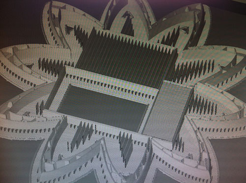
3D Printing
The Rhino 3dm file was saved in the .stl format for 3D printing. It was then opened in the MakerBot software and the settings adjusted before selecting the Replicator2 printer and exporting the printfile. During this process the printing stages can be visually evaluated, by sliding through the form to be printed. Presets can at this stage be adjusted. I did make some changes as some of the areas did not seem to be supported properly (with clicking bridges).
Some problems rose during printing with threads coming lose and creating a discontinuation in the print. This was resolved by gluing the threads in place with a glue gun and readjusting settings in the software.
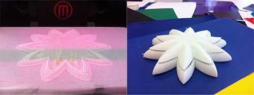
I did print both the top and bottom forms in white, clear and black PLA - to see how this would match my castings later on.
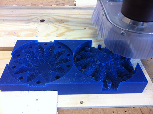
Mould-Making
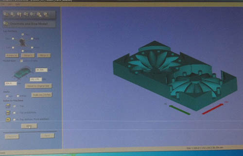
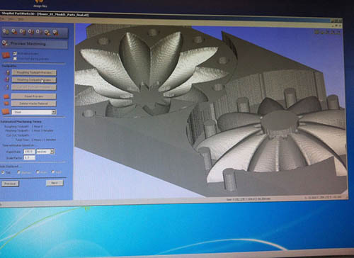
The Rhino .stl file was then opened in PartWorks 3D to calculate toolpaths, set the position of xy and height, and to chose the tool, a four flute 1/8 inch for the roughing path as well as for the finishing path. The toolpaths are saved onto the workstation.
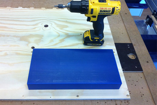
The Shopbotting preparation was done in various stages, first by fastening the block of wax.
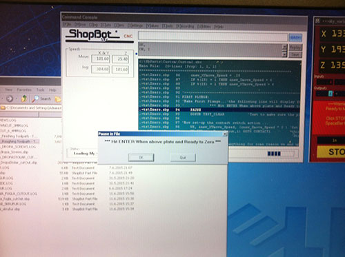
Then, the various settings in the Shopbot control interface are set, to set the tool position in relation to the wax block and the work ahead.
The cutting is carried out, first the rough cutting and then the finishing cut, that made the mould quite smooth in preparation for casting.
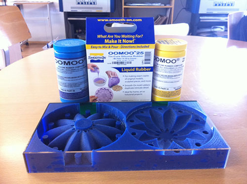
Casting
In Rhino select Analyse – mass properties – volume.
Part1: Volume = 346331.63 (+/- 0.079) cubic millimeters
Part2: Volume = 467414.903 (+/- 0.017) cubic millimeters
In total: 813746 cubic millimeters. Converting this to liters makes 0.81
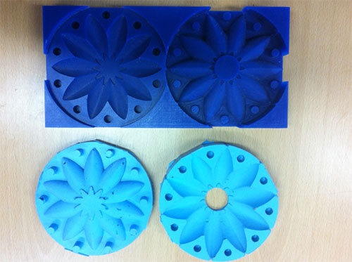
Oomoo25 silicone rubber compound was now used to create the mould.
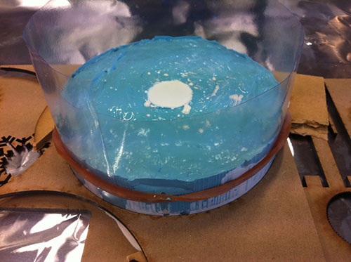
The mould was then surrounded with clear plastic to prevent leakage and a hydrostone top cast made for testing.
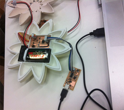
Electronics, Coding and Testing
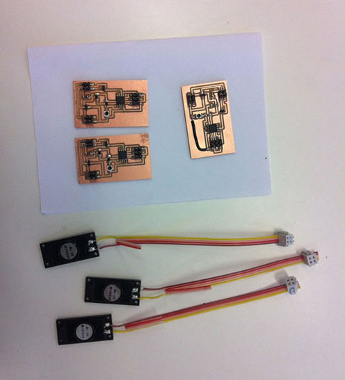
When fully packed the forms contained a 6V battery and a speaker that were connected to the board:
I then started coding and experimenting with the sound output:
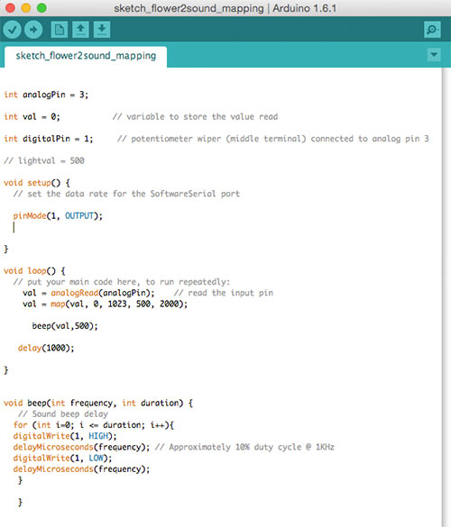
I adopted my code from the networking session code, by taking out the code relevant to the input board, because on the boards that I am using for the final project, the input (from the phototransistor) and the output (speakers) are on the same board. The resulting code was this:
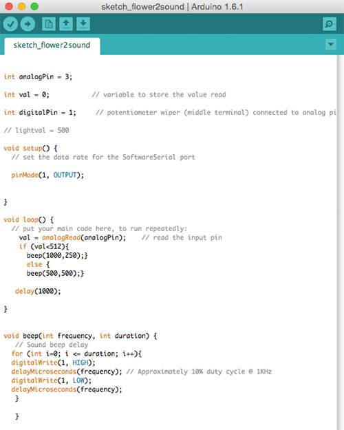
When having established that the code worked, that the phototransistor was reading light and an output (beep) was established from the speakers, I employed Arduino mapping and entered the following line to the code:
val = map(val, 0, 1023, 0, 255);
This established a mapping function that enabled sound of different frequency to be produced according to the variable input (light). The resulting code was as follows:
The sound varied in frequency when the flower2sound was exposed to infra-red LED light in testing.
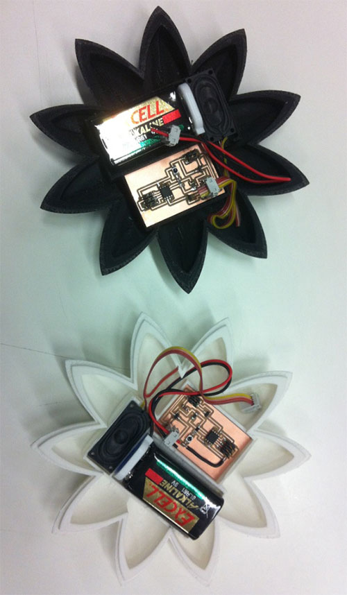
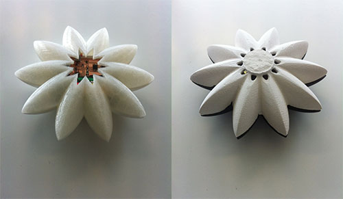
I managed to complete a set of two forms during the time available on the course for the final project:
Although I did not manage to reach all my project goals I feel quite confident in keeping on with its development and look forward to carry on with my experiments in the near future.
Future Plans
To carry on experimenting with the photochromic materials and coding, as well as to expand on the potential and variety that can be achieved with this idea and the lessons learned during prototyping.
Notes
My Notes from this week.