Skulina Hlif Kjartansdottir
How to make [almost] anything
Week 13: Networking and Communications
This week we will be working with electronics and code in order to learn about networking and communications. This is our agenda for the week.
Week 13: Assignment
The assignment for this week is to to design and build a wired and/or wireless network connecting at least two processors. I decided ot use light and sound to communicate, in preparation for my project, and used my input and output board for testing the communication. We started this week with a programming lesson, as most of us little prior knowledge of programming, where we identified the structure of a sketch and the main commands. We did this programming exercise in Arduino and created a test sketch:
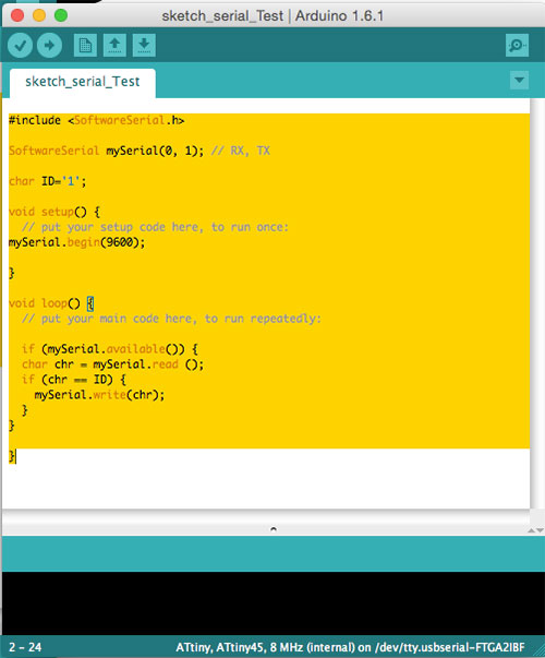
We looked up information on aspect of programming, such as the Py Serial documentation , the Arduino references / tutorials and guidelines or tutorials on programming, like Tiny AVR Programmer Hookup Guide.
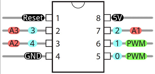
I checed the layout and pins for the microcontrollers of my boards and where to connect for different paths of communication:
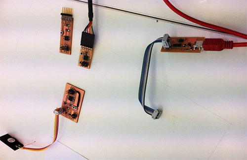
On starting the input and output boards were assembled and connected to the computer:
I copied commands from the example to start the networking sketch: #include
SoftwareSerial mySerial(10, 11); // RX, TX
into the parameter section. I wrote: mySerial.begin(4800); into the void section. I then wrote: if (mySerial.available())
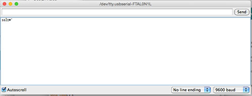
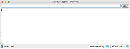
mySerial.write(mySerial.read()); into void loop. I started the Serial Monitor and set the baud to 9600. Typing a letter in the "Send" field resulted in a return of a letter in the larger window, but if a string of letters was typed only the first letter would appear.
Next, the following code was entered:
if (mySerial.available()) {
char chr = mySerial.read ();
if (chr == ID) {
mySerial.write(chr);
}
}
}
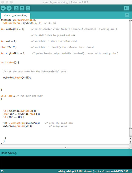
char ID='1' was a unique identifier, that identified the input board. The script for this "reader of light" was (1) when your name is called, read the light (2) then tell the reading. In figuring out the meaning of the code, I noted the following:
if (mySerial.available()) { - have I heard something
char chr = mySerial.read (); - I have heard something and written it down
if (chr == ID) { - checking if the content of read is meant for the microcontroller. If this is true the actor will do everything contained within the curly braces
val = analogRead(analogPin); // read the input pin
mySerial.println(val); // debug value – returning the message
Hook-up wires were now connected to the input board – pin1 to TX. Nothing happened. A line of code was taken out: pinMode(1, OUTPUT);
On opening the serial monitor and entering the number 1, it now returned a reading of the light.
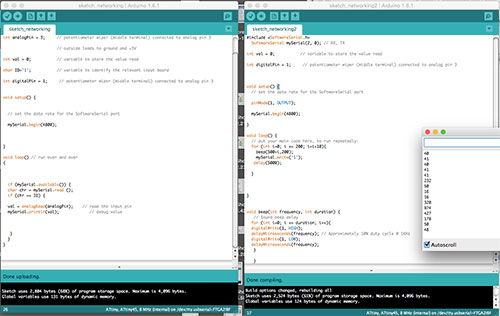
This code was compiled and uploaded. The sketch then looked like this:
The script for the output board was then programmed. The intention was to:
1. Call input1
2. Ask for reading from input1
3. Receive reading from input1
4. Respond to the intensity of light, by decreasing or increasing sound tone.
This code was written and MySerial set to:
SoftwareSerial mySerial(0, 2); // RX, TX – on input1
SoftwareSerial mySerial(2, 0); // RX, TX – on output/Master
void beep() {
// Sound beep delay
for (int i=0; i <= 200; i++){
digitalWrite(1, HIGH);
delayMicroseconds(500); // Approximately 10% duty cycle @ 1KHz
digitalWrite(1, LOW);
delayMicroseconds(500);
}
}
void lowbeep() {
// Sound beep delay
for (int i=0; i <= 100; i++){
digitalWrite(1, HIGH);
delayMicroseconds(1000); // Approximately 10% duty cycle @ 1KHz
digitalWrite(1, LOW);
delayMicroseconds(1000);
}
}
1. instead of making beep fixed, at 1 Khz – I changed it to be flexible (500+i).
2. interval between tone steps, going from interval of 1 to interval of 10
Frequency and duration can now be controlled and changed.
For connecting the two boards – adding: mySerial.write('1');
This will request response from the input1.
Then this code was entered:
for (int i=0; i <= 200; i=i+10)
int – i=0; starts at 0 – this is done as long as the i is smaller or equal to 200; determines how fast are this going to go.
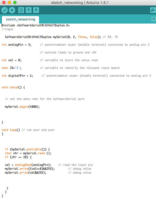
The sketch for input1 then was like this:
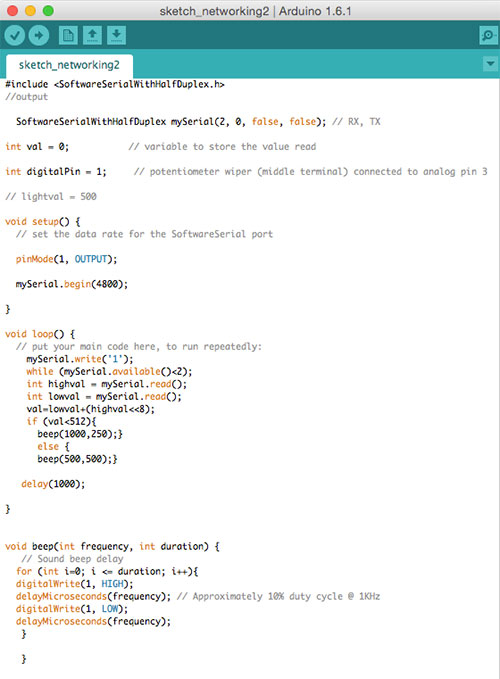
The sketch for output board was:
The program was uploaded to both boards – input and output
On the output board – I checked the Serial Monitor to see if reading was taking place. It did.
To work with the reading of values the intervals of reading needed to be defined and the plan became to have the speaker playing a certain tone, if the reading was below or beyond a certain value in the light reading.
Plans for next Week
Study more programming and the Arduino references.
Notes
My Notes from this week.