Electronics Design
Designing with EAGLE
Get the freeware here
EAGLE (Easily Applicable Graphical Layout Editor) is a flexible and expandable EDA schematic capture, PCB layout, autorouter and CAM program. EAGLE is popular among hobbyists because of its freeware license and rich availability of component libraries on the web. Also exist the Hello Fab Library especially made for this assignment.
To start with Eagle watch this tutorial
Hello board files
First you can download the Hello Echo schematic, board files and the Fab library here
Circuit Design
Second go to the zip file and extract it, then copy it and go to the Library folder into the Eagle’s folder and paste it there.
Open the schematic board with Eagle and now you can add the necessary components to the board with the Fab’s Library that you have to load on Eagle, just go to Library on the menu bar and activate it.
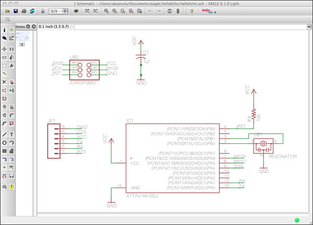
This is the view that will appear once you open it. The Schematic in electronics is a drawing representing a circuit. It uses symbols to represent real-world electronic components. The most basic symbol is a simple conductor (traces), shown simply as a line. If wires connect in a diagram, they are shown with a dot at the intersection.
This is the view that will appear once you open it. The Schematic in electronics is a drawing representing a circuit. It uses symbols to represent real-world electronic components. The most basic symbol is a simple conductor (traces), shown simply as a line. If wires connect in a diagram, they are shown with a dot at the intersection.
I checked these web pages to know more about theory and components
-6-pin programming header.
-microcontroller: attiny44A.
-FTDI header.
-20MHz resonator.
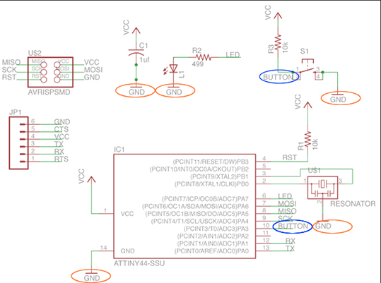
I added the next components:
-Resistor (value 10k)
-Button (OMERON switch)
-Ground
-VCC
-LED
-Resistor (value 499 ohms)
Once you have the necessary components for the circuit you proceed on the schematic view to organize them according the components specifications and uses, then you label and linked them with the default components on the board.
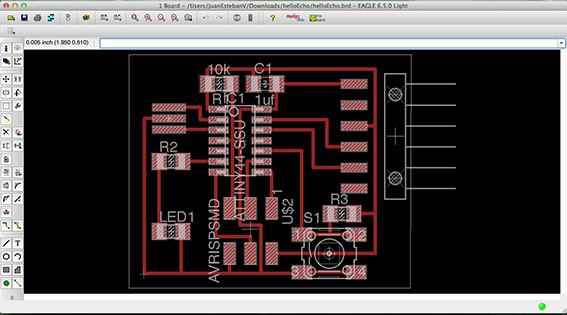
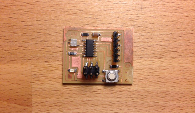
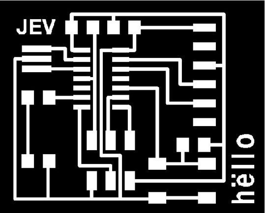
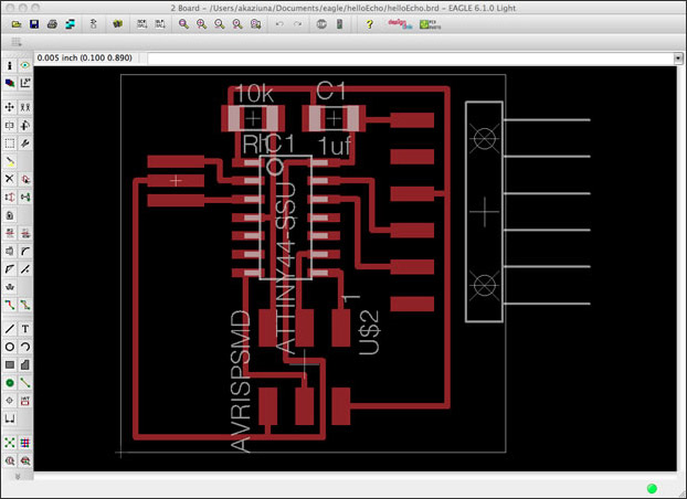
Then organize them on the Lay out as you prefer, take care with the thicknesses of the connections because when you are milling, the track of the bit could be not enough and the copper line get damage.
The next step is mill it, so export the file as a PNG and open it in a image editor to create the cut outline. Make sure that is at least 20 pixels width outside the cut outline. Have a look to the fourth week assignment of my web page to see how to cut the board on the Roland Modela and soldering the components: