

Output Devices
Designing the Board
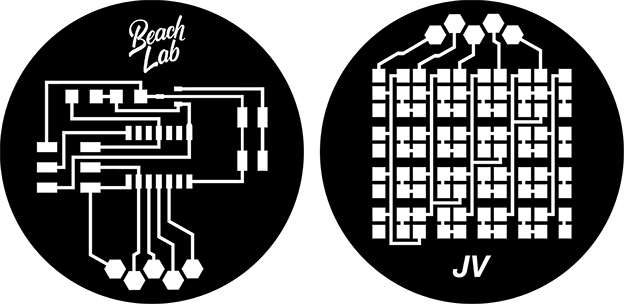
This week I want to try doing something with Charlieplexing LED array method, that consist in the use of the 3-state logic capabilities of microcontrollers that allows multiple circuits to share the same output line or lines. I want to use it in the future for the Fab Lab Sitges front window and make an interactive display for the curios people that have a look to the inside.
First step is to design your circuit, I am based on the existing examples of Neil which is 5 x4 LED array.
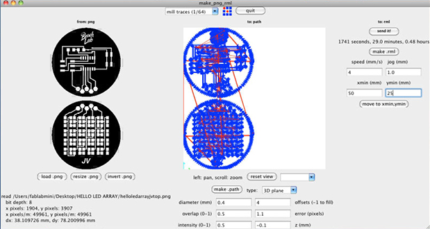
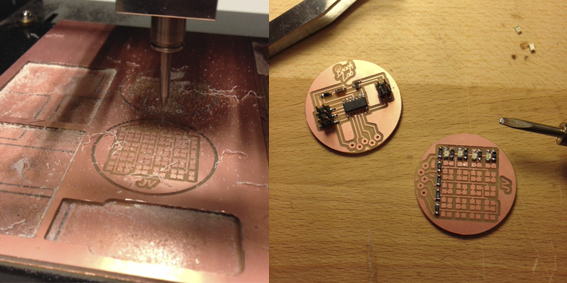
Second step is milling and soldering, I used the Roland Modela with 1/64 to do the traces and 1/32 for the holes and cut the board.
these boards has a lots of components so be patient and take your time. I soldered from left to right and I fixed first one point of the components by rows to then finish the second point, this trick saved me a lot of time. At last check with the tester if the connections are working and with the magnifying glass if are proper soldered, I had to correct a couple of LED’s but if I did not I would have burnt it once will be plug to the power.
Third step is programing, I started from scratch with Arduino IDE and the Help of Andrew Leek. The program is very basic and easy; I defined the 5 pins I am using and as a constant that they are outputs. Then I used Digital Write for all the pins to turn on/off (LOW/HIGH) and the Delay variations of time, the code below has a Delay of 5. But you can play with the delay you want.
Smoke Test
I designed the board based on a existing Neil’s example, so First I smoke tested the board to see if it is correct the position of the Diod and do not burn the whole board.
I checked with the battery on the correct position at first and did not burn, so was ok. But we wanted to see some smoke so I inverted the position and a bit of smoke and happened what had to happen; Diod fried!
Finally I changed the Diod and uploaded the program, but the fifth row of LED’s are not working. I checked with the tester all the connections and seems it is ok, I checked with the zoom glass the LED’s solder and is fine and I checked the program and seems is ok too. Son finally Does not work but looks great at least the other four rows.
Get all the files here
The Code
/* Attiny44a Charlieplexing Output Device by Juan Esteban Vallejo / 2014 (with help from Andrew Leek) */ // constants won't change. // They're used here to set pin numbers: const int ledPin1 = 1 ; // the number of the LED pin const int ledPin2 = 2 ; // the number of the LED pin const int ledPin3 = 3 ; // the number of the LED pin const int ledPin4 = 4 ; // the number of the LED pin const int ledPin5 = 5 ; // the number of the LED pin // initialize variables: void setup() { // initialize the LED pin as an output: pinMode(ledPin1, OUTPUT); pinMode(ledPin2, OUTPUT); pinMode(ledPin3, OUTPUT); pinMode(ledPin4, OUTPUT); pinMode(ledPin5, OUTPUT); } void loop(){ digitalWrite(ledPin1, HIGH); delay(5); digitalWrite(ledPin2, HIGH); delay(5); digitalWrite(ledPin3, HIGH); delay(5); digitalWrite(ledPin4, HIGH); delay(5); digitalWrite(ledPin5, HIGH); delay(5); digitalWrite(ledPin5, LOW); delay(5); digitalWrite(ledPin4, LOW); delay(5); digitalWrite(ledPin3, LOW); delay(5); digitalWrite(ledPin2, LOW); delay(5); digitalWrite(ledPin1, LOW); delay(5); }
Final Project Application
The lighting system of the RGB concreted Lamp was designed to work as a Output device in networking regulated by two inputs. The inputs idea is to dim ligth intensity and change colors, for this I am using two potentiometers. There are five Output devices which four are rows of five RGB LED’s and one that only has one RGB LED, this one is on charge of the communication between all.
I designed the Boards using Eagle, and all the components are from the Fab Inventory so if you want to make yours have a look to the list below and the fab inventory. Just in case to double check info updates of the components because the list is constantly being updated.
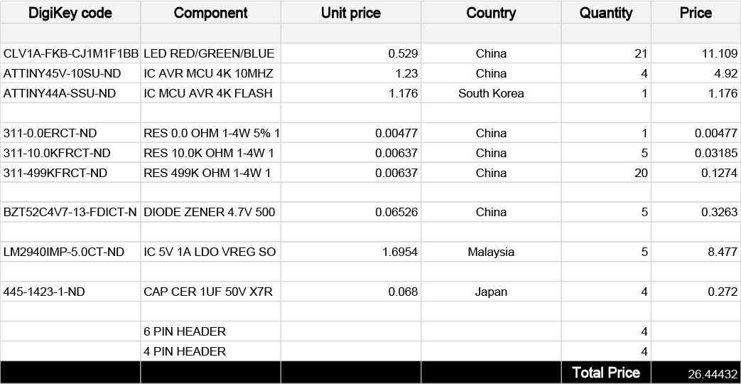
The RGB LED’S used work with 5V and there is a power regulator of 4.7V that protects the components in case to receive more power than the accepted. The LED’s are using 499 resistor for green and blue color, and for red color two 499 resistor one over the other to cruze them and create the half of the power that requires. Programing is made through the 6 PIN HEADER and Power, RX and TX with the 4 PIN HEADER.
Then I proceed to mill them with the Roland Modela using bits of 1/64 for traces and 1/32 for cut it, once were ready I soldered all the boards and then they were ready to program.
For programing the four lighting boards I am using Arduino IDE, the program consist in turn on/off the RGB game of colors (white, red, green, blue, yellow, cyan, magenta) and one set that fades the whole color game.
So the boards function when they are connected to the power, but they were designed to be slaved by the bridge which has connected the power supply, and two potentiometers that one dims the light intensity and other for change the color set program.
The ATTINY 45 Node Code
/* Attiny45a co. nod rgb led lighting system
created 2014
by Juan Esteban Vallejo (with Andrew Leek)
*/
#include
The circuits are going to be connected in networking slaved by the main board that receives input commands, so I used the SoftwareSerial library that allows serial communication to define the RX TX. Inputs are analog potentiometers, the turning is divided by the number of steps that the program requires. First dims the light from 0 which is off to highest light intensity and second change to 7 seven colors.
All the functions I want to have in the Lamp exceeds the microprocessor memory, so my colleague Andrew Leek advised me to run the program with a variable modifier from Arduino called PROGMEN to save memory and run a lighter program.
I declared the pins RGB LED colors are using and then used the next code to define the colors I want the LEDs combination produce (red, green, blue, cyan, magenta, yellow, white), this action is saving enough memory to have the rest of the program.
PROGMEM prog_uchar color_table[6][3] = { {1, 1, 0}, {0, 1, 0}, {0, 1, 1}, {0, 0, 1}, {1, 0, 1}, {1, 0, 0} };
The ATTINY 44 Bridge Code
/* Attiny44a co. bridge networking 1 rgb led
created 2014
by Juan Esteban Vallejo (with Andrew Leek)
*/
#include
Summering both codes do the same program, what changes is the microprocessors (ATTINY 44/45): -Change the light intensity -Change to 7 different RGB colors -Turn ON/OFF
Conclusions
At this point of the course I learnt how to use Eagle and electronic design basic circuits devices, apart of soldering which surprised me the times I am spending now to solder the components, I consider now I have good soldering skills. I have learnt a lot of programing in the Arduino IDE environment, I still require help but I know what I need is to get more use to the languages used and logic. The most important thing I learnt is to know what to research in case get stuck in something; weeks ago I even had no idea what to look for on internet, so that is what it makes me more happy, I can jump these barriers already.