
Input Devices
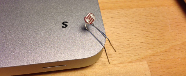
For this week assignment I’m going to use a Photoresistor sensor, which is possibly one of the sensor I am going to use in my final project. First I want to see how it works and if it really is what I need for my project. So I am going to test it and will see.
Designing the board
I redesigned the board based on Neil’s example. I am using a different Photoresistor so I changed the layout of the board and also add a 0 resistor because I need to bridge the wires. My idea is to put the board outside and test the sunlight. I will add double face tape to could paste it on a wall and leave the sensor working to check it during different hours.

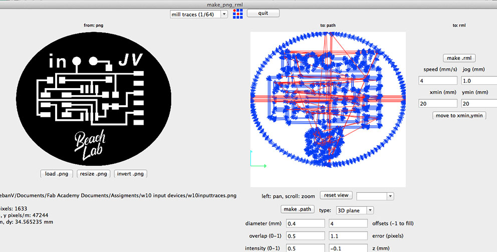
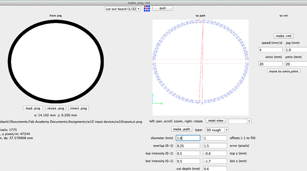
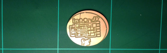
Then I mill the board with the Roland Modela, for traces I am using a 1/64 bit and to cut I am using a different bit because our 1/32 is broken.
So I changed the the diameter of the 1/32 which is 0.79 to 1.6 instead. Also during the use the machine with this bit we realized that it is better to put the speed to 1 instead of 4 because there is so much stress for the bit and the resolution is better like this.
I made a mistake with the cut .png, I changed the cutting edge making it bigger and when I load the png in fab modules I should have changed the x 3mm to the left to compensate the what I increased in the edge. So that is the looking of my board, fortunately was big enough and did not cut the traces.
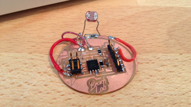
Then I soldered the board, but when I was trying to programing it something was going wrong on the Arduino interface I realized that I had some mistakes and problems on the traces, I saw it with the help of Francisco my tutor. We checked everything and we found the solution so I had to jump with wires the mistakes and then it worked.
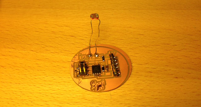
My board finally look like this.
With the board fixed I proceed to program it, my first idea was to put this board outside to check the sunlight at different hours, but this photosensor is not for this immediately reads the highest value, there are some that are made especially for this task. So by the moment I can check the interior light intensity.
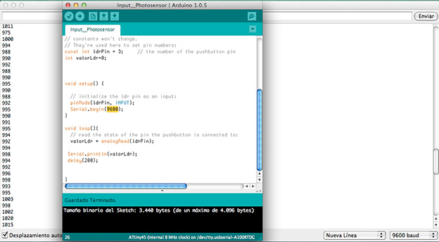
#include