|
Week 7: Computer-controlled machining
The assignment for this week was to make something big using the CNC milling machine.
CNC machine in Aalto Fablab
In Aalto Fablab we have a CNC machine from Digima. The cutting area is 120 cm by 120 cm. The software which is controlling the machine is called Nc studio and the tool paths can be prepared in Surfcam.
Pretesting
To start I got a piece of 12 mm plywood to experiment the hinge structure. I designed the lines in illustrator, exported it as a .dxf file and opened the .dxf file in Surfcam. There I made the tool paths, made the code and saved it as .nc file. Then I opened the .nc file in NC studio. I had already fixed the plywood on the machine bed using the double sided tape and clamps. Using NC studio I set the origin and I started to cut.
Pretest results
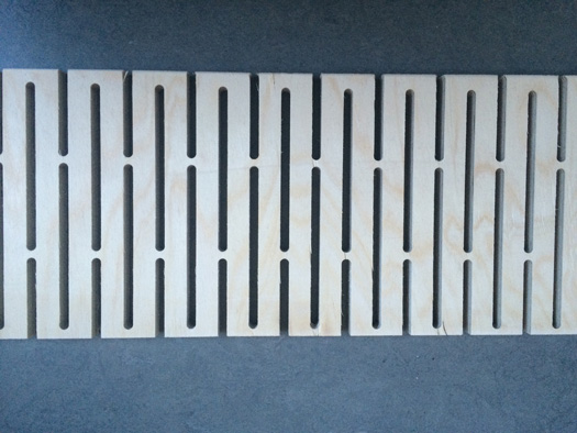
The hinge structure worked. The plywood was bending nicely. In the design, I set the distance between two vertical lines on top of each other, 1 cm and the distance between the two adjacent vertical lines in parallel, 2cm. After cut I measured these lengths again. The former was 0.4 cm and the latter was 1.4 cm. This showed that the cut width with a 6 mm drill bit is 3 mm. The cut width is important to be known. In closed shapes there is a possibility to select either inside or outside of the shape. When there is a line it selects either right side or left side of the line. It doesn't cut on the line.
Trying to bend 12 mm plywood
Preparing the tool path in Surfcam
After opening the file, NC should be selected from the top menu. In NC if the design has two dimensions, 2 Axis should be selected. Then the instructions at the left bottom corner should be followed.
As an example, I pressed on Auto and then visible. Doing this the paths will be selected. Then done and again done. After that there is gonna be a dialogue box to ask you if you wanna have your tool path inside or outside your shape. Selecting the inside, the outcome will be smaller than the actual size related to the drill bit. For example, using 6 mm drill bit, 3 mm will be removed.
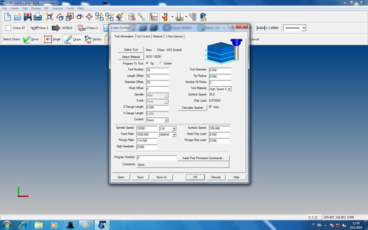
Tool information settings in Surfcam
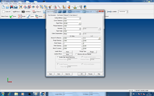
Cut control settings in Surfcam
For making the code readable by Nc studio (.nc) code, operation manager should be clicked. After that clicking on the Post button will create the code. This code should be saved with (.nc) extension that can be opened later in Nc Studio.
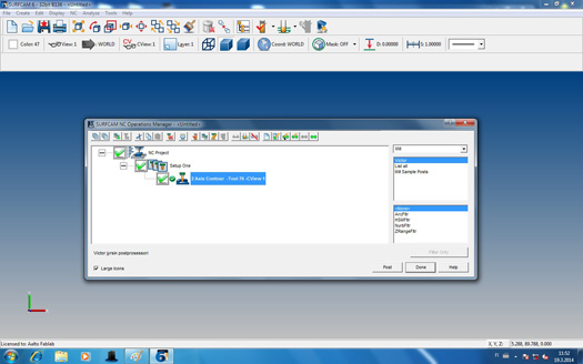
Making the code with (.nc) extension in Surfcam
Setting the origin and starting the cut in NC studio
Having the .nc file ready in surfcam, it can be opened in Nc studio. The code is visible in the right window. On the top of right window there is a manual botton, that the origin can be set using that. For setting the origin you bring the drill bit where you like and then on the up right side where X, Y and Z are shown, click on x and y. Another dialogue box will be open that you select yes. Now you have set X and Y as origin.
For setting the Z you need to put the metal part which is attached to the front of the machine with a spiral wire. Put it under the drill bit and click on mobile calibrator from the Operation menu. After that you can first simulate and if everything was fine, click again on the simulation button that it stops and start the main task.
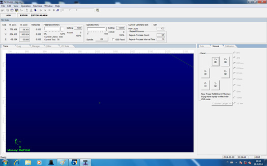
Nc studio view
Table having Alvar Aalto design
I would like to make a table and put it under my TV which is mounted on the wall. This table can be used to put my laptop on. I adore Alvar Aalto's design so in this exercise I decided to use one his designs for my table. First I got the design I was interested in and manually traced it in illustrator using the pencil tool. Then I used the smooth tool to make the paths more smooth. The final shape was not 100% the same as the original but it was very close. I wanted to cut two of these pieces for the top and the bottom of the table and for the side I use the hinge structure that follow the main shape in the top and buttom.
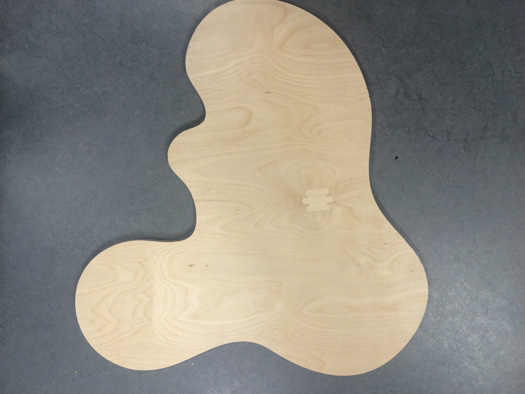
Table top

Trying to bend 4 mm plywood
Challenges
I would like to use some joints to attach the side to the top and the bottom. I found several joints online and making them was not problem. The shape that I chose was curvy and the sides were bendable wood so I did not know where to put the joints that they match. I looked for some illustrator plugins that I can measure the curve length with them but did not work for me.
Later I found out that there is a possibility to measure the curve in Autocad. Also in Autocad, it is possible to divide a shape into same length subdivisions.
The other challenge I was facing was fixing the board on the bed. I was using some double sided tape, but could not hold the piece on the bed. I added some clamps to hold the piece better.
The drill bit on the machine was an upcut drill bit and especially when I was cutting the 4 mm plywood, the ply was moving upwards.
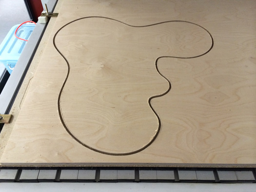
Table top on the machine bed
Finally I decided to change the plan for this exercise and hold the table with legs. The legs are not closed shapes. There is a 12 mm gap between the side holding the top of table and the side holding the bottom of the table.
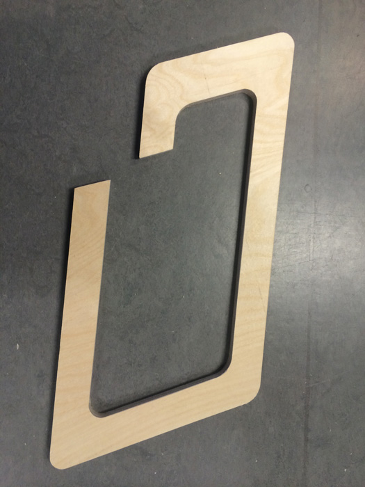
Table leg
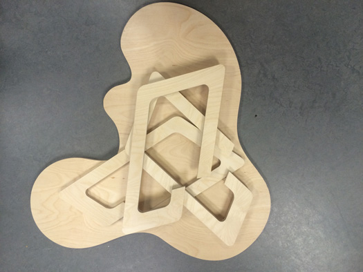
Table with the legs
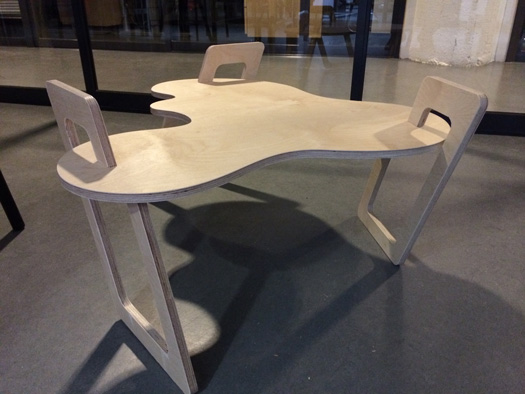
Table
The legs can be put in different locations and the table was tested if it could hold about 7 kilos
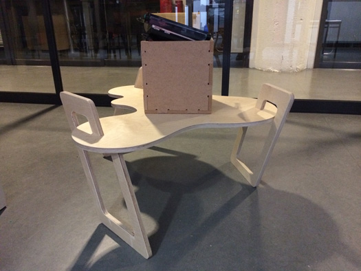
Table holding something heavy
Files:
Bending plywood
Leg
Table top
|
 Fab Academy Class 2014