|
Week 10: Input Devices
This week assignment was design a board having a sensor and measure something. There were some examples already in Neil's keynotes that were good for a start. I tired the temperature sensor, switch and the microphone. Finally I designed a board for a phototransistor and measured the changes in the ambient light with that.
The experiment with the microphone.
Experimenting with the microphone, I just reproduced the board Neil had already done. Example for the electret microphone. All of the files needed for making the board and programming it, can be found under the Sound section of this webpage.
First I made the board, soldered the components and tried to program it. When I attached the FTDI cable, the usb port was shutting itself. I realised that I have some shorts in my circuit. It was exactly in my FDTI connector. I desoldered it, shortened the pins on the soldering part and re-soldered it. The problem was fixed and I could program the microcontroller.
Note: the electret microphone has a negative and a positive pin. The negative pin connected the body of the microphone from. If you look at the back of the microphone, there is a small pcb with and two pins which are sticking out. One of the pins is protected with a circle from the PCB and the other one has a circle which is open in some points and let the pin attach to the PCB.
The negative pin of the electret microphone can be tested with a multimeter too. If you attach one probe of the multimeter to the negative pin and the other one to the body, the multimeter should show no resistance.
In the following there are the pictures of the board and how it reacts to the sound. It was also needed to install pySerial to be able to run the .py files. In this tutorial there is a good explanation about the whole process.
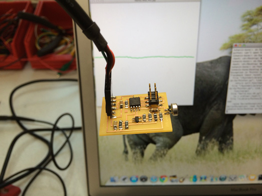
Board with a electret microphone
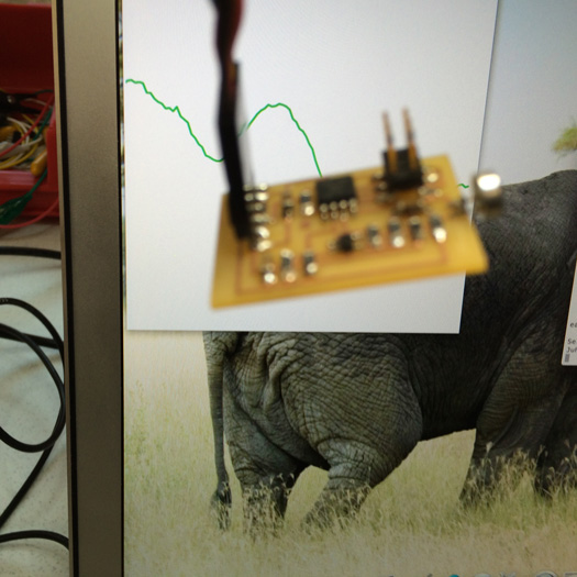
Board with a electret microphone recognising sound.
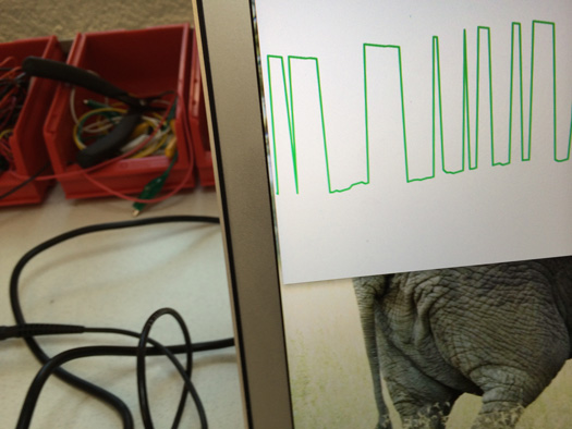
Board with a electret microphone recognising sound.
Phototransistor sensor
For the phototransistor sensor I first designed the board in eagle, then made the board using the modela milling machine and soldered the components.
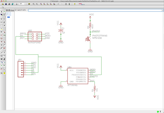
Schematics
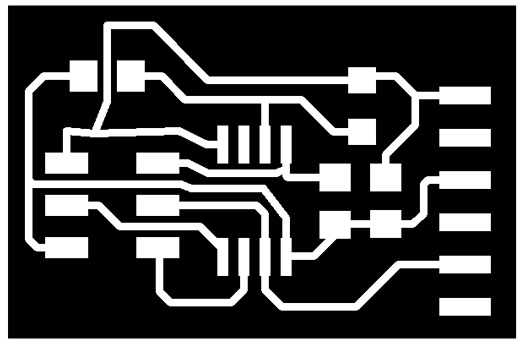
Board traces
Then I downloaded the files hello.light.45.c, hello.light.45.make and hello.light.45.py from Neil's keynotes.
Connecting the board via an FTDI cable to the computer and attaching it to the fabISP, I programed the board by using the command "sudo make -f hello.light.45.make program-usbtiny"in the terminal. Note to be in the directory that the file exists before executing these commands.

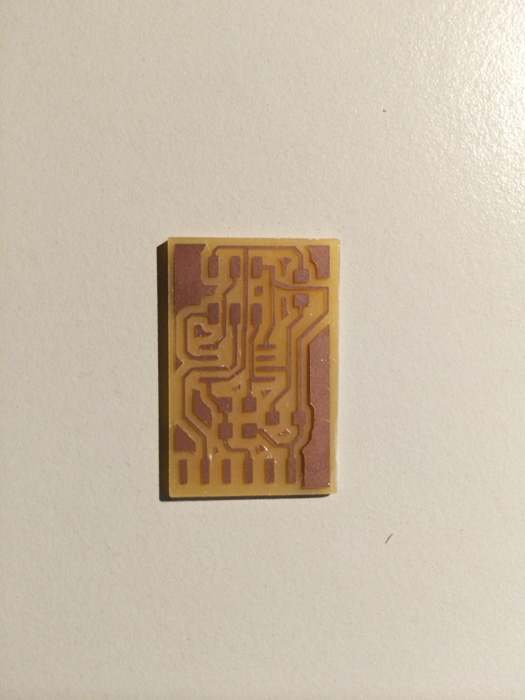
Board interior
Board for phototransistor sensor
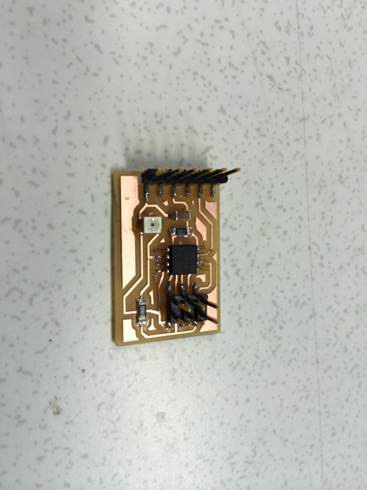
Board for phototransistor sensor with all the components
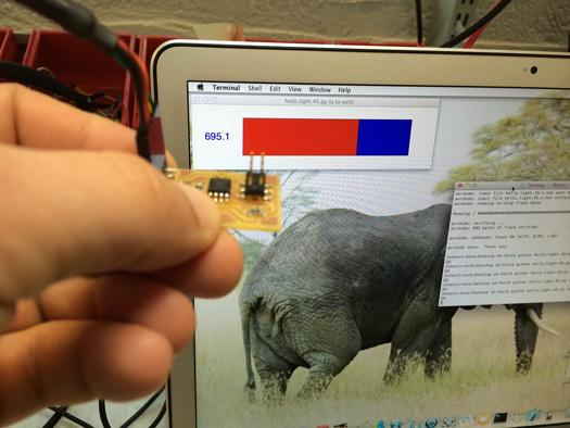
For running the .py file, the serial port to which the board is connected should be known. Using mac I used the command ls /dev/tty.usb* to find out which serial port my board is attached to. For me it was /dev/tty.usbserial-FTFA7VQO.
Then using the command "python hello.light.45.py /dev/tty.usbserial-FTFA7VQO" I ran the .py file.
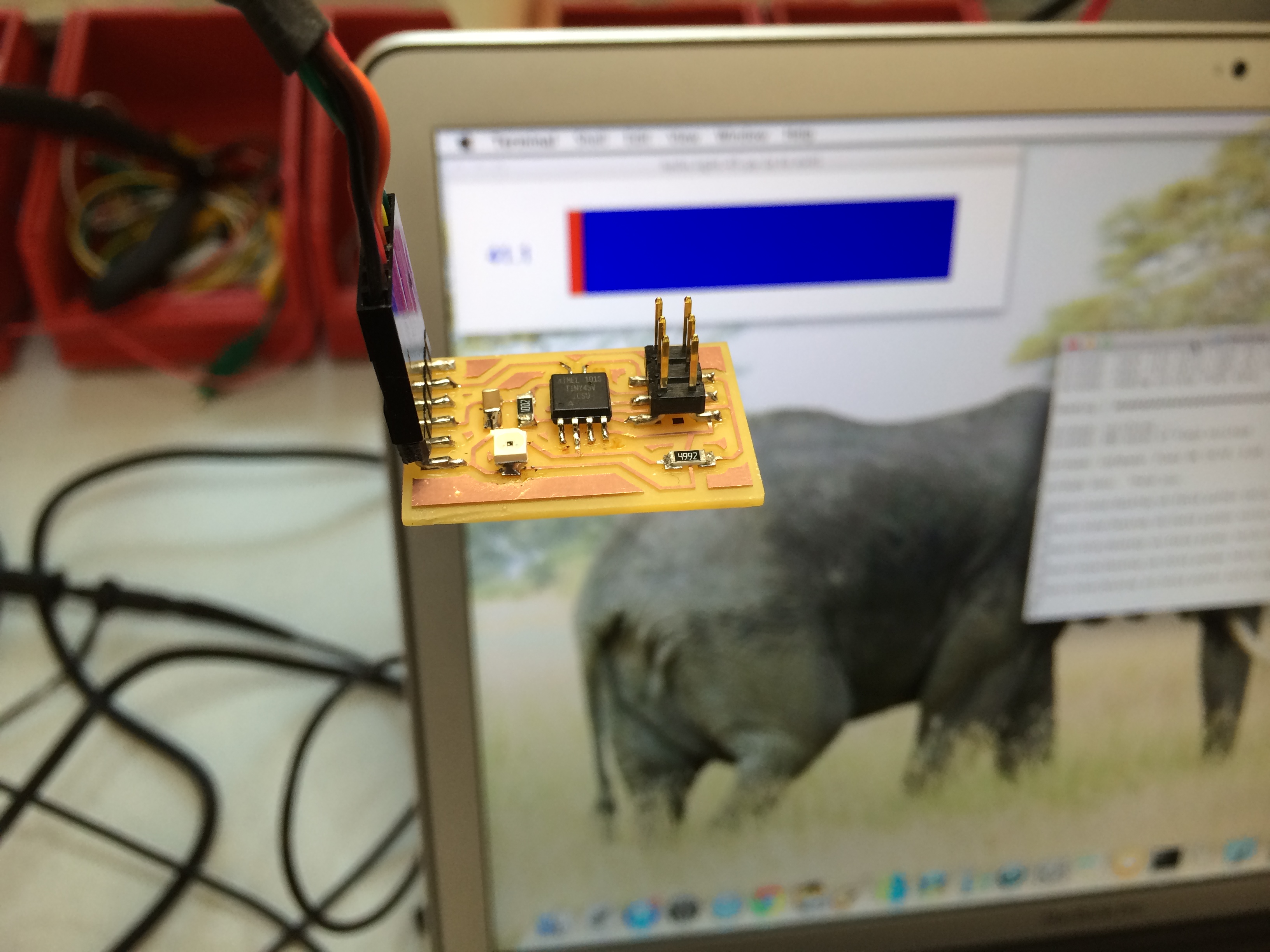
Phototransistor sensing the normal light in the room.
Phototransistor sensing the light while it is covered with my finger.
|
 Fab Academy Class 2014