Soldering Iron with temperature controlled soldering station
For my final project I would like to make a soldering Iron with a temperature controlled soldering station. The idea of making a soldering iron was based on Neil's suggestion in one of the sessions.
In the week14 , and week16 I have completely explained what is the project about, how it works and what are the ports. In this page I will write about the implication of the project.
Soldering Iron
Heating Element
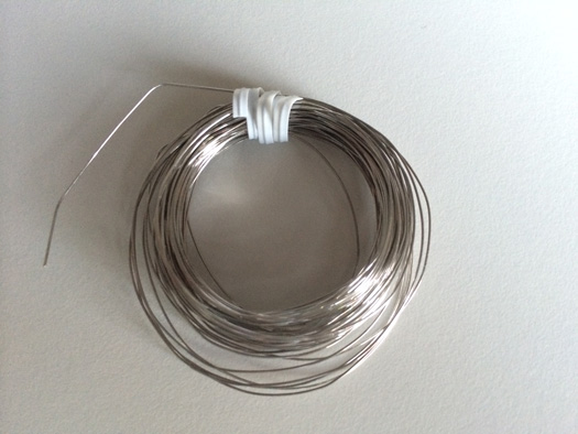
For the soldering first I needed to buy the suitable nichrome wire. Nichrome wires have different gauges. Each gauge is mapped to a diameter. The bigger is the gauge the smaller is the diameter.There are several parameters related together like voltage, length of the wire, temperature and the gauge. I found an online calculator for choosing the right wire. Based on some calculations I decided to use nichrome wire gauge 22. The resistance for 1 meter of this wire is about 6 ohms. I measured the resistance of the wire after buying and it was about 6 ohms for one meter.
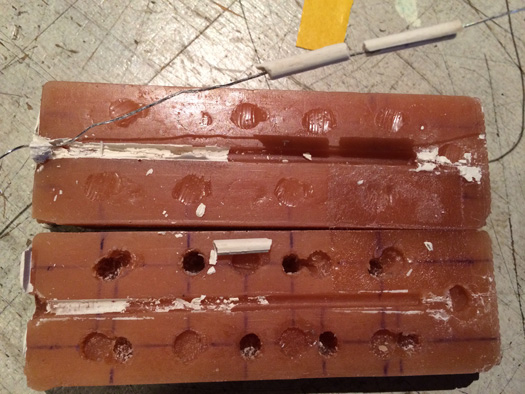
The nichrome wire should be casted in hydrostone to make a heating element. For that I decide to do two processes of molding and casting. The first one a cylinder with the diameter of 3 millimeters. I planned to cast the thermocouple that I explain in a bit and the nichrome wire in this mold. The cylinder had a diameter of 3 and the height of 8 centimeters. One line of nichrome wire would be inside the cast and from one end I started to wind the wire around the hydrostone. So one side of the wire would be inside and the other side would be outside.
The whole thing would be casted in the second mold. The second mold was a cylinder with the diameter of 6 millimeters and height of 10.5 centimeters. It also had a shape for the tip of the Iron. The tip of the iron should be out of metal. Because hydrostone does not get any solder. Therefore one way of doing this part was to cast the whole thing with hydrostone and then later cast some metal on the tip. And the second was to put one the tips from the inventory in the cast already. I decided to do the latter, because in fablab there was not a possibility to cast metal and the goal of this project was to be doable in a fablab.
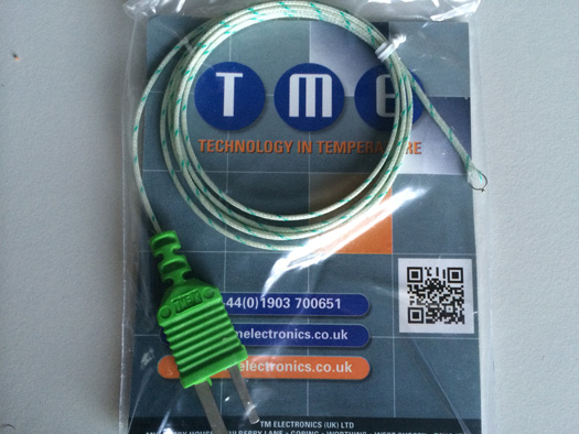
The thermocouple was an important part of the iron too. The temperature sensors which were in the inventory could be working up to 150 degrees centigrade. I found a thermocouple which could work up to 450 degrees centigrade.
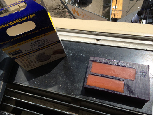
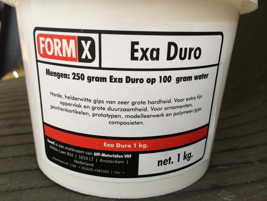
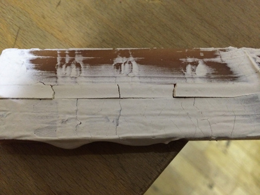
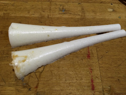
What I got as hydrostone was Exa Duro. I got it from Formx because hydrostone is not available in Europe. I casted with that but it was breaking when I was taking it out of the mold. I practiced more that 10 times, playing with ratios, casted in double sided mold and one sided, put it in the oven and outside the oven, but it did not work. You can see the pictures in the following.
I also tried not to put the wire inside the mold and see what was happening. I found out that it was still breaking.
Note: I should explain making mold process too. Because the machining is taking a lot of time, making the double-sided mold it is possible to make only one side of the mold if the two sides are identical. For double sided mold usually it is good to design some holes in one side and some spikes in the other side for the perfect alignment. In fact in identical sides machining the side with the holes would be enough. Then one mold can be made out of that. Then some external spikes can be placed in the holes and make the second mold. There are two important points here. First the diameter of the holes should be the size of the available spikes. Second the holes should be symmetrical around the model otherwise the top and the bottom won't match. I made this mistake in the model and after molding I realised that they are not matching.
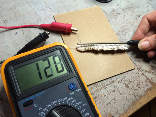
After all these I decided to just pour some of the Exa Duro without a spacial shape and bury the wire inside, then turn the out-coming wire around it. I connected it later to the power supply with 12 volts and fed 2 ampers to it. I used one thermocouple and connected it to the multimeter to check the temperature. Actually temperature was rising very nicely. In the second test we saw that it can even melt the solder.
Soldering Iron handel
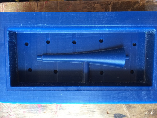
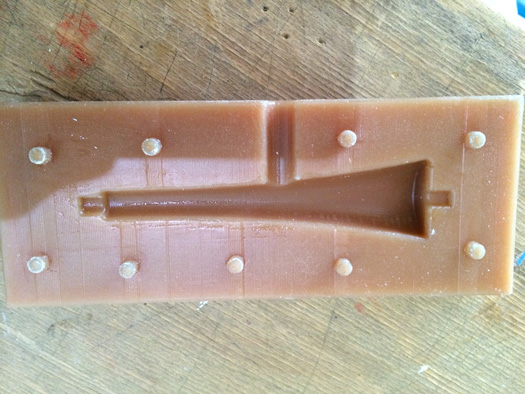
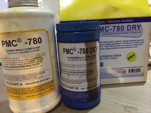
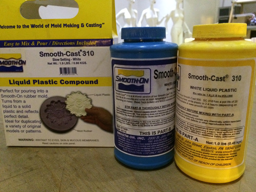
For the handel I designed and made a double sided mold. Inside the mold should be hollow with the diameter of 6 millimeters that the heating element can fit in from one side. Also wires can get out from the other side. For this I used shopbot to machine the wax. Again I did not put the holes symmetrical that caused me some problems. Also I put the place for pouring the cast in the middle which was not indeed a good place. I use a metal bar with diameter of 6 millimeters to insert it inside the mold. I used vytaflex 40 for making the molds and I did casting with two different materials, PMC-780 and smooth-cast 310
I machined the wax with shopbot
I made the mold with vytaflex 40
I made the final casts with PMC-700 and smoothcast 310
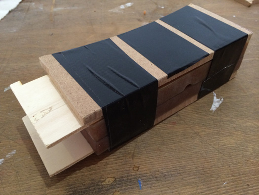
I tried to keep the two sides of the mold tight together with some wood and tape. The metal bar is already inserted between the two molds
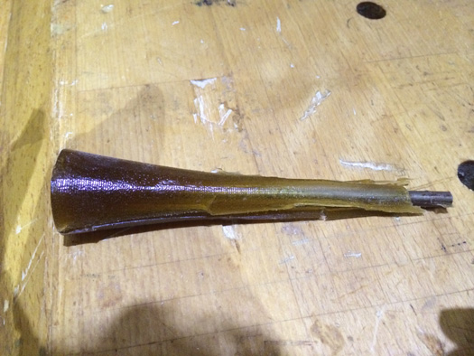
As I mentioned above the place that I chose for pouring the cast was not good. And the results showed that I haven't been able to fill the whole space. I should redesign the model and pour the cast from the top side which is bigger.
I tried to do two separate casts and join them together but the results showed me the lower part that I had designed as 6 mm is not coming out of the mold thick enough.
I did two separate casts with smooth cast 310 to see if this material could be better.
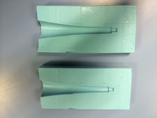
As I mentioned above the place I had decided to pour the cast was not suitable because it was in the middle of the handle and it was not possible to fill the mold from that place. Therefore I made another double sided mold that I can cast from the top, the larger part.
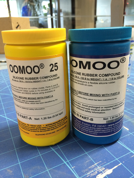
For making the molds I used oomoo 25 that I had used before on week 9.
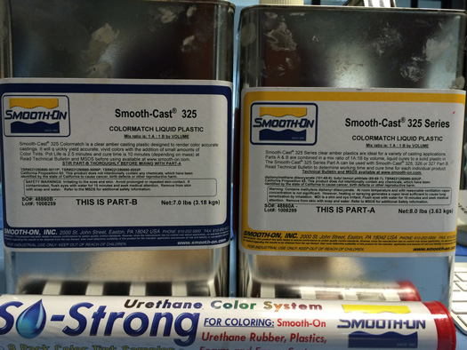
Material from smooth-on to make the molds.
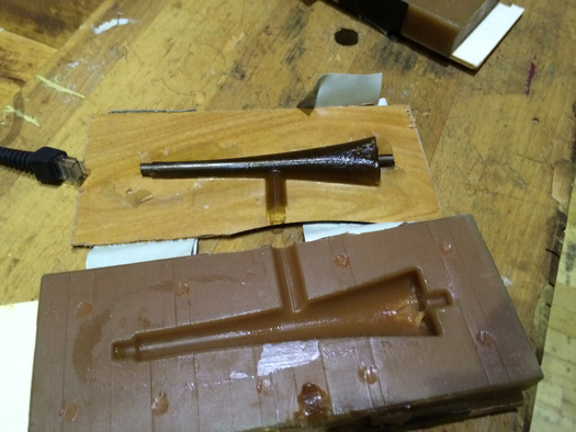
Two parts of the double sided mold.
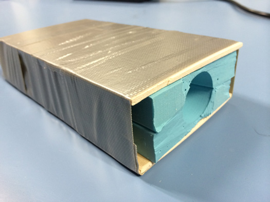
I put the two parts of the mold together each of them backed with a peice a plywood. Then I kept them together with tape.
Double sided mold.
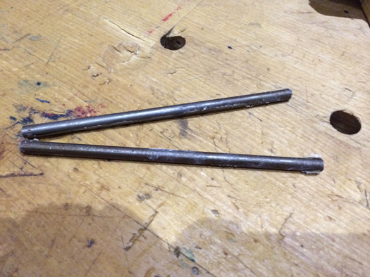
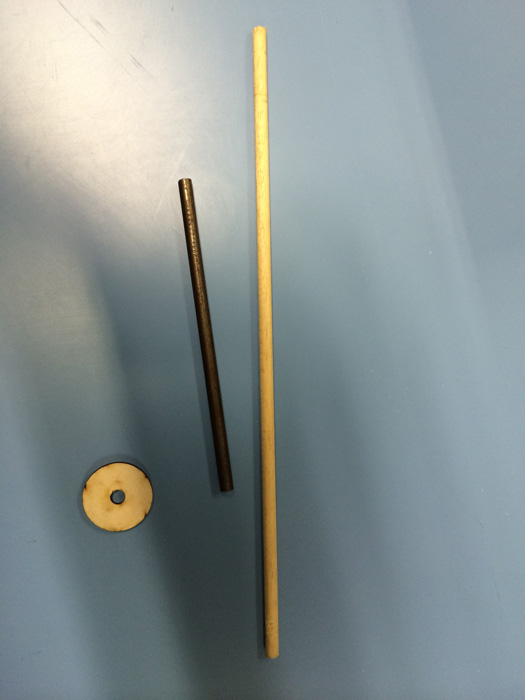
I wanted to use the same idea for insertion molding and put a metal bar with the diameter of 6 mm inside the mold after casting. To keep the bar exactly in the center I cut a disk with outer diameter of 3cm and inner diameter of 6mm to fit on the top of the mold and can keep the bar nicely.
Disk and bar.
In the picture above you can see a metal bar and a wooden bar with 6mm diameter. I used the metal bar.
Smooth-cast 325
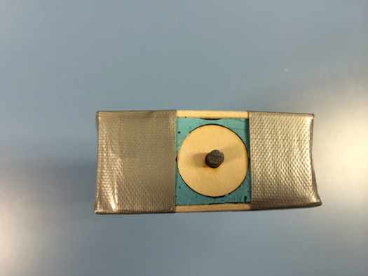
Then I casted in the mold using smooth-cast 325 and inserted the metal bar inside. Also I placed the disc on the upper part of the mold. It is important to spray the mold and the metal bar with mold release agent before casting.
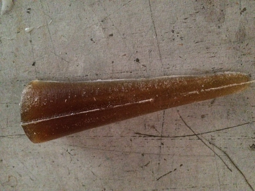
After casting
The following picture shoes what it came out of the casting.
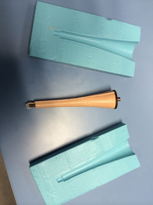
The soldering iron handle
After getting the handel out of the mold I should have taken the bar out which was easy to do and the handle was ready.
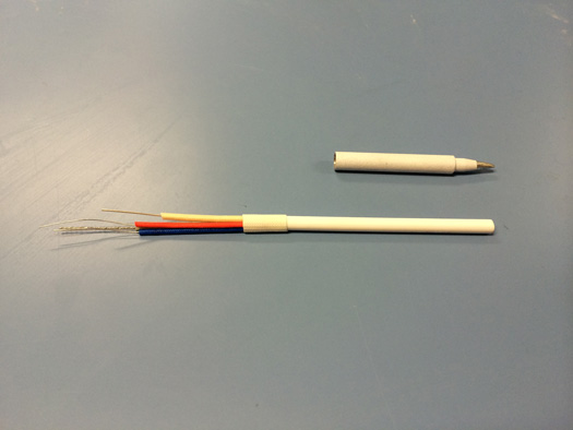
I bought the heating element and the tip for soldeting iron from farnell. As you may see in the picture, there are four wires coming out of the heating element. Two of them are for the resestive element and the other two are for the thermocouple (red and blue).
Heating element and soldering tip
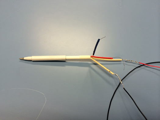
When I attached the soldering tip to the heating element it was a bit loose. I used two small wires to fix it in its place. Then I extended the wires of the heating element. The diameter of the inner hole that I had desined for the handle was 6mm. Also the the diameter of the heating element was 6 mm too. So they fit together nicely and the soldering iron was ready to be tested.
Extending the wires of heating element
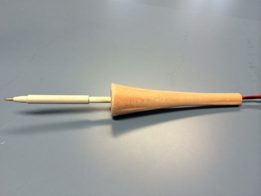
The following picture shows puting the heating element into the handle
Soldering Iron
The soldering station
Arduino shield
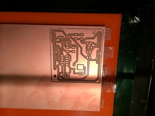
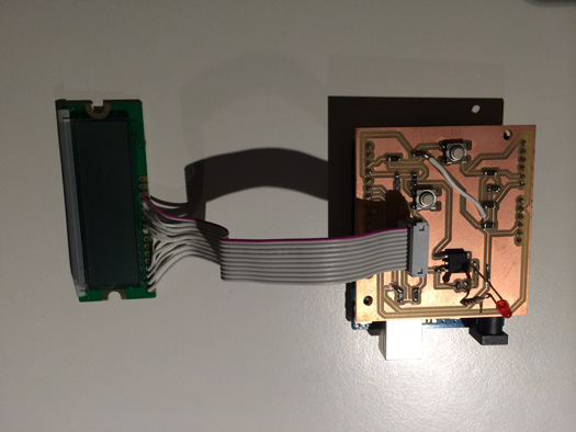
In the soldering station part, first I designed an Arduino shield having an LCD, temperature sensor, two buttons and the power mosfet. The design and testing went very well and tested the functionality of all the parts and all were working fine.
One of the traces was disconnected so I connected it with a wire.
Control board with Atmega 328p
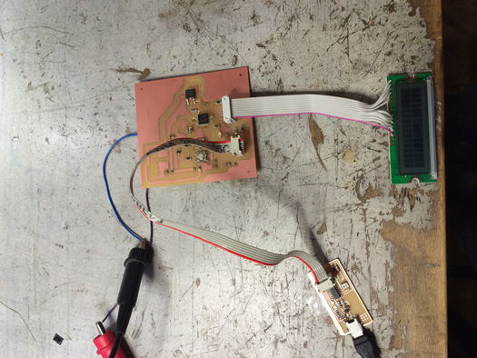
After checking the functionality I designed and fabricated the control board using Atmega 328p. The main difference was reading the data from the thermocouple instead of a temperature sensor. I used one IC MAX6675 from Maxim to convert the data from thermocouple to the microcontroller.
Because I wanted to use the Arduino IDE to program later, I had to be aware that how the pins on Atmega 328p and Arduino are mapped together. Here is how they map together. I also add one column to which I connected the peripherals.
Pin on Atmega328p
Arduino
My connections
1
D3
Gate of Power Mosfet
2
D4
-
3
GND
GND
4
VCC
VCC
5
GND
GND
6
VCC
VCC
7
-
XTAL1
8
-
XTAL2
9
D5
RS on LCD
10
D6
-
11
D7
-
12
D8
downButton
13
D9
upButton
14
D10
~CS
15
D11
MOSI
16
D12
MISO-SO
17
D13
SCK
18
VCC
VCC
19
A6
-
20
AREF
VCC
21
GND
GND
22
A7
-
23
A0
DB4 on LCD
24
A1
DB5 on LCD
25
A2
DB6 on LCD
26
A3
DB7 on LCD
27
A4
-
28
A5
-
29
RESET
RESET
30
D0
-
31
D1
-
32
D2
E on LCD
In the schematics I connected RS of the LCD to pin number 19 and E on LCD to pin number 22 which were not right. Then in the debugging I cut the traces and connected RS to pin number 9 and E to pin nimber 32 with two very thin wires.
Programming and the Code
I used the Arduino IDE to write the code. I did not put any FTDI connector in my board. I just put an AVRISP that it can be possible to program it using a FABISP.
Because I was using the 20Mhz resonator, for being able to use Arduino IDE I had to make a hardware folder in Arduino directory and put a file with the name of board.txt in it. Zearc from Amsterdam helped me to modify a former text file and get the correct fuses. In the txt file the following information should be written.
//This is the name that comes in Tools >> Boards section of the Arduino IDE
FinalProject.name=Soldering station board boot loader
// I did not change this because it was not relevant
FinalProject.upload.protocol=stk500
// I did not change this because it was not relevant
FinalProject.upload.maximum_size=14336
// I did not change this because it was not relevant
FinalProject.upload.speed=19200
/* These are the low_fuse, related to resonator and the chip that
should have the correct value on the chip.
It was not important here because I was not burning the boatloader. */
FinalProject.bootloader.low_fuses=0xf7
// These are the high_fuses that should have the correct value on the chip.
FinalProject.bootloader.high_fuses=0xda
// These are the extended fuses that should have the correct value on the chip.
Now everything is ready for uploading the code. For uploading the code I should first select the right board. The one that we gave a name to it in our board.txt file. Under the Tools in programmer section USPtinyISP should be selected. Then instead of using Upload button, file >> Upload using programmer should be used.
Transformer
I was planning to use an external adapter to down-convert the voltage but later I decided to get a transformer and try it. Although I did not try the transformer but I put the rectifier circuit on the control board.
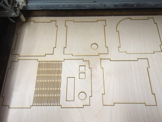
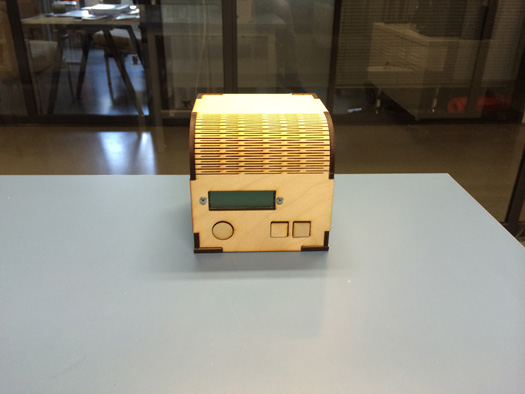
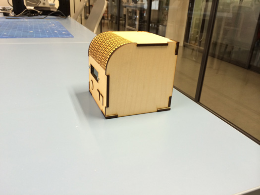
Housing
I used the laser cutter to make a housing for the station.
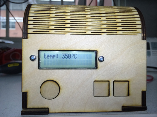
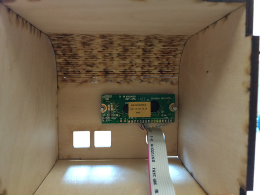
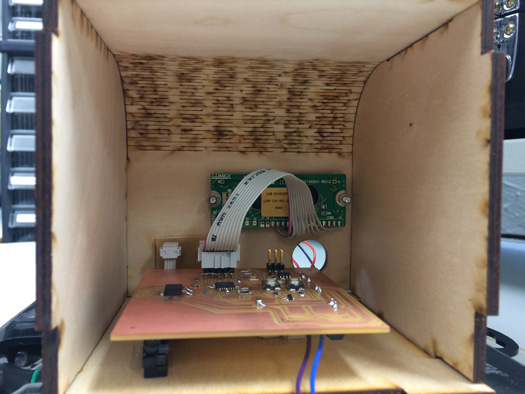
Basically what is inside the housing is the electronics circuit that I made above. First I fixed the LCD in its place as you may see in the following picture.
LCD inside the Housing
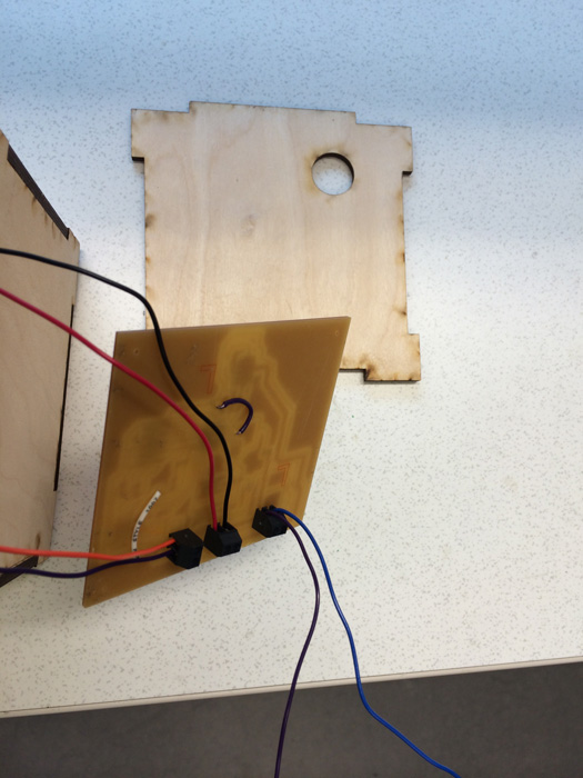
Then at the back of my board I had connectors for connecting to the power supply, connecting the Mosfet to the iron and also connecting the thermocouple to the IC MAX6675. You may see all the connections in the following picture.
Connections
There was a thought to use a transformer, therefore I made the housing this size that my transformer can fit. Finally I used an external adapter that could give me 24 volts and 2 ampers. So I had plenty of space to fix the circuit inside the housing.
As you could see in this design when I put the circuit inside accessing the switches is not trivial. For that there are two choices. First, making a smaller board, containing the switches and connect it to the main board. The other choice is to change the housing/board design that the switches can be accessible.
I decided to make one separate board for the switches and connect it to the main board. I also redesigned the control board to have the connectors for the switches and also fixed the two LCD-Microcontroller connections that were not right.
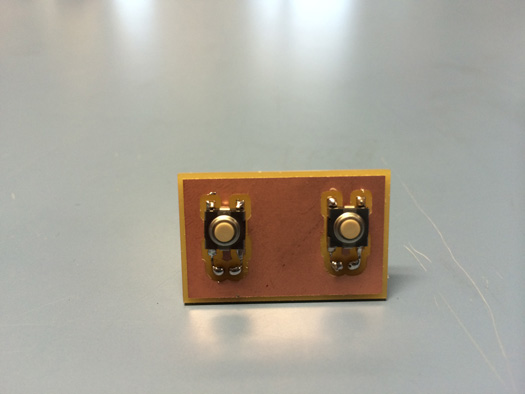
Switch Board
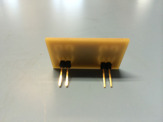
Back of Switch Board
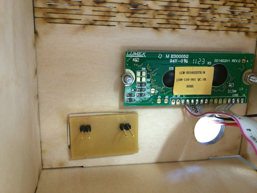
When I wanted to put the switch board in place I saw the buttons would be out of their places very much. So I levelled the board by gluing two strips of 3 mm plywood to the top and bottom part. Then used one drop of glue to attach the wooden button to the switch. It worked pretty well. This part should be done with care otherwise the botton will be glued together.
Switch Board in the housing
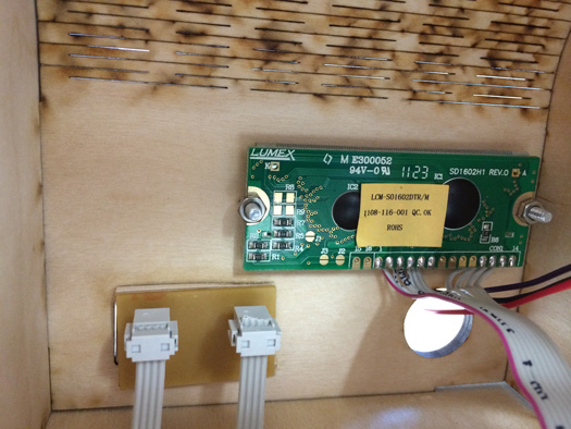
Switch Board with the connectors
Inside the housing
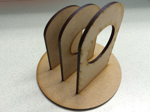
Soldering iron stand
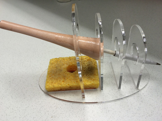
When we were talking to Alex, he told me it is nice to make a stand for the soldering Iron too. I made the first prototype with MDF using the laser cutter and after that make it with clear acrylic. In the second version I also put some space for the sponge.
Soldering iron stand
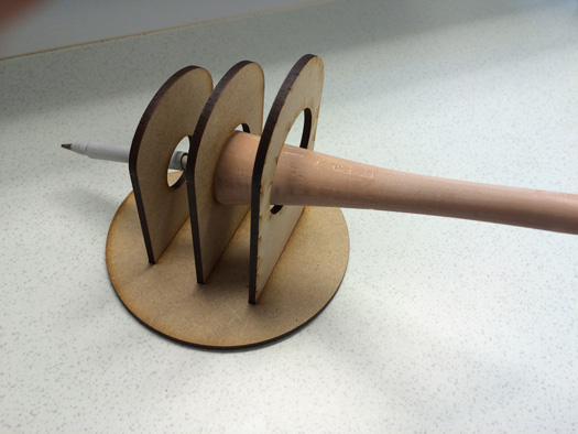
Soldering iron stand holding the iron
Soldering iron stand with sponge
Soldering Iron in action
Soldering one component on the board with the made soldering Iron
For the next version I would like to make the housing with CNC milling, consider a place for the circuit and fit it there.
 Fab Academy Class 2014