|
Week 4: Making a FabISP
This week assignment was to make a fabISP, which is an in-system programmer. For this task the layout and BOM (built of materials) were already provided.
The assignment had 3 parts. First to mill the board (making the PCB), second to solder the components on top of that and third to program it.
Milling the board (making the PCB)
For milling the board I was using Roland Modela MDX-20. There were two milling bit sizes required, 1/64 for the traces and 1/32 for cutting the board out. The PCB material used was FR1. The FR1 PCB should be fixed on the Modela bed with double sided tape.
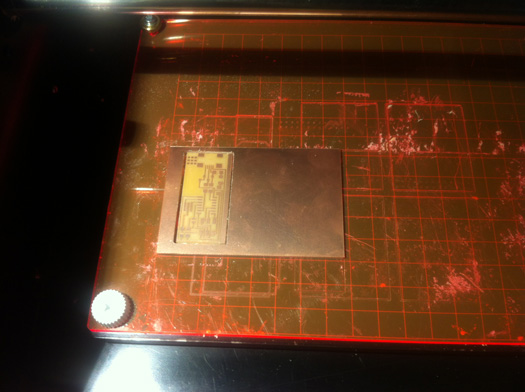
PCB after milling on the Modela
The process
First I needed to download the layout (traces) and the interior (for cutting the board that you can get it out of the bigger cupper clad.)
After that I fired up the terminal in Ubunto and started the fab module with the fab command. Then there would dialogue boxes that are very intuitive.
In the first dialog box it should be selected from what format to which format. For making the PCB with modela they are:
From format: image (.png)
To format: Roland modela (.rml)
And after that the “make_png_rml” button should be pressed
There is going to be another dialogue box in which I did the following settings. For the traces:
Selecting the bit size: (1/64)
Loading the .PNG: loaded the traces.png, which I had downloaded from Neil’s keynote
Checking the size: here it should be checked that the size of the board is correct.
Diameter (mm): 0.4
Offset (-1 to fill): the default value for the offset is 4. I milled one board using this value and then in the second round I changed it -1 to mill all of the unwanted copper.
Overlap: 0.5
2D threshold: 0.5
Error pixels:1.1
2Dz (mm): -0.1 this is how deep the mill goes to make the traces.
make .path: pressing the make path button, the cutting path would be visible.
Changing the offset the path will change.
After this step the speed should be selected. The default Value is 4 but because I was using the new drill bit I used the speed of 2. Jog can be set to 1.0.
Xmin and Ymin are related to where you have put your board in the Modela plate. When Xmin and Ymin are set, pressing the Move to X and Y, the milling bit will go to that coordinate.
These value should be remembered.
After the modela was turned on and the bit was put to it place, the view button on the modela should be pressed. Pressing the view button the drill bit will go in the left lower corner and would be ready for start.
Note: if in the middle of the process something was not working properly with the view button the process could be stopped.
For setting the Z, the milling bit should touch the board. First using the down button on the modela to bring the milling bit as close to the board as possible. The down button should be pressed for more than one second that the bit starts going down.
When the bit was very close to the surface the bit holding screw should be loosen that the bit drops down a bit and touches the surfaces. Then the screw should be tightened.
At this point everything is set. The button “Make rml” should be pressed and a bit Send button will appear. Pressing this button the job will start.
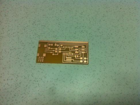
FabISP PCB
As you can see in the picture you can attach as many of them as you want together and create some shapes.
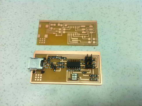
FabISP PCB before and after soldering the components
Cutting the board out
First the milling bit should be changed to (1/32)
Then in the fab modules the interior .png file should be loaded and the (1/32) milling bit should be selected.
The settings I used were as follows.
Diameter: 0.79
Offset: 1.0
Overlap: 0.5
2D threshold: 0.5
Error: 1.1
2Dz(mm): This is related to the thickness of the board, which was 1.55 mm. I added 0.2 mm and set this value to -1.57
Speed: I used 0.5 mm/s
Jog: 1.0
Xmin, Ymin : They should be the same as for cutting the traces that the machine starts from the same origin.
After the job is done. View should be pressed, the board should be taken out, the fixing tape should be taken out and dust should be vacuumed.
Soldeing
For the soldering I can use some of the tips I used.
Putting your arm on the table is very important otherwise your hand will shake and you don’t have a good control.
For the traces and the components that are very tiny it is better to use a microscope. I did not use it for this exercise.
When the traces are very close together it is good to use some flux first, put the component on the board and then solder. Using flux will help the tin to find its place and avoid the adjacent pin to attach together to some extent.
Programming the Microcontroller
For programming the board there is a need for a set of software and a programming board.
I had an AVRISP MK2, but I did not have the drivers for that. I also did not know that it was working or not. AVRISP MK2 has to LED indicators. The first one, which is inside near the USB connector turns green if the computer detects the programmer itself. For me it was not the case.
I was using Mac. I downloaded crossPack and did all the required settings but it did not work. Downloading the LibUsb did not help either. Then I tried windows. I downloaded the Atmel Studio 6.1 but the AVRISP MK2 could not be recognized. I changed the usb drivers to the ones from libUseb and it was detected. I got the inside green light.
In the next stop I connected the target board and did all the settings to start programming but it failed. I read later on some forums the usb drivers I was using were not compatible with Atmel studio.
After that I download Ubunto followed by installing avrdude and GCC. AVRISP MK2 was detected. I connected the target board, that was also detected. I had boath leds green. I did all the settings based on the tutorial and everything went fine. Finally I managed to program.
I also tried to use an Arduino as an ISP programmer. There was a tutorial how to do it on the Arduino website, but it was all based on Arduino IDE which is not reading .c or .hex files.
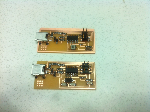
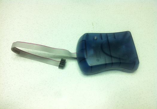
FabISP with resonator and FabISP with Crystal.
This is the AVRISPMK2 that I used for programming.
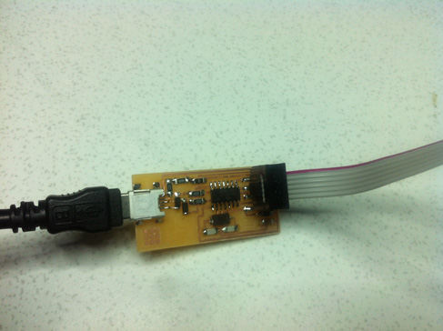
In this picture it the connection of the ISP cable is shown.
Checking that FabISP is detected
After programming I connected the FabISP both the Mac and Linux. FabISP was detected successfully
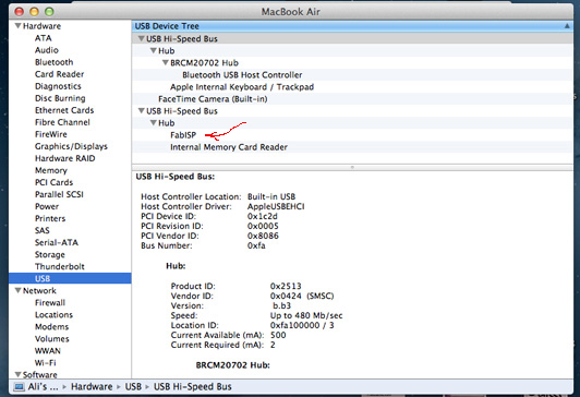
FabISP is detected on Mac.
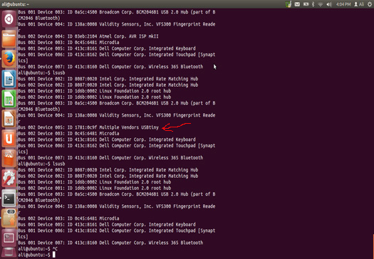
FabISP is detected on Linux.
|
 Fab Academy Class 2014