This week assignment was to design a board for an output device and experiment with it. Although all of the output devices in Neil's keynote were interesting to experiment with, I decided to make a board for an LCD because in my final project I am using an LCD.
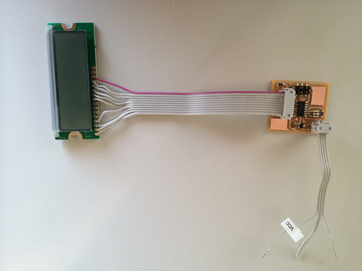
I started to design the board in Eaglecad. For connecting the LCD to the board I was planning to use the flat cable and a IDC 2x5 connector. Therefore on the board I needed a 2x5 pin header that I did not find in eagle libraries. Because of that I decided to modify the AVRISP that had a footprint of 2x3-smd. I found a tutorial on Youtube how to modify a part of library in Eaglecad . I also found two more tutorials from sparkfun and instructable for making library parts in Eaglecad which were useful.
For making the part, the first problem I encountered was that I could not save the parts in the libraries. I searched for what it could be the reason and found out that I did not have the permission to write in my Eagle folder. I went to my eagle folder and gave the permission of read and write to it. The second problem was when I had made the part ready but I was getting an inconsistency error between sch and brd. I could place the part in schematics but when I was going the board view I could not see that. I did not understood why it was happening. Finally I did all the same in another computer and it worked.
Designing the board
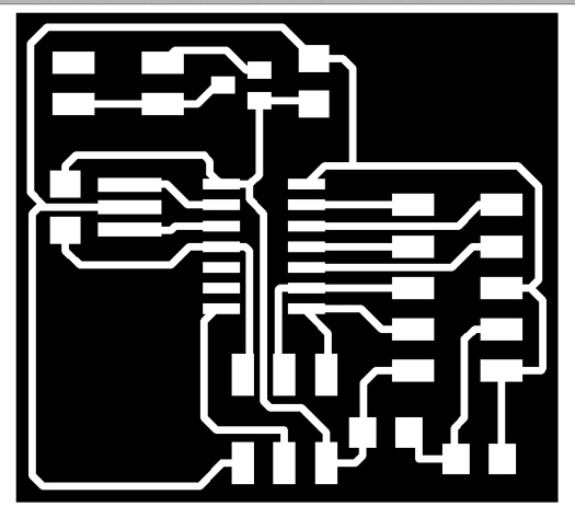
I designed the board the same way as former weeks in Eagle cad. Then I exported it as a .png file from Egalecad with the resolution of 500 dpi while monochrome was checked. I opened this file in GIMP, cropped it in the size I wanted and made two files for traces and the interior.
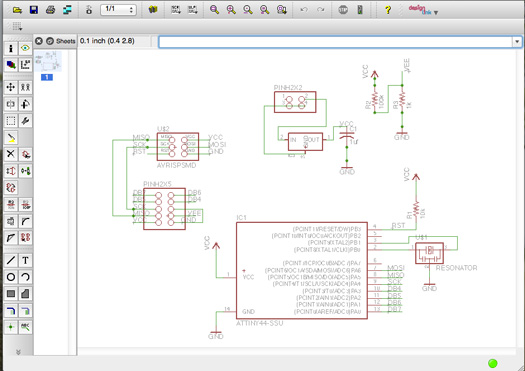
The schematics
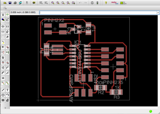
The layout
The traces
The interior
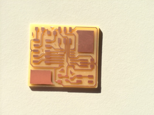
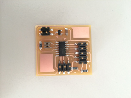
Making the board
I made the board like former sessions and then soldered the componets.
When I started to burn the bootloader with the Arduino IDE I got an error. I started to check if the Attiny 44 is getting the power, becuase the power is the first important thing that should be checked. I realised that the 5 volts trace which is coming from the regulator is reaching the Attiny, but when I was trying to check the voltage on pin 1 (Vcc) and pin 14 (GND) in Attiny 44 I did not getting the 5 volts. I checked all the traces again and realised that the ground traces on the board are not connected to the one from the power supply. I connected them with a bit of solder and the problem was solved.
After burning the bootloader I tried to upload my code. Before uploading the code I had to relate the Arduino pinout with Attiny pinout. After spending a bit of time reading the data sheets I understood the following relation would work. R/W pin in LCD is grounded.
LCD
Arduino
Attiny 44
Rs
12
5
E
11
4
D4
5
3
D5
4
2
D6
3
1
D7
2
0
Then considering the mapping above instead of the command LiquidCrystal lcd (12, 11, 5, 4, 3, 2); which is meant for Arduino the command LiquidCrystal lcd (5, 4, 3, 2, 1, 0); should be used for Attiny44.
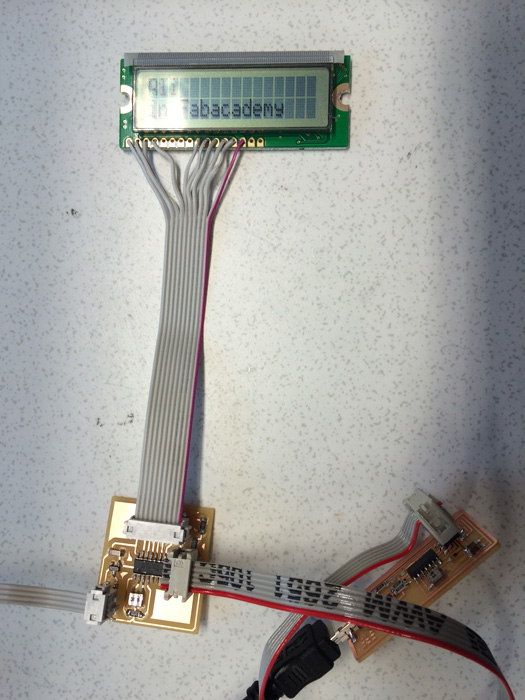
LCD showing the data
I tried several sketches from the arduino examples, modified them and played with them to learn about them. Then I would like to use the serial communication, for example I type something in my keyboard and LCD shows it. But when I had some commands regarding serial communication like Serial.begin(9600); in my code, I would get an error uploading the code.
I found out what was wrong with Serial communication. The Attiny 44 does not have a UART, but Arduino does have a UART. Attiny 44 can have a serial communication based on software. The SoftwareSerial which should be included in the begining of the code as #include library can be used in this regard.
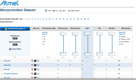
Atmel microcontroller selection page
Sample code
One sample code that I tried was for making custom characters. I learned how to do it when I was watching Jeremy Blum video about LCD. As mentioned above the LCD I was using was 16x2. In each of these spots there are 5x8 pixels that can be turned on or off to make new custom characters.
 // include the library code:
#include

// initialize the library with the numbers of the interface pins
LiquidCrystal lcd(5, 4, 3, 2, 1, 0);

byte firstColume[8] ={

    B00000,
    B00000,
    B10000,
    B10000,
    B10000,
    B10000,
    B00000,
    B00000,
};

byte secondColume[8]={

    B00000,
    B00000,
    B11000,
    B11000,
    B11000,
    B11000,
    B00000,
    B00000,
};
byte thirdColume[8]={
    B00000,
    B00000,
    B11100,
    B11100,
    B11100,
    B11100,
    B00000,
    B00000,
};
byte fourthColume[8]={
    B00000,
    B00000,
    B11110,
    B11110,
    B11110,
    B11110,
    B00000,
    B00000,
};
byte fifthColume[8]={
    B00000,
    B00000,
    B11111,
    B11111,
    B11111,
    B11111,
    B00000,
    B00000,
};


void setup() {
  // set up the LCD's number of columns and rows:
  lcd.begin(16, 2);
  // Print a message to the LCD.
  lcd.print("Fabacademy 2014");

  lcd.createChar(0, firstColume);
  lcd.createChar(1, secondColume);
  lcd.createChar(2, thirdColume);
  lcd.createChar(3, fourthColume);
  lcd.createChar(4, fifthColume);

}


void loop() {
  // Moving the cursor to second line
  lcd.setCursor(0,1);
  //clear the second line when it reaches to the end
  lcd.print("                "); //16 spaces
  for (int i = 0; i < 16; i++)
  {
      for (int j=0; j < 5; j++)
      {
        lcd.setCursor(i,1);
        lcd.write (j);
        delay(80);

      }

  }

}
 Fab Academy Class 2014