13. output devices
output
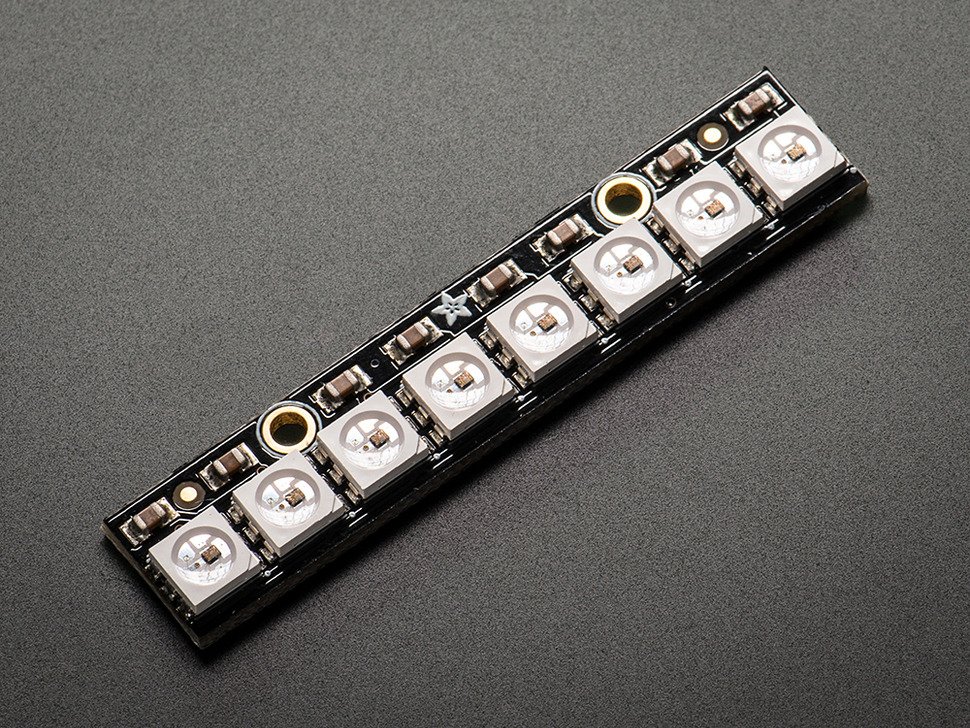
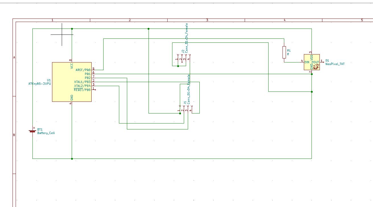
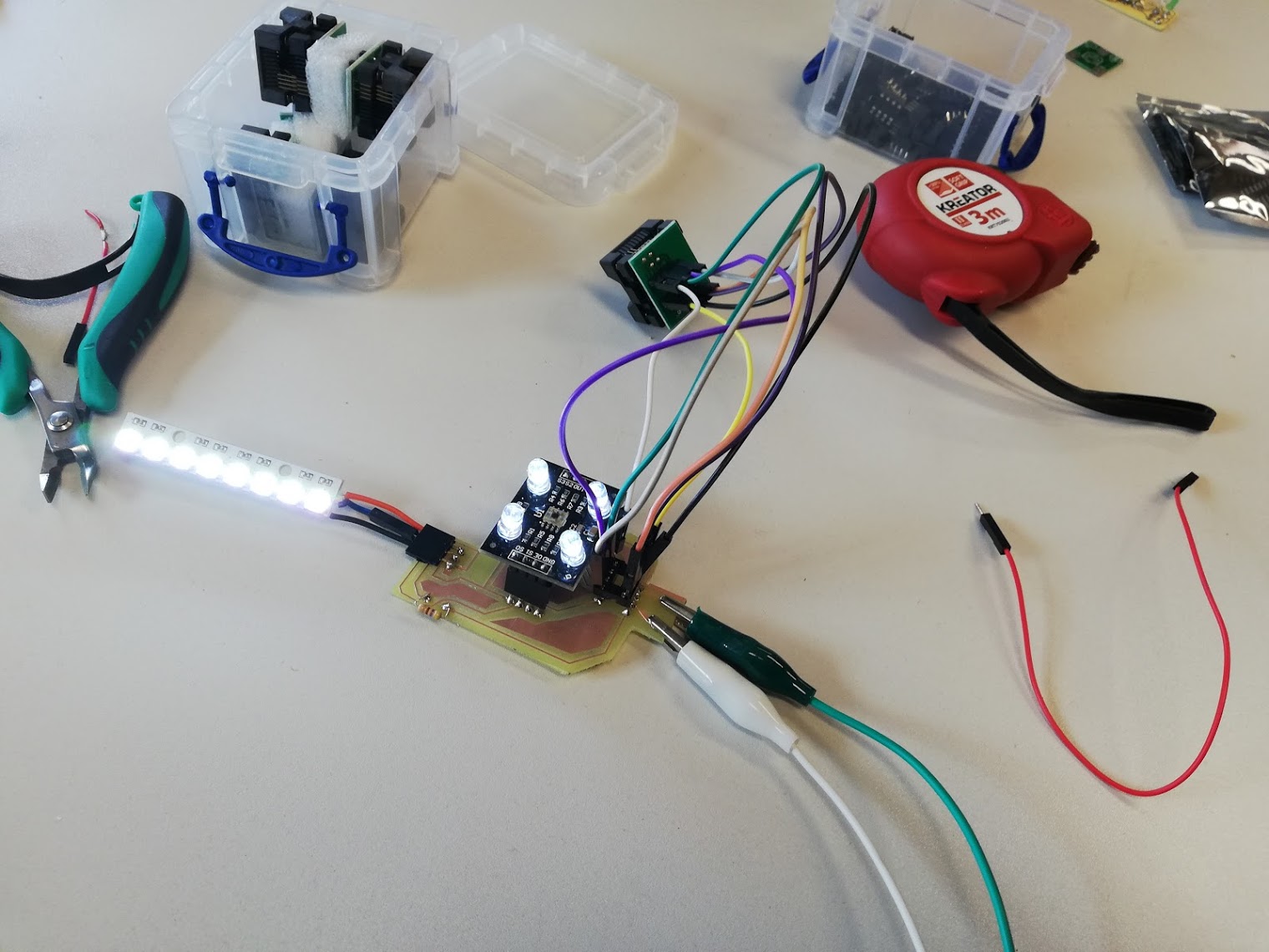
As output device i added a neopixel to the board. from the input week. The neopixel should mimic the color that is shown before the sensor. I changed the board of last week and i added a neopixel that mimics the coulour in front of the sensor. I worked on this assigment at the same time as the input week. So they work back to back.
datasheet
general Description :
WS2812 is a intelligent control LED light source that the control circuit and RGB chip are integrated in a package of 5050 components. It internal include intelligent digital port data latch and signal reshaping amplif ication drive circuit. Also include a precision internal oscillator and a 12V voltage programmable constant curre -nt control part, effectively ensuring the pixel point light color height consistent. The data transfer protocol use single NZR communication mode. After the pixel power-on reset, the DIN port receive data from controller, the first pixel collect initial 24bit data then sent to the internal data latch, the other data which reshaping by the internal signal reshaping amplification circuit sent to the next cascade pixel through the DO port. After transmission for each pixel,the signal to reduce 24bit. pixel adopt auto resha -ping transmit technology, making the pixel cascade number is not limited the signal transmission, only depend on the speed of signal transmission. LED with low driving voltage, environmental protection and energy saving, high brightness, scattering angl e is large, good consistency, low power, long life and other advantages. The control chip integrated in LED above becoming more simple circuit, small volume, convenient installation.
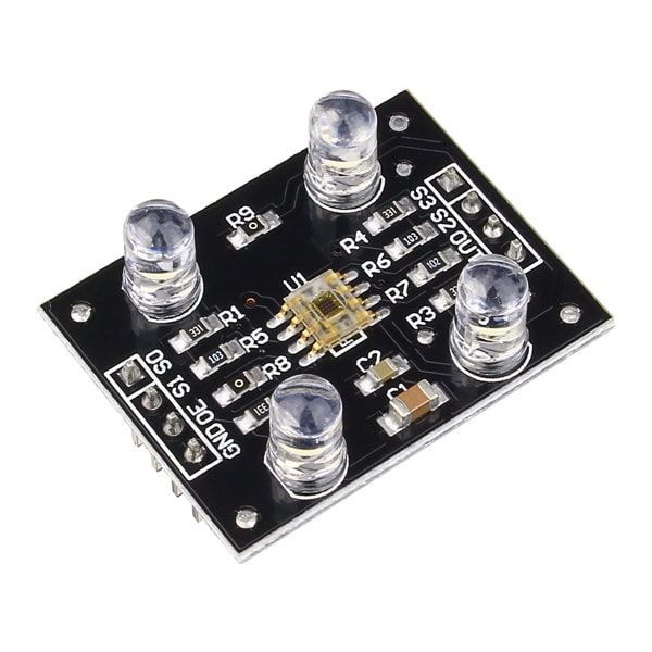
pins
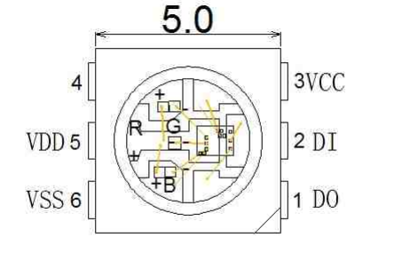
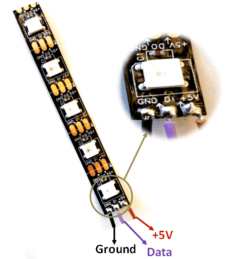
- DO : control data signal output
- DI : control data signal input
- VCC : power supply
- VDD : power supply LED
- VSS : ground
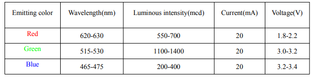
LED parameters
Before making the board I started with making the circuit on a breadboard. When it was working I started in KiCAD. I still find it a difficult proces to make my own boards. I lose a lot of time designing them, the milling part works very well and i understand that complettely but designing them and knowing which components i have to use is still a difficult task that takes a lot of time. That being said I desiged it and milled in with the machine. I used KiCAD for the design and drawing.
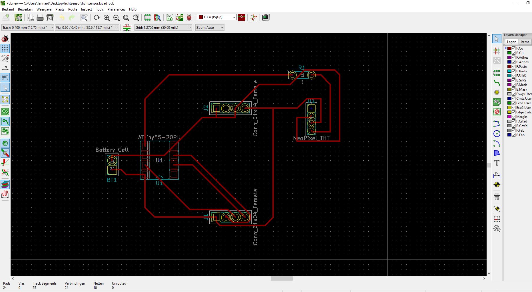
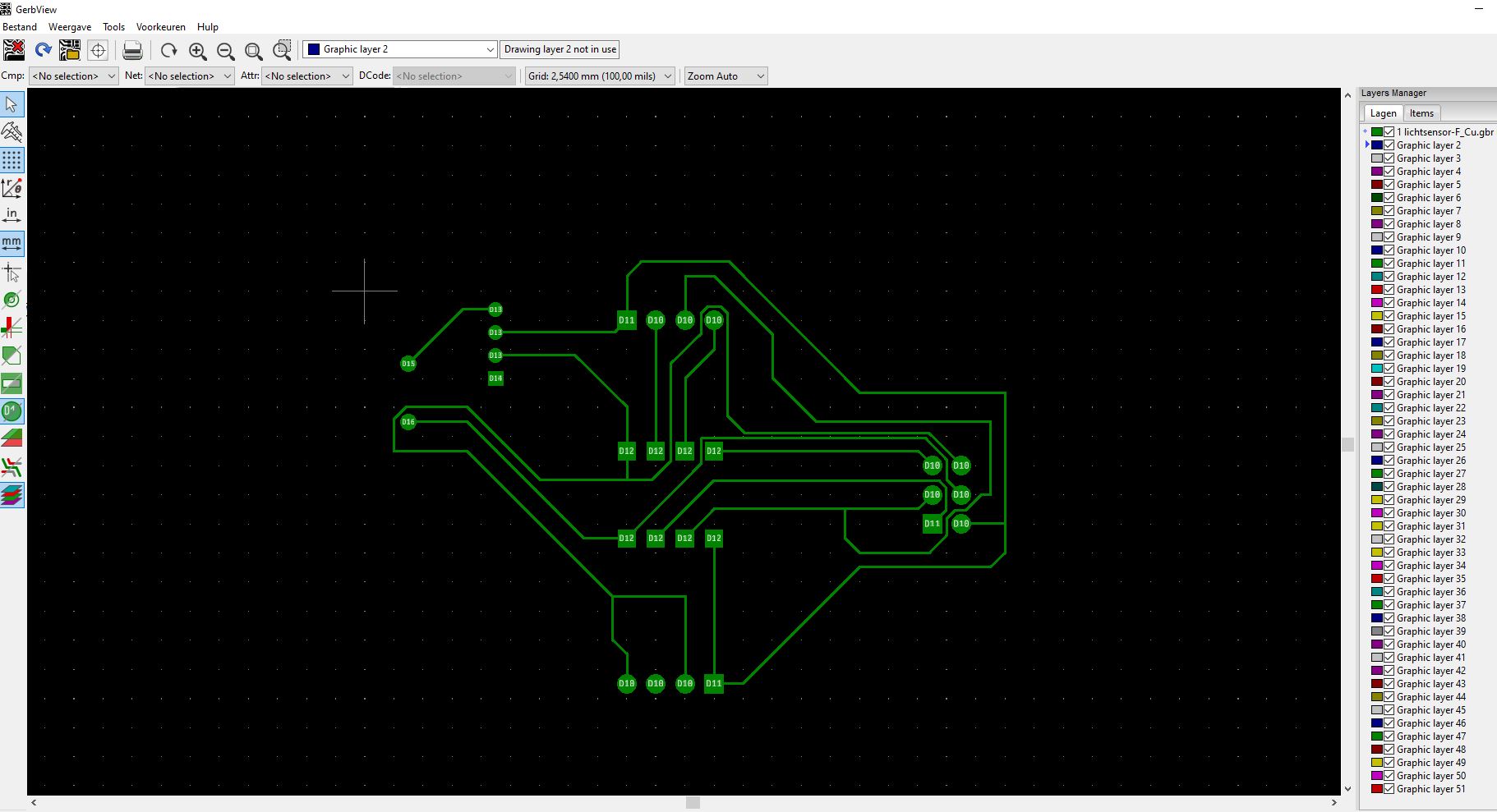
milling the board.
I used the same setting as in week5
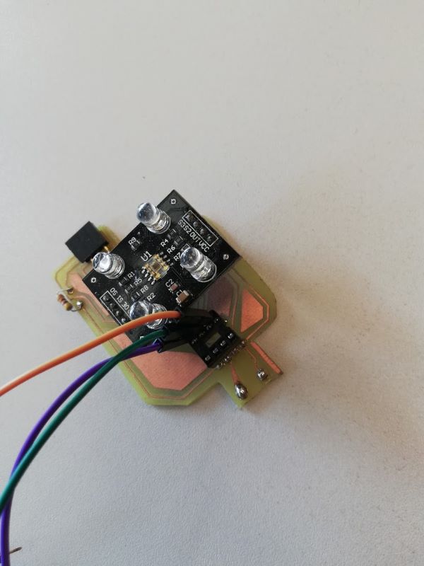
I used this code for this assigment, the neopixel gets data from a colour sensor from the input week. I soldered the neopixel on the board. And with the code below it mimics the colour of the object shown before the colour sensor.
``` define attiny85 false
// set the pin values - Module pins wiring short s0 = 4; short s1 = 5; short s2 = 6; short s3 = 7; short out = 8; short NeoPixel = 10; short s2_attiny = 2; short s3_attiny = 3; short out_attiny = 4; short NeoPixel_attiny = 0;
int Red=0, Blue=0, Green=0, BW_val=0;
int i;
include
void setup()
{
if (attiny85) {
s2 = s2_attiny;
s3 = s3_attiny;
out = out_attiny;
NeoPixel = NeoPixel_attiny;
}
myNeo_NeoPixel = Adafruit_NeoPixel(8, NeoPixel, NEO_GRB + NEO_KHZ800);
if (!attiny85) {
// these are hard wired on attiny85
pinMode(s0,OUTPUT);
pinMode(s1,OUTPUT);
}
pinMode(s2,OUTPUT);
pinMode(s3,OUTPUT);
pinMode(out,INPUT);
if (!attiny85) { Serial.begin(9600); //intialize the serial monitor baud rate // output freq digitalWrite(s0,HIGH); //Putting S0/S1 on HIGH/HIGH levels means the output frequency scalling is at 100% (recommended) digitalWrite(s1,LOW); //LOW/LOW is off HIGH/LOW is 20% and LOW/HIGH is 2% }
myNeo_NeoPixel.begin(); myNeo_NeoPixel.show(); }
void loop() { GetColors(); //Execute the GetColors function
if (!attiny85) { Serial.print(“measuring colour RGB (“); Serial.print(Red); Serial.print(“, “); Serial.print(Green); Serial.print(“, “); Serial.print(Blue); Serial.print(“) - “); Serial.println(BW_val); }
//remap BW_val to 0 to 100, with 0 dark, 100 full light BW_val = map(BW_val,9,110,100,0); //constrain BW_val value to brightness in %; BW_val = (BW_val < 0 ? 0 : ( BW_val > 100 ? 100 : BW_val));
//remap RGB to BW_val 100 values Red = (float) Red /BW_val * 100.0; Green = (float) Green /BW_val * 100.0; Blue = (float) Blue /BW_val * 100.0;
if (!attiny85) { Serial.print(“Remapped brightness colour RGB (“); Serial.print(Red); Serial.print(“, “); Serial.print(Green); Serial.print(“, “); Serial.print(Blue); Serial.print(“) - “); Serial.println(BW_val); }
//remap to RGB values Red = map(Red,15,55,255,0); Green = map(Green,30,105,255,0); Blue = map(Blue,13,45,255,0);
//constrain RGB values; Red = (Red < 0 ? 0 : ( Red > 255 ? 255 : Red)); Green = (Green < 0 ? 0 : ( Green > 255 ? 255 : Green)); Blue = (Blue < 0 ? 0 : ( Blue > 255 ? 255 : Blue));
if (!attiny85) { Serial.print(“Computed RGB out (“); Serial.print(Red); Serial.print(“, “); Serial.print(Green); Serial.print(“, “); Serial.print(Blue); Serial.print(“) - “); Serial.println(BW_val); }
//show on neopixels, dim if dark and not clear to see! if (BW_val > 40) { for (i = 1; i <= 8; i++) { myNeo_NeoPixel.setPixelColor(i-1, myNeo_NeoPixel.Color(Red,Green,Blue)); myNeo_NeoPixel.show(); } } else { for (i = 1; i <= 8; i++) { myNeo_NeoPixel.setPixelColor(i-1, myNeo_NeoPixel.Color(RedBW_val/100,GreenBW_val/100,Blue*BW_val/100)); myNeo_NeoPixel.show(); } }
delay(1000); }
void GetColors()
{
digitalWrite(s2, LOW); //S2/S3 levels define which set of photodiodes we are using LOW/LOW is for RED LOW/HIGH is for Blue and HIGH/HIGH is for green
digitalWrite(s3, LOW);
Red = pulseIn(out, digitalRead(out) == HIGH ? LOW : HIGH); //here we wait until “out” go LOW, we start measuring the duration and stops when “out” is HIGH again, if you have trouble with this expression check the bottom of the code
delay(20);
digitalWrite(s3, HIGH); //Here we select the other color (set of photodiodes) and measure the other colors value using the same techinque
Blue = pulseIn(out, digitalRead(out) == HIGH ? LOW : HIGH);
delay(20);
digitalWrite(s2, HIGH);
Green = pulseIn(out, digitalRead(out) == HIGH ? LOW : HIGH);
delay(20);
digitalWrite(s3, LOW);
BW_val = pulseIn(out, digitalRead(out) == HIGH ? LOW : HIGH);
}
//Here’s an example how to understand that expression above, //”“digitalRead(out) == HIGH ? LOW : HIGH”” this whole expression is either HIGH or LOW as pulseIn function requires a HIGH/LOW value on the second argument
//led_Status = led_Status == HIGH ? LOW : HIGH;
//
//if(led_Status == HIGH)
//{
//led_Status =LOW;
//}
//else
//{
//led_Status = HIGH;
//}
### output devices on the final project.

#### active buzzer

The buzzer will make a sound when the participant makes a mistake on the nerve spiral.
There are two types of buzzers that are commonly available. The one shown here is a simple buzzer which when powered will make a Continuous Beeeeeeppp.... sound, the other type is called a readymade buzzer which will look bulkier than this and will produce a Beep. Beep. Beep. Sound due to the internal oscillating circuit present inside it. But, the one shown here is most widely used because it can be customised with help of other circuits to fit easily in our application.

This buzzer can be used by simply powering it using a DC power supply ranging from 4V to 9V. A simple 9V battery can also be used, but it is recommended to use a regulated +5V or +6V DC supply. The buzzer is normally associated with a switching circuit to turn ON or turn OFF the buzzer at required time and require interval.

<p align="center">
  <img  src="week13/4.png">
</p>


<p align="center">
  <img  src="week13/5.png">
</p>


#### neopixel

inside the box is a nerve spiral made out of a copper wire . The goal of this game is to follow the spiral without touching it. When you touch the spiral the neopixel flickers red and the buzzer makes a irritating noice. When the participant is able to solve the spiral it touches another copper wire and the neopixel turn green and the module give a high signal to the master. The box also contains an arduino to guide everything.

<p align="center">
  <img  src="week13/38.jpg">
</p>

<p align="center">
  <img  src="week13/39.jpg">
</p>

<p align="center">
  <img  src="week13/40.jpg">
</p>

<p align="center">
  <img  src="week13/41.jpg">
</p>
boolean my_1; boolean my_2; boolean my_3; boolean my_4; boolean my_5; boolean my_6; boolean my_7; boolean my_8; int NeoPixel_2 = 13; int doos1 = 2; int doos2 = 3; int doos3 = 4; int doos4 = 5; int doos5 = 6; int doos6 = 7; int doos7 = 8; int doos8 = 9; int Drukknop1 = 10;
include
long Drukknop1buttonTimer = 0; define Drukknop1minShortPressTime 80 define Drukknop1longPressTime 750 boolean Drukknop1buttonActive = false; boolean Drukknop1longPressActive = false; define Drukknop1NOPRESS 0 define Drukknop1SHORTPRESS 1 define Drukknop1LONGPRESS 2 int Drukknop1PressType = Drukknop1NOPRESS;
void handleDrukknop1Press() { Drukknop1PressType = Drukknop1NOPRESS; if (digitalRead(Drukknop1) == Drukknop1_PRESSED) { if (Drukknop1buttonActive == false) { Drukknop1buttonActive = true; Drukknop1buttonTimer = millis(); } if ((millis() - Drukknop1buttonTimer > Drukknop1longPressTime) && (Drukknop1longPressActive == false)) { Drukknop1longPressActive = true; Drukknop1PressType = Drukknop1LONGPRESS; } } else { if (Drukknop1buttonActive == true) { if (Drukknop1longPressActive == true) { Drukknop1longPressActive = false; } else { //avoid fast fluctuations to be identified as a click if (millis() - Drukknop1buttonTimer > Drukknop1minShortPressTime) Drukknop1PressType = Drukknop1SHORTPRESS; } Drukknop1buttonActive = false; } } }
// Deze functie beschrijven… void uitput() { if (my_1 == HIGH) { myNeo_NeoPixel_2.setPixelColor(1-1, myNeo_NeoPixel_2.Color(0,255,0)); myNeo_NeoPixel_2.show(); } else { myNeo_NeoPixel_2.setPixelColor(1-1, myNeo_NeoPixel_2.Color(255,0,0)); myNeo_NeoPixel_2.show(); } if (my_2 == HIGH) { myNeo_NeoPixel_2.setPixelColor(2-1, myNeo_NeoPixel_2.Color(0,255,0)); myNeo_NeoPixel_2.show(); } else { myNeo_NeoPixel_2.setPixelColor(2-1, myNeo_NeoPixel_2.Color(255,0,0)); myNeo_NeoPixel_2.show(); } if (my_3 == HIGH) { myNeo_NeoPixel_2.setPixelColor(3-1, myNeo_NeoPixel_2.Color(0,255,0)); myNeo_NeoPixel_2.show(); } else { myNeo_NeoPixel_2.setPixelColor(3-1, myNeo_NeoPixel_2.Color(255,0,0)); myNeo_NeoPixel_2.show(); } if (my_4 == HIGH) { myNeo_NeoPixel_2.setPixelColor(4-1, myNeo_NeoPixel_2.Color(0,255,0)); myNeo_NeoPixel_2.show(); } else { myNeo_NeoPixel_2.setPixelColor(4-1, myNeo_NeoPixel_2.Color(255,0,0)); myNeo_NeoPixel_2.show(); } if (my_5 == HIGH) { myNeo_NeoPixel_2.setPixelColor(5-1, myNeo_NeoPixel_2.Color(0,255,0)); myNeo_NeoPixel_2.show(); } else { myNeo_NeoPixel_2.setPixelColor(5-1, myNeo_NeoPixel_2.Color(255,0,0)); myNeo_NeoPixel_2.show(); } if (my_6 == HIGH) { myNeo_NeoPixel_2.setPixelColor(6-1, myNeo_NeoPixel_2.Color(0,255,0)); myNeo_NeoPixel_2.show(); } else { myNeo_NeoPixel_2.setPixelColor(6-1, myNeo_NeoPixel_2.Color(255,0,0)); myNeo_NeoPixel_2.show(); } if (my_7 == HIGH) { myNeo_NeoPixel_2.setPixelColor(7-1, myNeo_NeoPixel_2.Color(0,255,0)); myNeo_NeoPixel_2.show(); } else { myNeo_NeoPixel_2.setPixelColor(7-1, myNeo_NeoPixel_2.Color(255,0,0)); myNeo_NeoPixel_2.show(); } if (my_8 == HIGH) { myNeo_NeoPixel_2.setPixelColor(8-1, myNeo_NeoPixel_2.Color(0,255,0)); myNeo_NeoPixel_2.show(); } else { myNeo_NeoPixel_2.setPixelColor(8-1, myNeo_NeoPixel_2.Color(255,0,0)); myNeo_NeoPixel_2.show(); } handleDrukknop1Press();
if (Drukknop1PressType == Drukknop1SHORTPRESS) { //START STATEMENTS SHORT PRESS rood(); //END STATEMENTS SHORT PRESS } else if (Drukknop1PressType == Drukknop1LONGPRESS) { //START STATEMENTS LONG PRESS //END STATEMENTS LONG PRESS } else if (!Drukknop1longPressActive && digitalRead(Drukknop1) == Drukknop1_PRESSED) { //START STATEMENTS PRESS //END STATEMENTS PRESS }
}
// Deze functie beschrijven… void rood() { for (int count = 0; count < 5; count++) { myNeo_NeoPixel_2.setPixelColor(1-1, myNeo_NeoPixel_2.Color(255,0,0)); myNeo_NeoPixel_2.show(); myNeo_NeoPixel_2.setPixelColor(2-1, myNeo_NeoPixel_2.Color(255,0,0)); myNeo_NeoPixel_2.show(); myNeo_NeoPixel_2.setPixelColor(3-1, myNeo_NeoPixel_2.Color(255,0,0)); myNeo_NeoPixel_2.show(); myNeo_NeoPixel_2.setPixelColor(4-1, myNeo_NeoPixel_2.Color(255,0,0)); myNeo_NeoPixel_2.show(); myNeo_NeoPixel_2.setPixelColor(5-1, myNeo_NeoPixel_2.Color(255,0,0)); myNeo_NeoPixel_2.show(); myNeo_NeoPixel_2.setPixelColor(6-1, myNeo_NeoPixel_2.Color(255,0,0)); myNeo_NeoPixel_2.show(); myNeo_NeoPixel_2.setPixelColor(7-1, myNeo_NeoPixel_2.Color(255,0,0)); myNeo_NeoPixel_2.show(); myNeo_NeoPixel_2.setPixelColor(8-1, myNeo_NeoPixel_2.Color(255,0,0)); myNeo_NeoPixel_2.show(); delay(100); myNeo_NeoPixel_2.setPixelColor(1-1, myNeo_NeoPixel_2.Color(0,0,0)); myNeo_NeoPixel_2.show(); myNeo_NeoPixel_2.setPixelColor(2-1, myNeo_NeoPixel_2.Color(0,0,0)); myNeo_NeoPixel_2.show(); myNeo_NeoPixel_2.setPixelColor(3-1, myNeo_NeoPixel_2.Color(0,0,0)); myNeo_NeoPixel_2.show(); myNeo_NeoPixel_2.setPixelColor(4-1, myNeo_NeoPixel_2.Color(0,0,0)); myNeo_NeoPixel_2.show(); myNeo_NeoPixel_2.setPixelColor(5-1, myNeo_NeoPixel_2.Color(0,0,0)); myNeo_NeoPixel_2.show(); myNeo_NeoPixel_2.setPixelColor(6-1, myNeo_NeoPixel_2.Color(0,0,0)); myNeo_NeoPixel_2.show(); myNeo_NeoPixel_2.setPixelColor(7-1, myNeo_NeoPixel_2.Color(0,0,0)); myNeo_NeoPixel_2.show(); myNeo_NeoPixel_2.setPixelColor(8-1, myNeo_NeoPixel_2.Color(0,0,0)); myNeo_NeoPixel_2.show(); delay(100); } myNeo_NeoPixel_2.setPixelColor(1-1, myNeo_NeoPixel_2.Color(255,0,0)); myNeo_NeoPixel_2.show(); myNeo_NeoPixel_2.setPixelColor(2-1, myNeo_NeoPixel_2.Color(255,0,0)); myNeo_NeoPixel_2.show(); myNeo_NeoPixel_2.setPixelColor(3-1, myNeo_NeoPixel_2.Color(255,0,0)); myNeo_NeoPixel_2.show(); myNeo_NeoPixel_2.setPixelColor(4-1, myNeo_NeoPixel_2.Color(255,0,0)); myNeo_NeoPixel_2.show(); }
// Deze functie beschrijven… void input_lezen() { my_1 = digitalRead(doos1); my_2 = digitalRead(doos2); my_3 = digitalRead(doos3); my_4 = digitalRead(doos4); my_5 = digitalRead(doos5); my_6 = digitalRead(doos6); my_7 = digitalRead(doos7); my_8 = digitalRead(doos8); }
void setup() { myNeo_NeoPixel_2.begin(); myNeo_NeoPixel_2.show(); pinMode(doos1, INPUT); pinMode(doos2, INPUT); pinMode(doos3, INPUT); pinMode(doos4, INPUT); pinMode(doos5, INPUT); pinMode(doos6, INPUT); pinMode(doos7, INPUT); pinMode(doos8, INPUT); pinMode(Drukknop1, INPUT_PULLUP);
rood();
}
void loop() { input_lezen(); uitput();
}
```
video
### link the the group assigment output