final project
This week I worked on defining my final project idea and started to getting used to the documentation process. This week I brainstomed for a concept I can make as final project
setting
Since I work in a makerspace who works a lot with children i want to make something to stimulate the children to make things and experiment with the different tools they can find in a makerspace. I have thought of 2 concepts who can help with that:
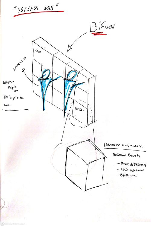
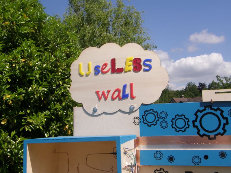
concept : useless wall.
This concept learns children about the basics of everything. It is an interactive wall where they can build, experiment, try things on. I want to include a couple af mechanics in the wall:
- Basic electronics
- basic mechanics
- basic programming
Design challeges:
- easy to use for children of all ages
- easy to transport
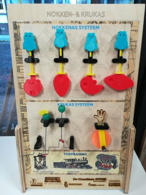
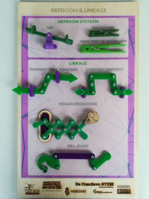
inspiration
In our makerspace we already have some tools for childres to experiment with. If possible I want to combine some of the excisting parts in the wall.
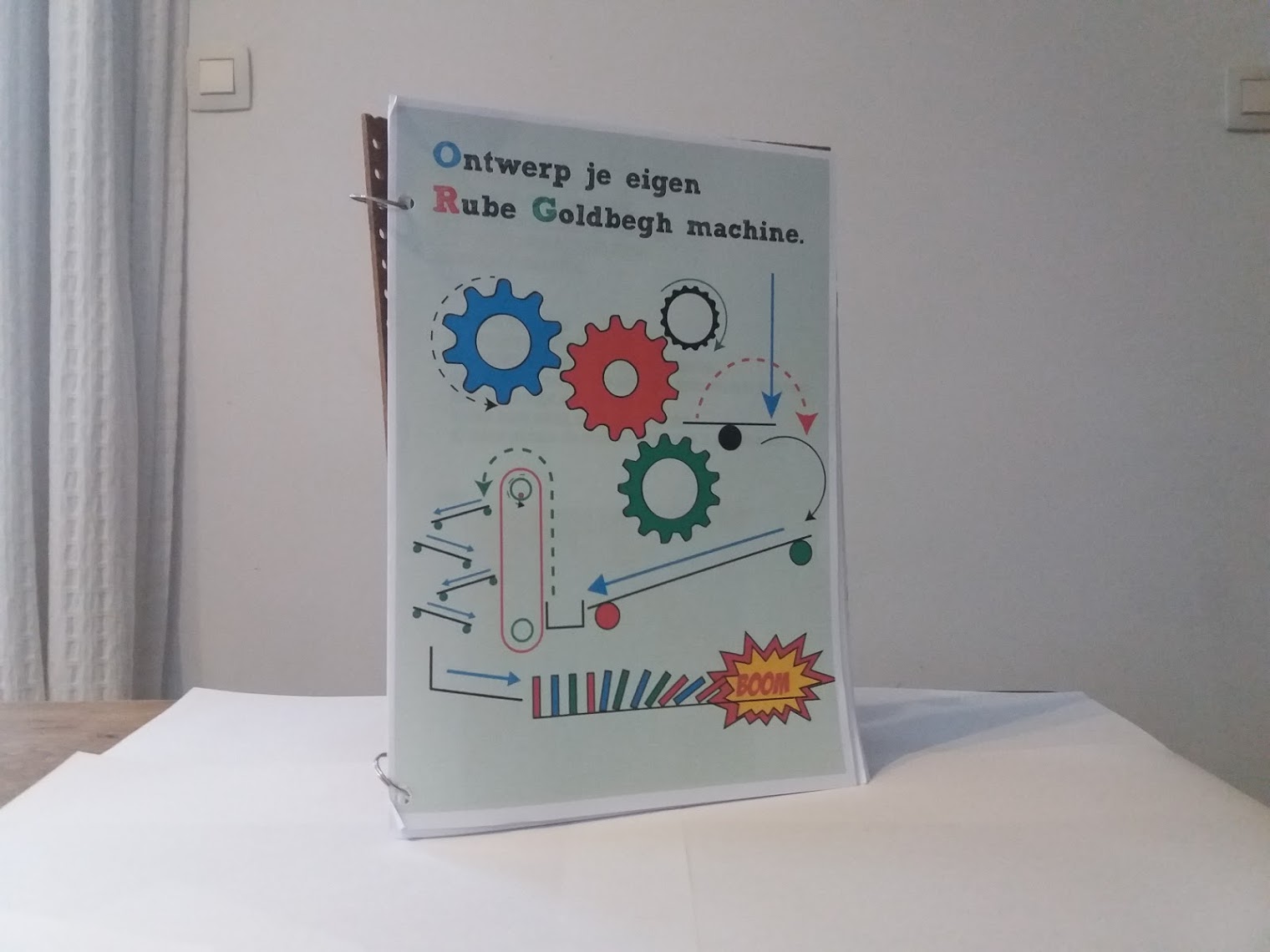
rube goldberg
Another big inspiration is the rube goldberg machine. A Rube Goldberg machine, named after American cartoonist Rube Goldberg, is a chain reaction-type machine or contraption intentionally designed to perform a simple task in an indirect and overly complicated way.
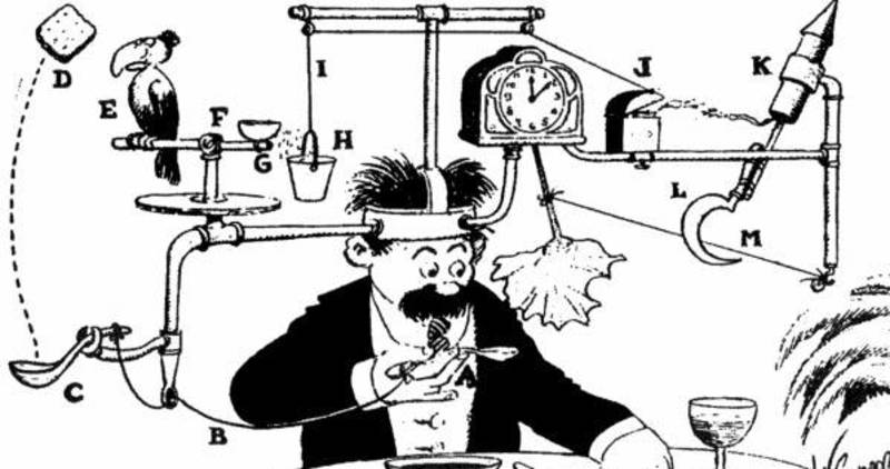
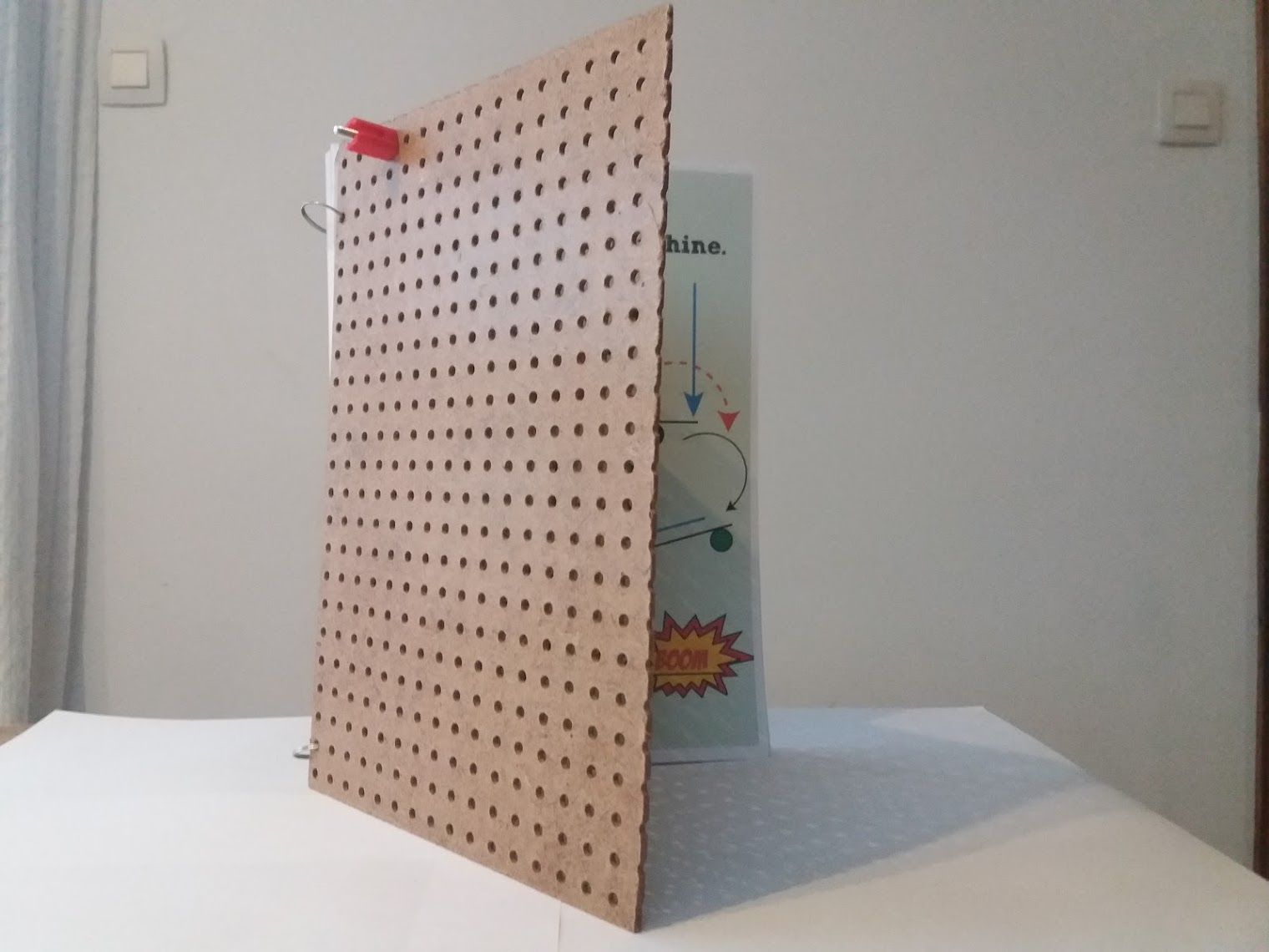
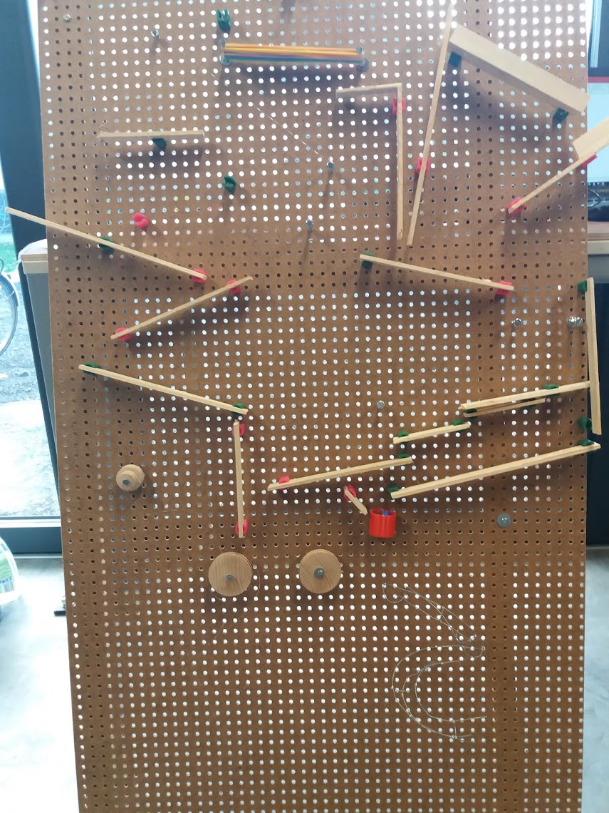
During my bachelor thesis I worked on a brainstorming method to design a rube goldbegh with children. this was inspired by the design cycle. the end result was a workbook through which the children step-by-step walked through each phase of a design cycle. This was mainly focused on mechanical steps that triggered a chain reaction.While designing, the children learned how to prototype quick and dirty and then convert these ideas using 3D printers and laser cutters. with this project I want to foccus on eletronische componenten.
creafix
Creafix is a project developed in collaboration with Howest by Fien Nelis, Marc Van Kerrebroeck, with coordination by Maria-Cristina Ciocci. Creafix grew out of a double need. On the one hand, the need for a tractor to take to promo events and where children can playfully experiment and rediscover science.On the other hand, the part where education is central. Compile a basic package with which schools can get started
Plan
Purpose of the end project.
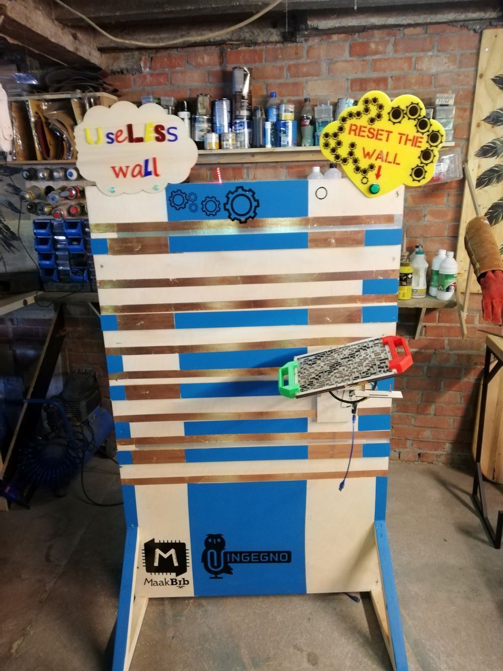
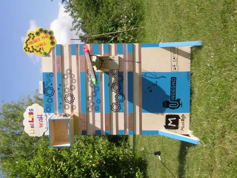
The final project will be a useless wall. The wall can be used stand alone, the intention is that participants have to solve a riddle in order to make the lights flash. There are 6 modules in the whole which form a separate system. Each system has a separate module that can be placed on the wall. Each module gives either a high or low signal. When all modules give a high signal, the lights will turn green. Each module contains a riddle that must be solved. If not all modules have been solved correctly (so not all give a high signal), the LED strip will only partially light up green. Below the places where all modules can be placed is a large board with the riddle on it. The wall is constructed in such a way that the modules can be replaced. The modular system ensures that the challenge can be changed by designing new modules. The only condition is that the module must give a high or low signal. The plan with this is to give the children the challenge during children’s camps in our lab to devise and make a new module.
What does it do?
The wall is useless, it is inspired by a rube Goldbergh machine. A rube goldberg machine is a chain reaction with the aim of often something very useless, for example popping a balloon. I wrote my bachelor thesis about a methodology to design this with children in order to introduce them to design and prototype techniques. In this case, all links in the chain were purely mechanical, with useless wall all parts will communicate with each other with electronic signals.
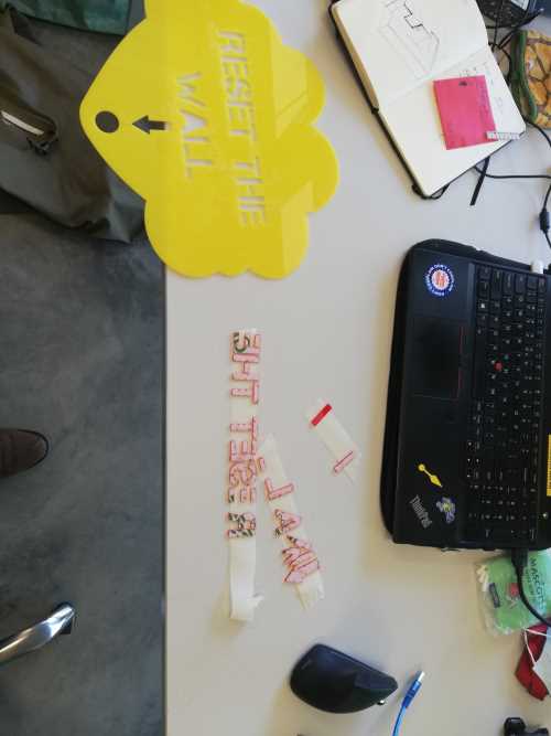
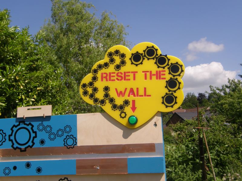
The useless wall is a product that can be used for 2 purposes, the first is entertainment at events. A number of modules can be placed on the wall. Each module is a puzzle or an assignment that can be solved by passers-by. If all parts are solved correctly, all lights will turn green. Afterwards, the wall can be reset by pressing the large reset button.
The other great function of this wall is to be able to use it during holiday camps here in the fablab. We organize a number of summer camps for children here on each face. During such a camp, children learn to work with digital tools by completing various assignments. My idea is to use this wall for this. Each camp participant will have to design and create their own module that can be hung on the wall. For this they have to use different techniques and machines and a part of programming will also be discussed. I think it would be nice that many techniques are discussed and the participants can fully develop their own idea. For this, they must adhere to the pre-imposed design rules.
Who’s done what beforehand?
The idea arose from my bachelor thesis a few years ago, when I had designed a design methodology for children. This was applied to the design and manufacture of a rube goldbergh machine. The focus was on learning to design. As a designer and maker, I personally think it is very important that everyone is taught a certain method when it comes to making things. My thesis at the time consisted of a wall and a fill-in book for the children who help build it. Techniques discussed here were mainly quick and dirty prototypes and 3D printing. Because I have already mastered more techniques, I thought it was a nice idea to go a step further. The approach is therefore not completely the same, but similar.
What did you design?
I desiged almost everything on the wall. i want to revere to my project page where you can follow every step of all the parts i desiged
- the wall itself
- module one: nerve spiral
- module two : the maze
- connection between the modules and the wall
- all the connection pieces
What materials and components were used?
the wall
- one arduino
- 10 meter copper tape
- plywood 2440mmx1220mmx12mm
- one neopixel of 8 pixels
- one retrobutton
- 6 meter wooden beam 44mmx44mm
- a couple of screws
- 5 meter electrical cable in diffirent colour
- plexi plate 900mmx600mmx4mm can be coloured acrylic as well
- plywood 900mmx600mmx4mm
module one: nerve spiral
- one arduine
- plywood 100mmx100mmx12mm
- one neopixel of 8 pixels
- one buzzer
- copper tabe 30 cm
- copper wire 40 cm
- electrical wire 2 meter in different colour
module two : the maze
- one ardiuno nano
- plywood 300mmx200mmx12mm
- copper tape 30 cm
- one neopixel
- elektrical wire
Where did they come from?
The wood come from a local wood vendor Wood and plexi for the lasercutter comes from opitec Vinyl comes from the feerieke All electronic parts come from a local electroshop
What processes were used?
I have almost used every technique that you can find in the lab:
- lasercutting
- 3D printing
- cnc milling
- vinylcutter
- programming
- woodworking
- a little bit of welding
- 3D drawing ( fusion360)
- 2D drawing
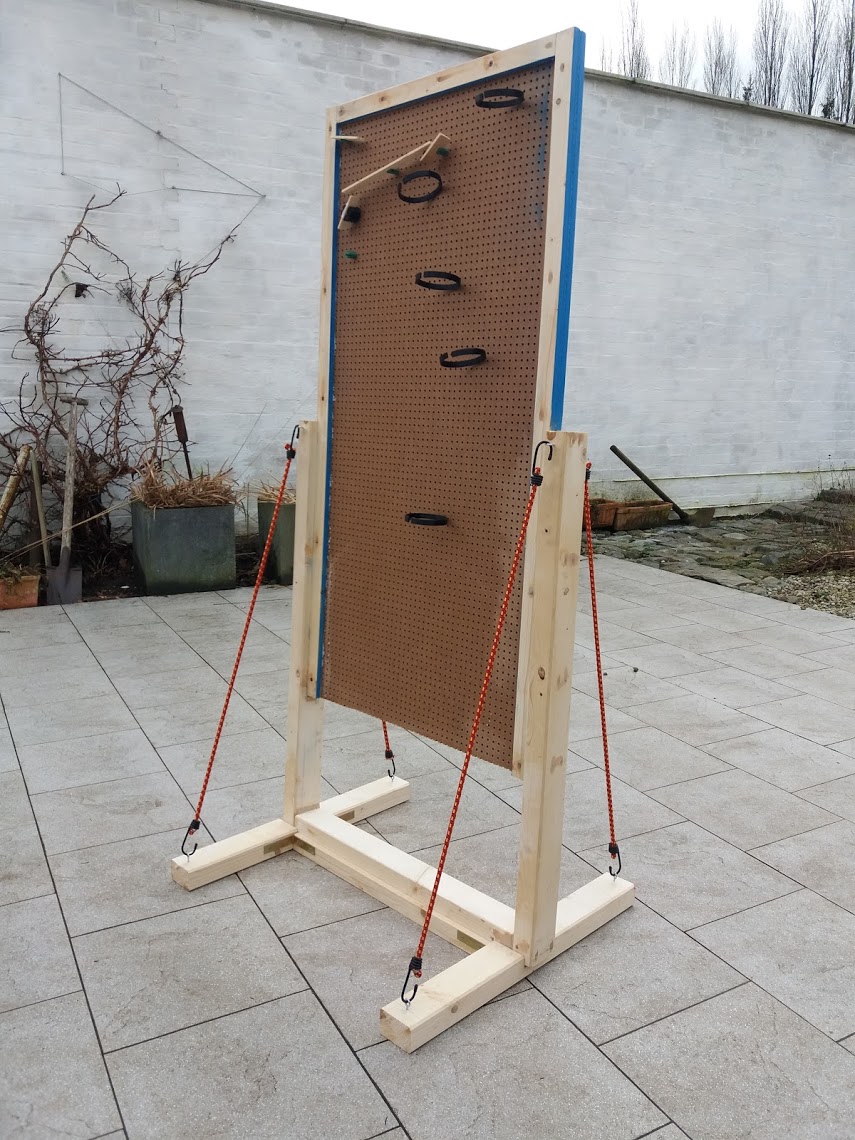
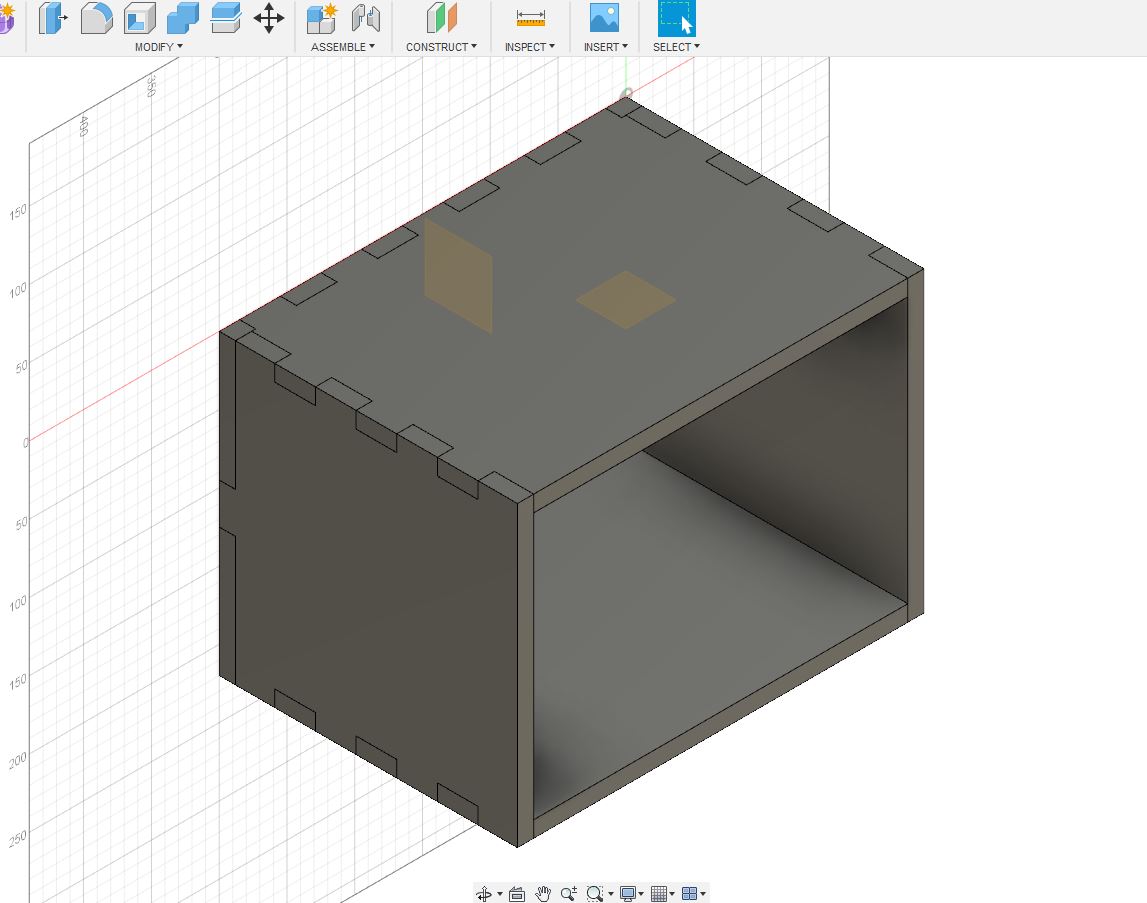
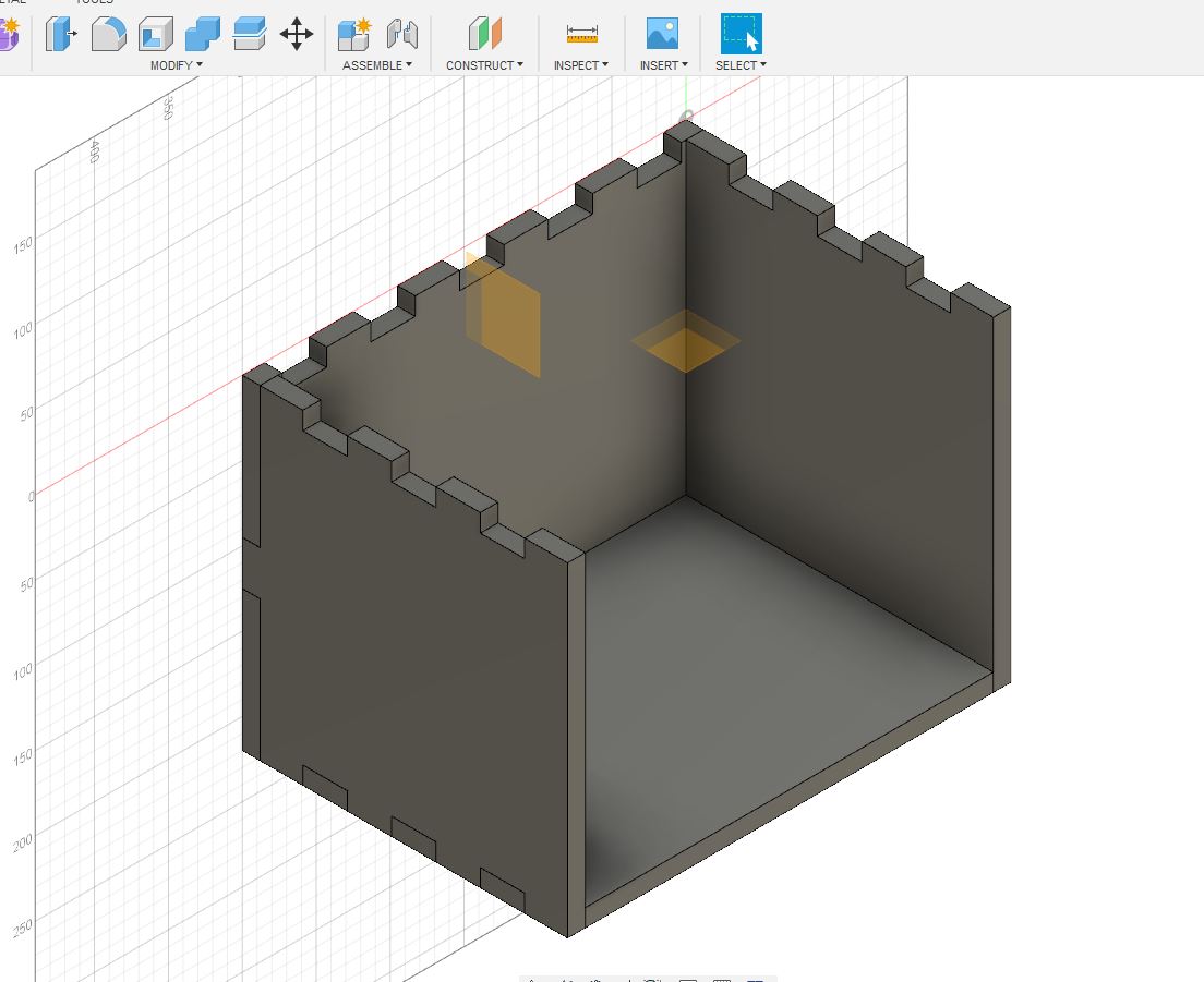
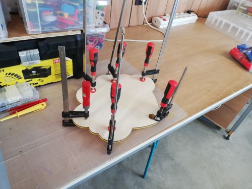
making the structure
I first started with designing the Wall structure. I started working out the structure of the wall. The wall and feet are made manually. The boxes that are placed on the wall and form a subsystem. I will make the boxes with the CNC machine.
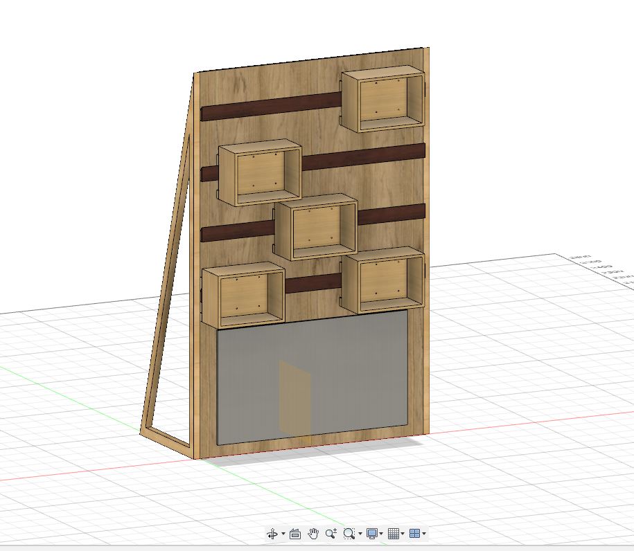
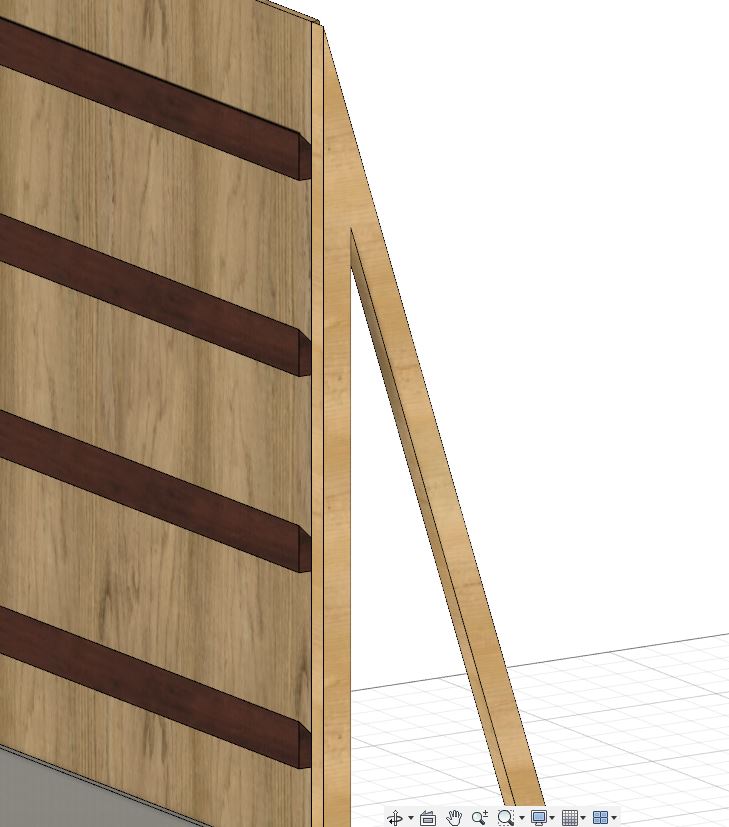
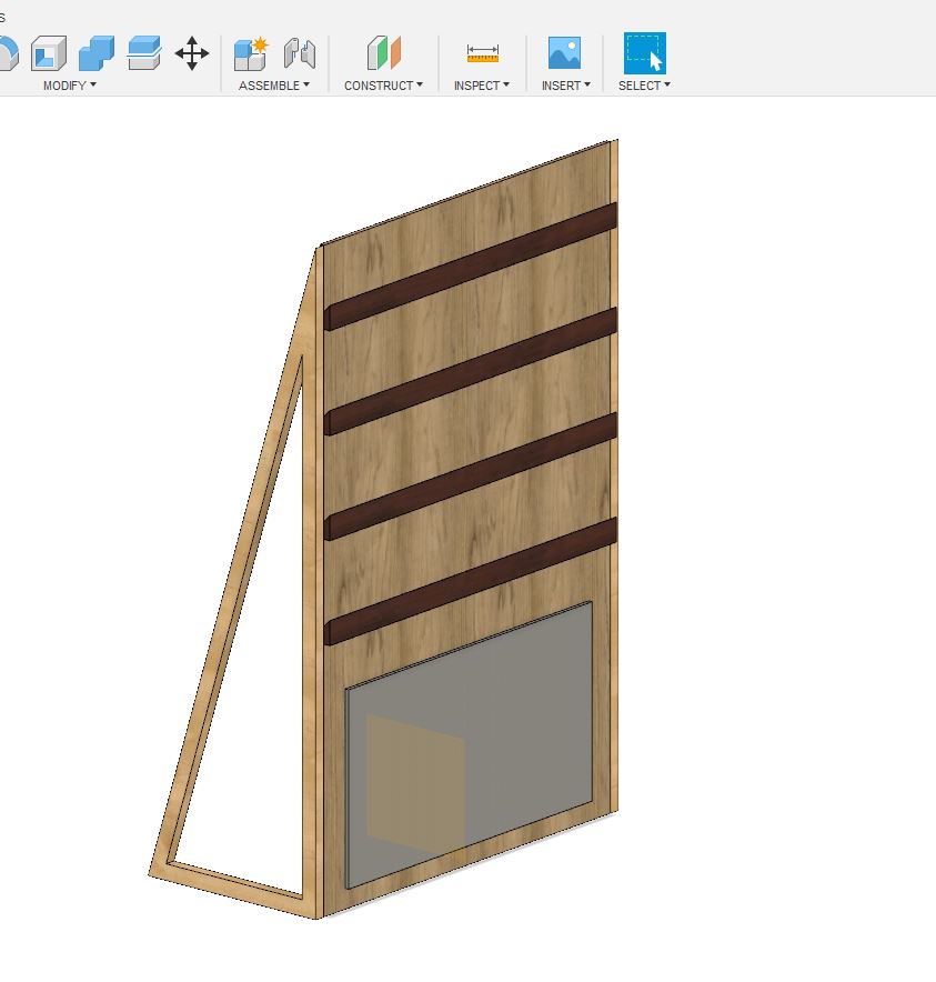
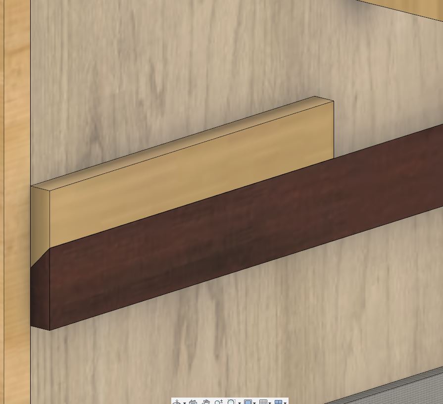
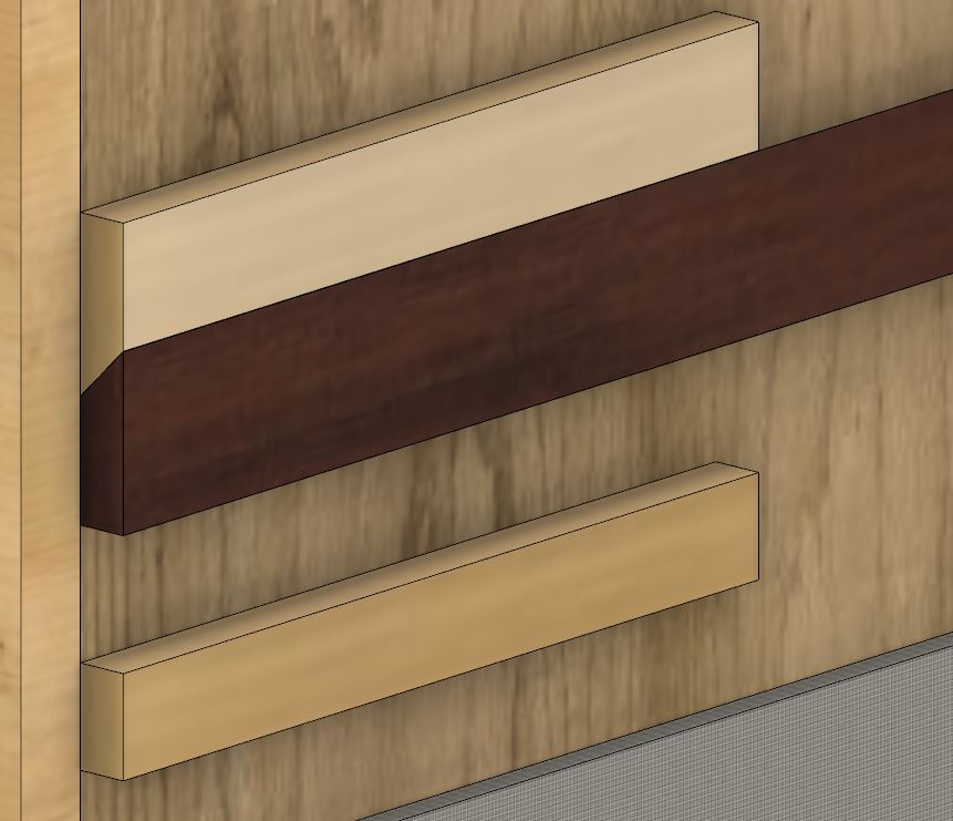
The mounting system is inspired by a French tool wall.
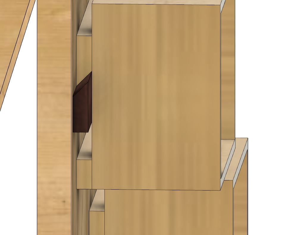
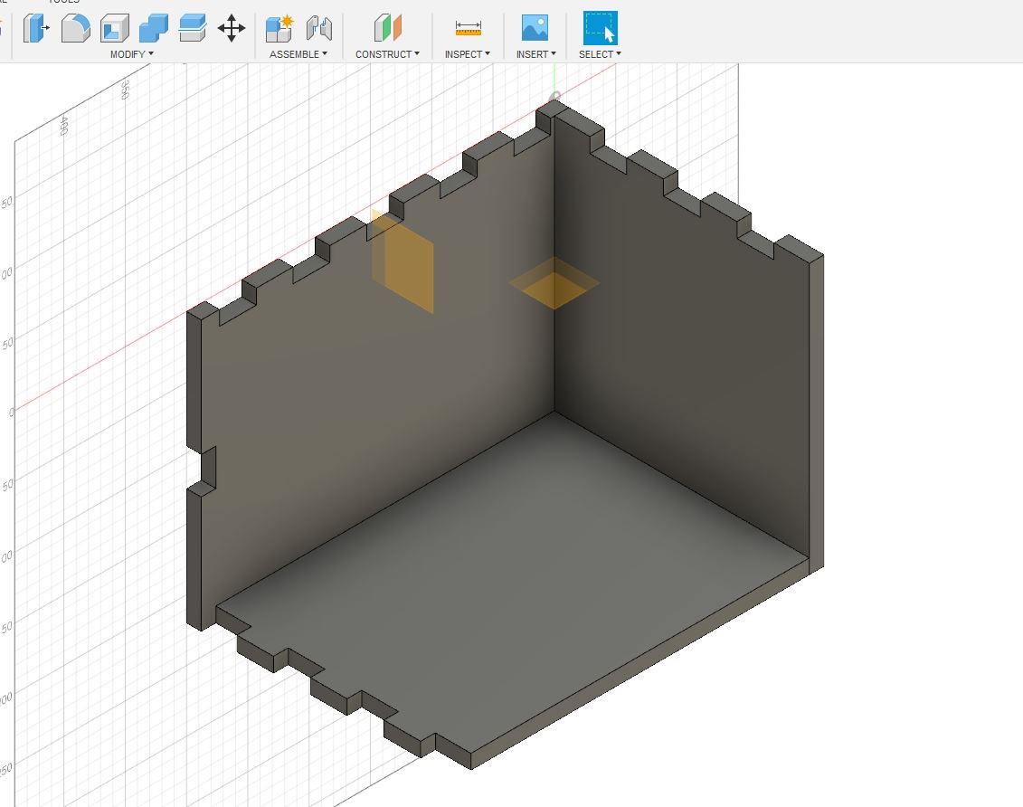
the boxes
the system
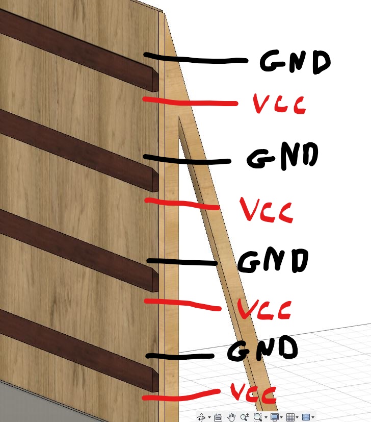
Each line where a box can be attached contains two lines to which the box can connect, if the box gives a high signal it is picked up by the general system and can be processed. It is important that the box only gives a high or low signal.
subsystems.
Each box is a system in itself, these are my ideas to put in each box.
1 guess the correct color with color sensor 2 Solve the maze 3 electro game 4… 5… 6…
design proces.
I started with designing the diffirent parts of the wall, we can divide it in different modules:
- the wall
- module one : nerve spiral
- module two electromaze.
the wall
I started to design the wall in fusion360.
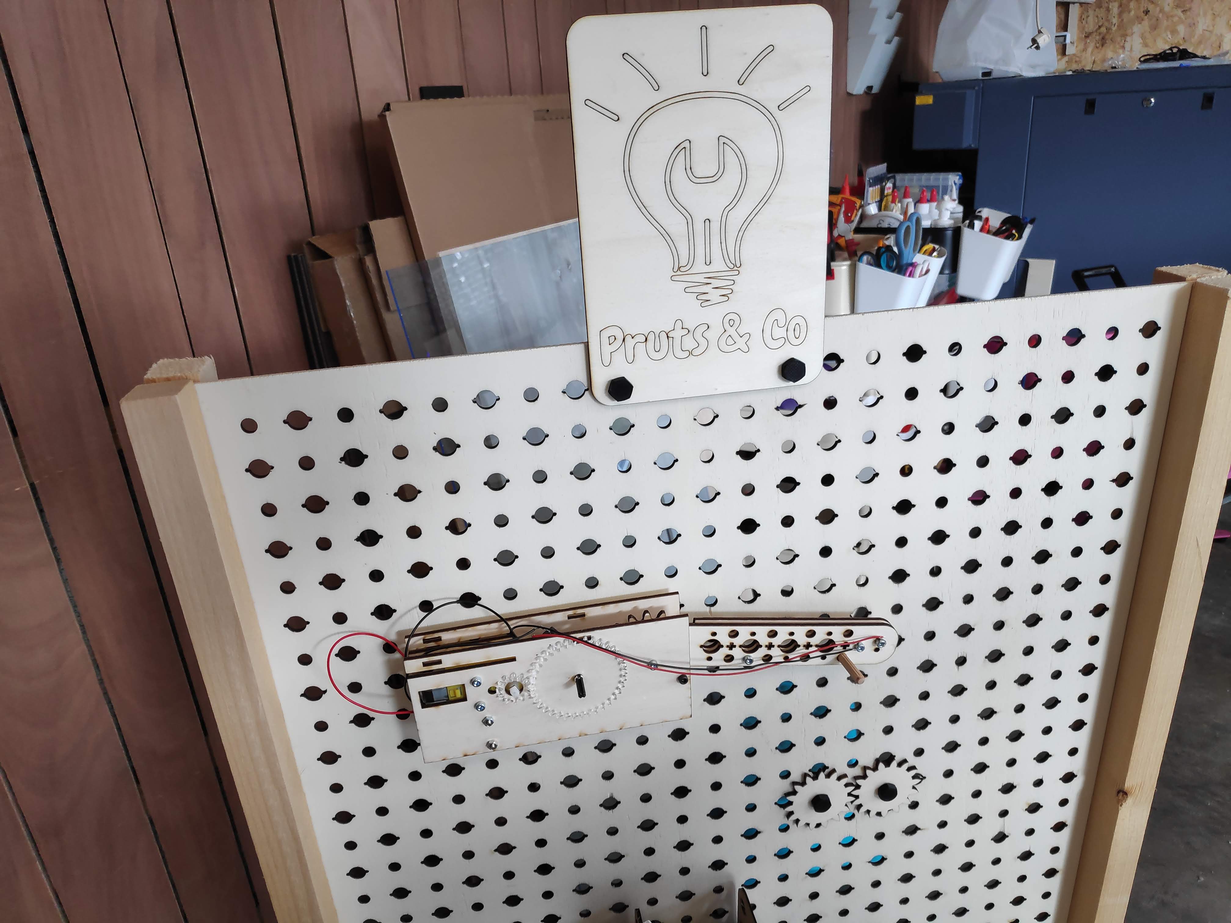
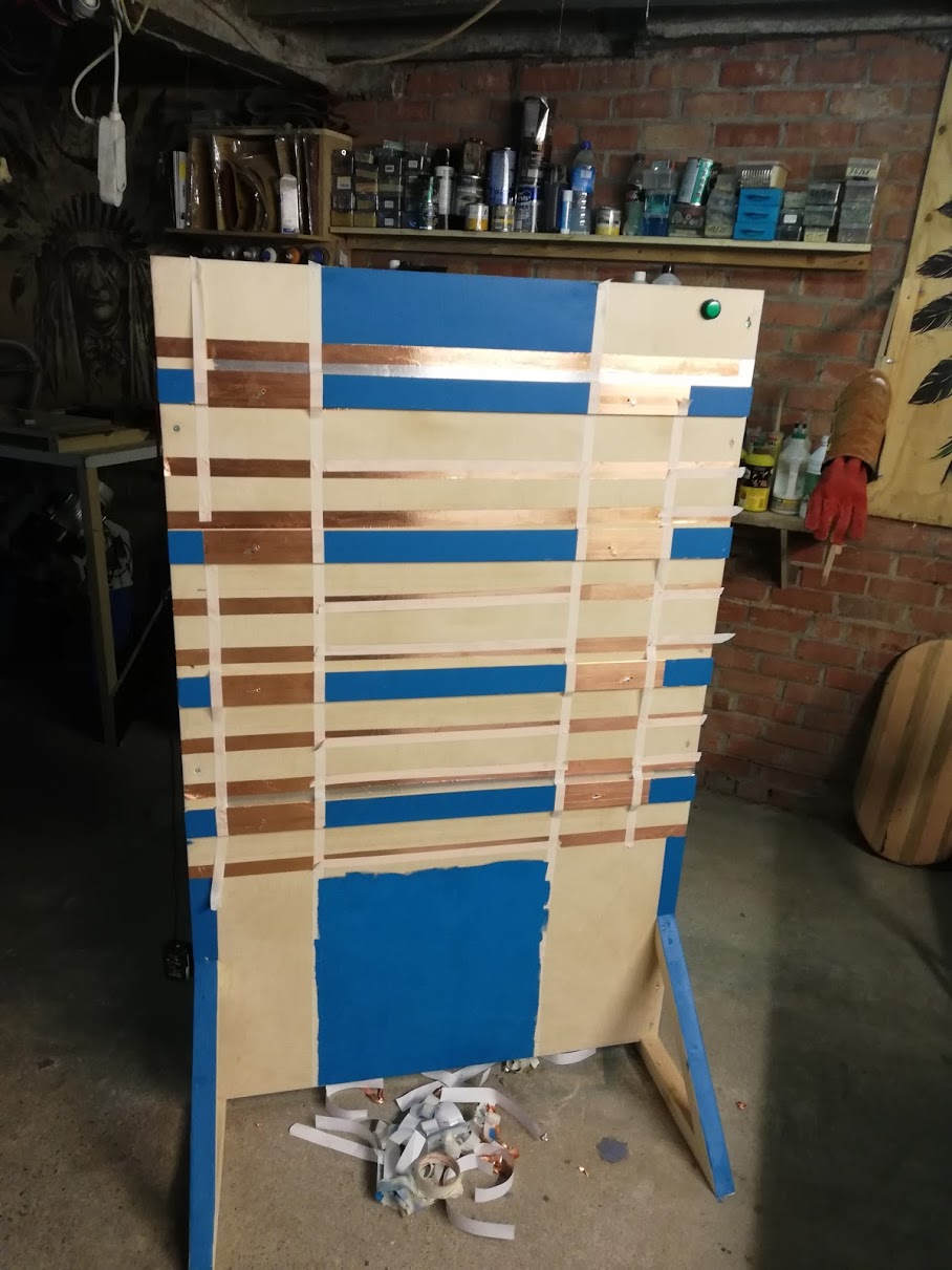
When this part was desiged i started in my woodshop on making the wall. For this part I did not use digital machines . When the structure was ready I gave it some colour and added the copper tape
machines i used:
- table saw
- nail gun
- sanding machine
- crosscut saw
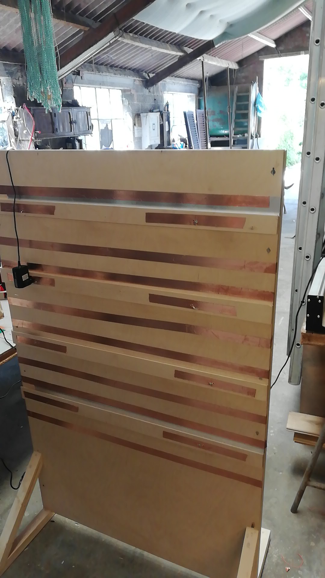
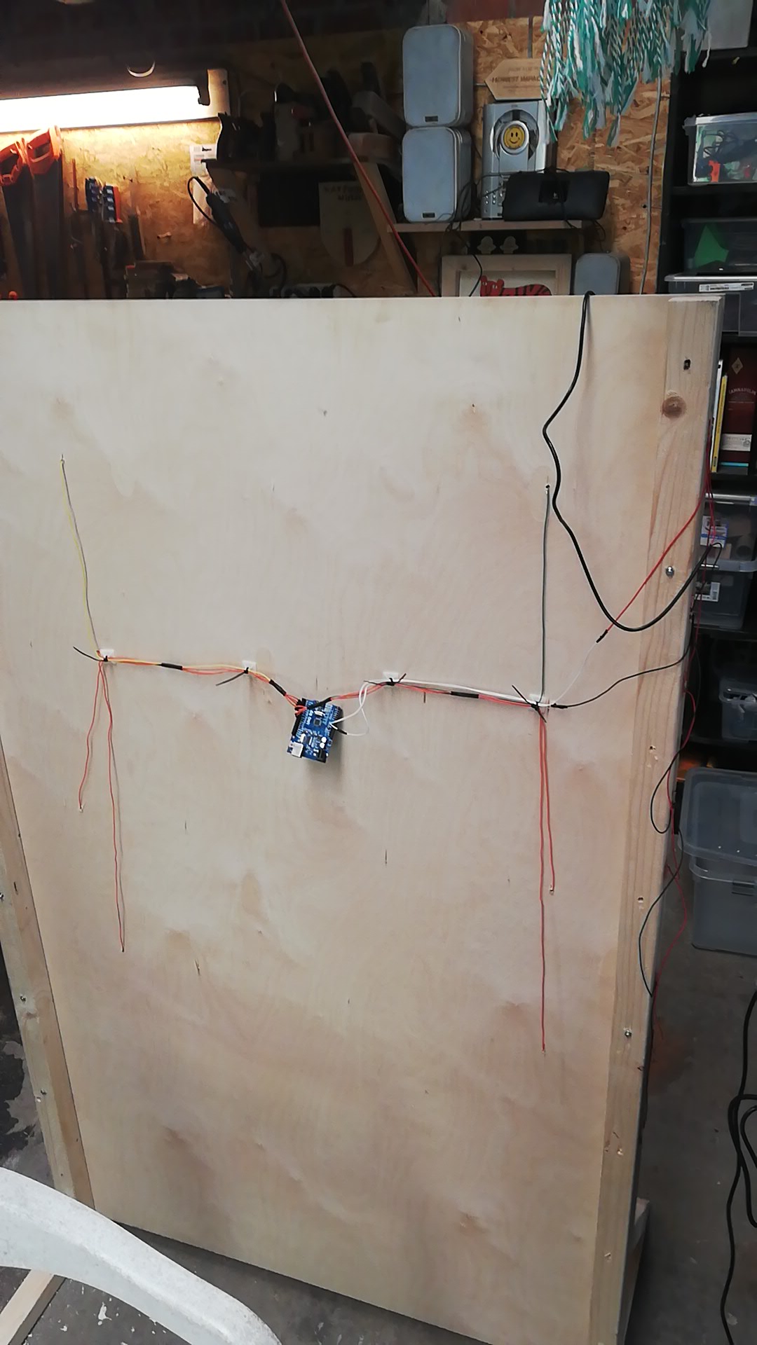
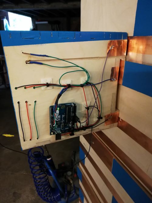
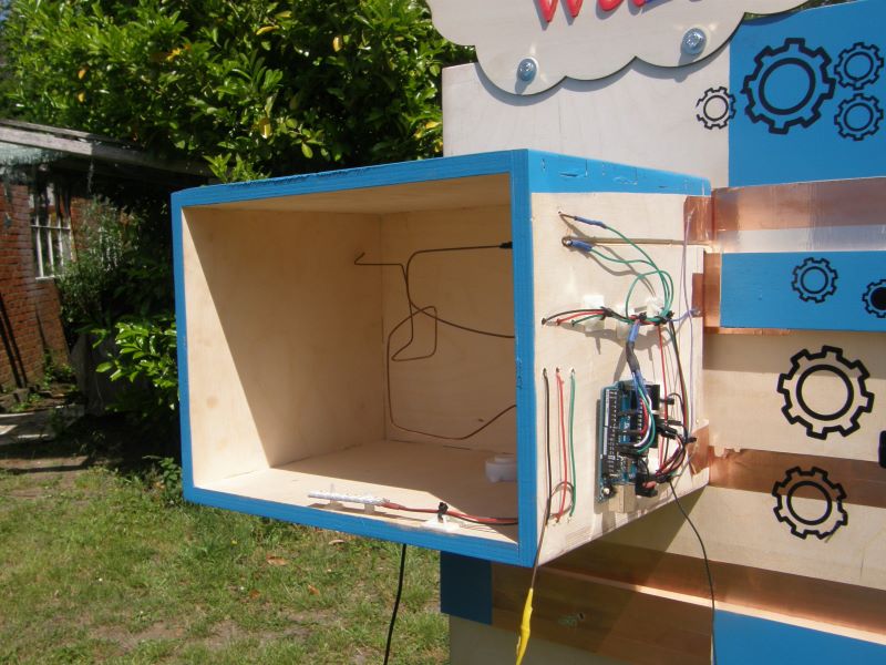
When this was ready I started to solder the connections on the back of the wall. There is place on the wall for 8 module each module gets one pin on the arduino board. On the wall there are also lines for ground and VCC. each line gets 5V.
Then I started the write the code for the arduino on the back of the wall. I used our own blokkencode. I used this interface for programming the board for 2 reasons; the first is because we use this when we program with kids.
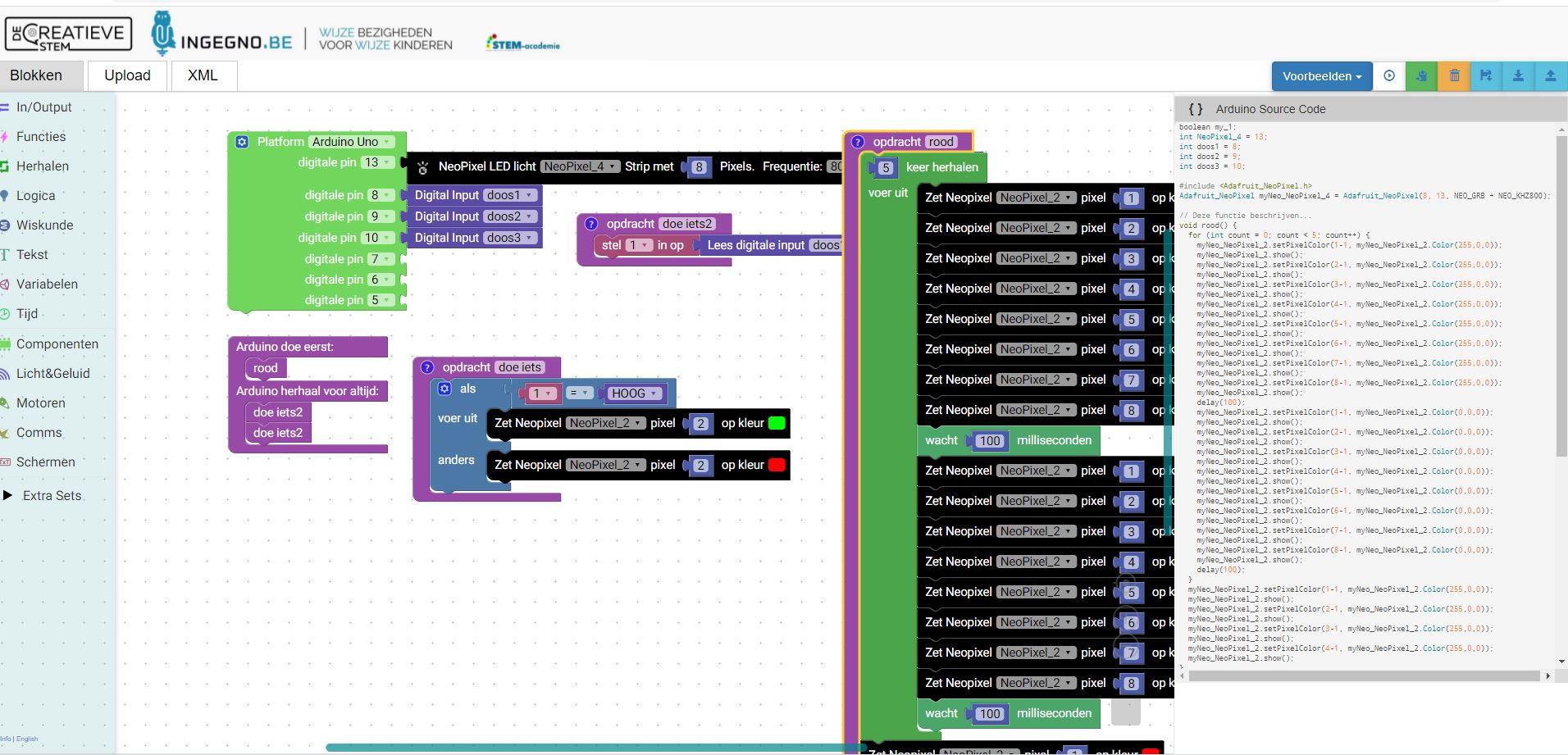
I used this code for the arduino:
boolean my_1;
int NeoPixel_3 = 13;
int doos1 = 8;
int doos2 = 9;
int doos3 = 10;

#include <Adafruit_NeoPixel.h>
Adafruit_NeoPixel myNeo_NeoPixel_3 = Adafruit_NeoPixel(8, 13, NEO_GRB + NEO_KHZ800);

// Deze functie beschrijven...
void rood() {
  for (int count = 0; count < 5; count++) {
    myNeo_NeoPixel_2.setPixelColor(1-1, myNeo_NeoPixel_2.Color(255,0,0));
    myNeo_NeoPixel_2.show();
    myNeo_NeoPixel_2.setPixelColor(2-1, myNeo_NeoPixel_2.Color(255,0,0));
    myNeo_NeoPixel_2.show();
    myNeo_NeoPixel_2.setPixelColor(3-1, myNeo_NeoPixel_2.Color(255,0,0));
    myNeo_NeoPixel_2.show();
    myNeo_NeoPixel_2.setPixelColor(4-1, myNeo_NeoPixel_2.Color(255,0,0));
    myNeo_NeoPixel_2.show();
    myNeo_NeoPixel_2.setPixelColor(5-1, myNeo_NeoPixel_2.Color(255,0,0));
    myNeo_NeoPixel_2.show();
    myNeo_NeoPixel_2.setPixelColor(6-1, myNeo_NeoPixel_2.Color(255,0,0));
    myNeo_NeoPixel_2.show();
    myNeo_NeoPixel_2.setPixelColor(7-1, myNeo_NeoPixel_2.Color(255,0,0));
    myNeo_NeoPixel_2.show();
    myNeo_NeoPixel_2.setPixelColor(8-1, myNeo_NeoPixel_2.Color(255,0,0));
    myNeo_NeoPixel_2.show();
    delay(100);
    myNeo_NeoPixel_2.setPixelColor(1-1, myNeo_NeoPixel_2.Color(0,0,0));
    myNeo_NeoPixel_2.show();
    myNeo_NeoPixel_2.setPixelColor(2-1, myNeo_NeoPixel_2.Color(0,0,0));
    myNeo_NeoPixel_2.show();
    myNeo_NeoPixel_2.setPixelColor(3-1, myNeo_NeoPixel_2.Color(0,0,0));
    myNeo_NeoPixel_2.show();
    myNeo_NeoPixel_2.setPixelColor(4-1, myNeo_NeoPixel_2.Color(0,0,0));
    myNeo_NeoPixel_2.show();
    myNeo_NeoPixel_2.setPixelColor(5-1, myNeo_NeoPixel_2.Color(0,0,0));
    myNeo_NeoPixel_2.show();
    myNeo_NeoPixel_2.setPixelColor(6-1, myNeo_NeoPixel_2.Color(0,0,0));
    myNeo_NeoPixel_2.show();
    myNeo_NeoPixel_2.setPixelColor(7-1, myNeo_NeoPixel_2.Color(0,0,0));
    myNeo_NeoPixel_2.show();
    myNeo_NeoPixel_2.setPixelColor(8-1, myNeo_NeoPixel_2.Color(0,0,0));
    myNeo_NeoPixel_2.show();
    delay(100);
  }
  myNeo_NeoPixel_2.setPixelColor(1-1, myNeo_NeoPixel_2.Color(255,0,0));
  myNeo_NeoPixel_2.show();
  myNeo_NeoPixel_2.setPixelColor(2-1, myNeo_NeoPixel_2.Color(255,0,0));
  myNeo_NeoPixel_2.show();
  myNeo_NeoPixel_2.setPixelColor(3-1, myNeo_NeoPixel_2.Color(255,0,0));
  myNeo_NeoPixel_2.show();
  myNeo_NeoPixel_2.setPixelColor(4-1, myNeo_NeoPixel_2.Color(255,0,0));
  myNeo_NeoPixel_2.show();
}

// Deze functie beschrijven...
void doe_iets2() {
  my_1 = digitalRead(doos1);
}

// Deze functie beschrijven...
void doe_iets() {
  if (my_1 == HIGH) {
    myNeo_NeoPixel_2.setPixelColor(2-1, myNeo_NeoPixel_2.Color(0,255,0));
    myNeo_NeoPixel_2.show();
  } else {
    myNeo_NeoPixel_2.setPixelColor(2-1, myNeo_NeoPixel_2.Color(255,0,0));
    myNeo_NeoPixel_2.show();
  }
}


void setup() {
  myNeo_NeoPixel_3.begin();
  myNeo_NeoPixel_3.show();
  pinMode(doos1, INPUT);
  pinMode(doos2, INPUT);
  pinMode(doos3, INPUT);

  rood();

}

void loop() {
  doe_iets2();
  doe_iets2();

}
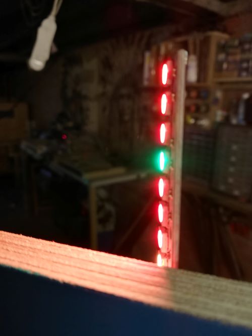
What the code does is the following:
Each module give a high signal when it is solved correctely, when the master recieves a high signal it will turn one off the pixel off the neopixel green in stead off red. There is also a reset button to start the wall again.
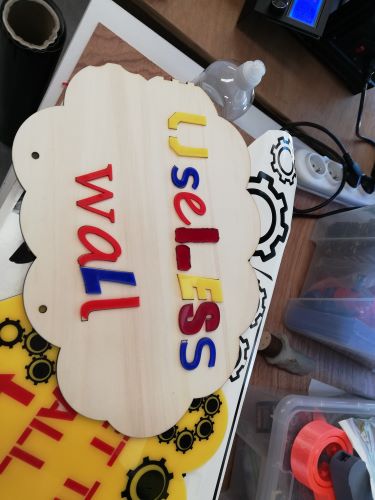
decorating the wall
Because the main users off the wall will be children (off all ages) it should also be fun to look at and not a boring wall with a couple of wires in it.
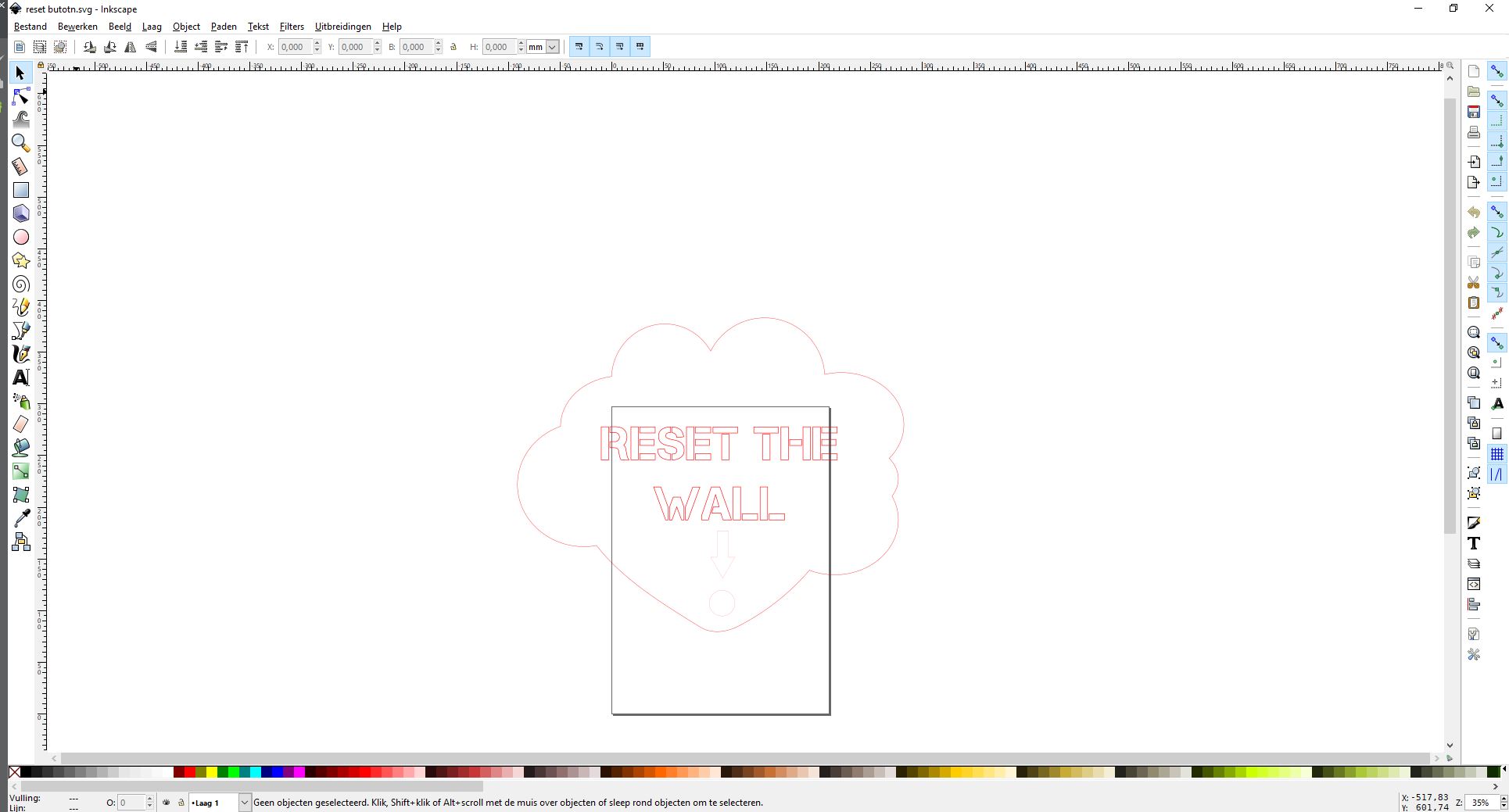
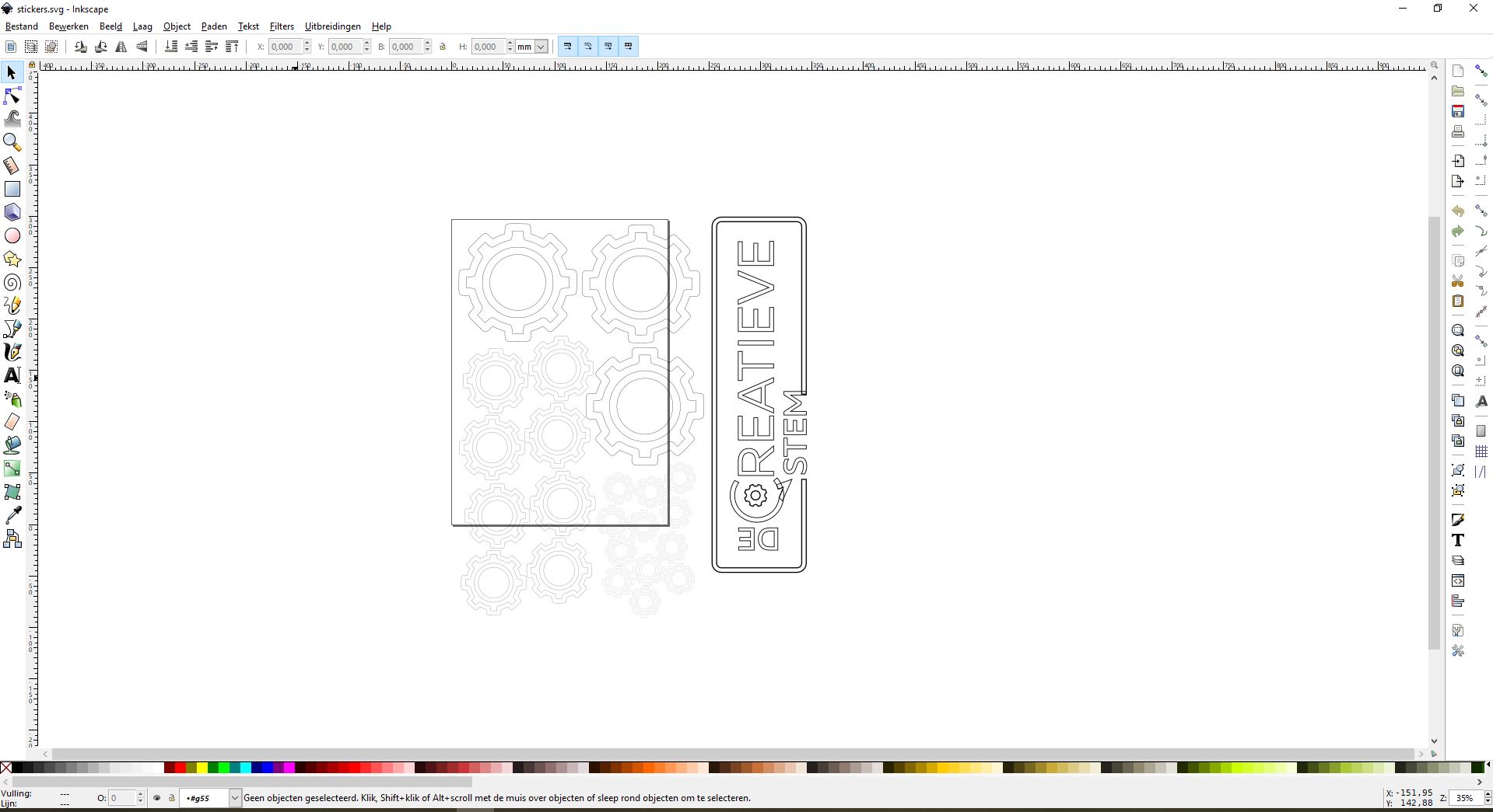
I used the lasercutter and vinyl cutter for this. I designed this in inkscape.
The first two i made with the lasercutter out of plexi.
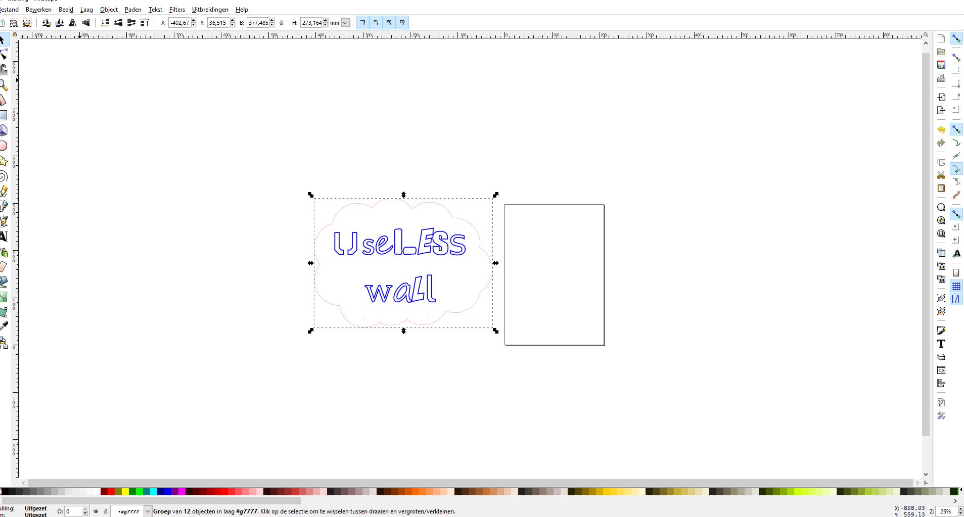
I used these designes to cut them in different colours and then glued them together.
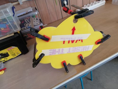
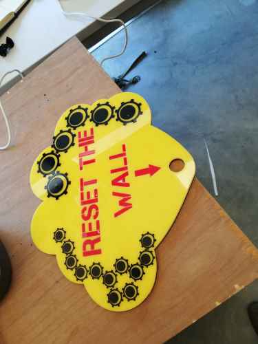
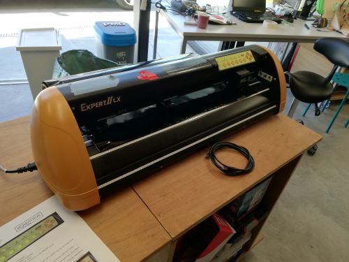
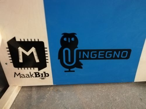
I also made a couple of stickers with the vinyl cutter, I drawed some gears and all the logos of the lab here in gent.
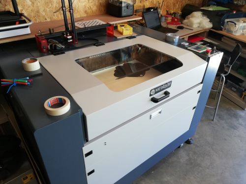
For the lasercutting part i use a metaquip I talk about this machine in the assigment of week 4.
I used 2 different cutting machines the first was a big one but the knive broke during the cutting.
I put everything on the wall.
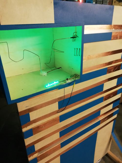
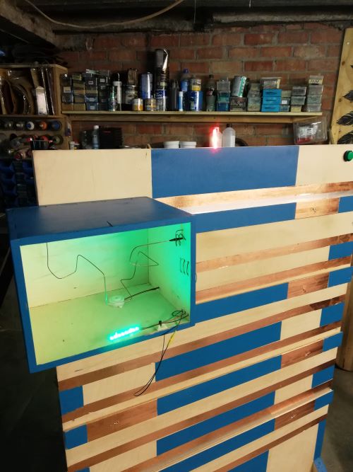
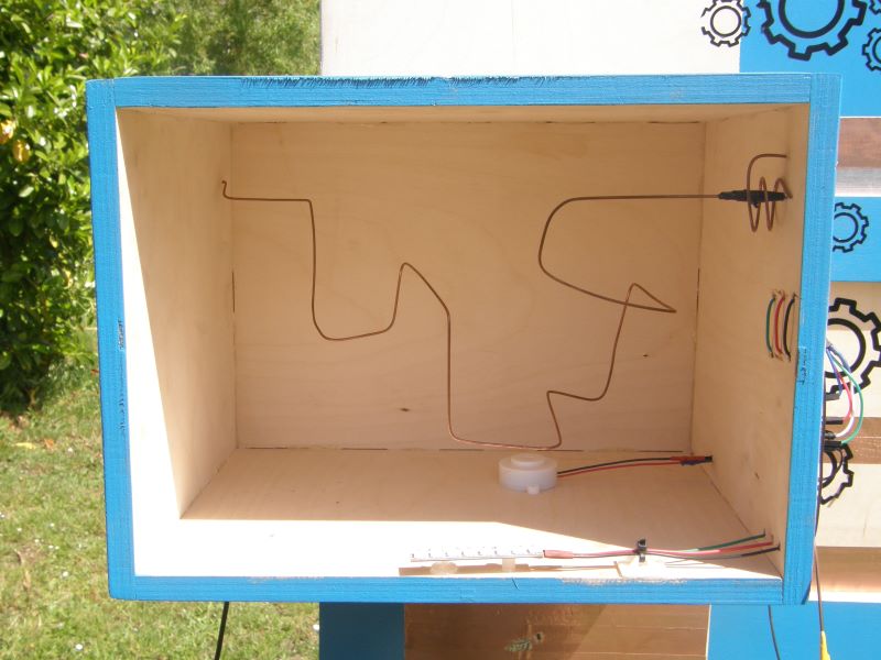
module one: nerve spiral.
For this part i used a cnc milling machine. I used the shapeoke3 which i explaned in week 3. First i designed it in fusion360 , it is made parametrecly , this way it can be used with other plywood with a diffirent thicness.
Inside the box is a nerve spiral made out of a copper wire . The goal of this game is to follow the spiral without touching it. When you touch the spiral the neopixel flickers red and the buzzer makes a irritating noice. When the participant is able to solve the spiral it touches another copper wire and the neopixel turn green and the module give a high signal to the master. The box also contains an arduino to guide everything.
I programmed this module also with the blokkencode. this module has the
boolean my_1;
boolean my_2;
boolean my_3;
boolean my_4;
boolean my_5;
boolean my_6;
boolean my_7;
boolean my_8;
int NeoPixel_2 = 13;
int doos1 = 2;
int doos2 = 3;
int doos3 = 4;
int doos4 = 5;
int doos5 = 6;
int doos6 = 7;
int doos7 = 8;
int doos8 = 9;
int Drukknop1 = 10;

#include <Adafruit_NeoPixel.h>
Adafruit_NeoPixel myNeo_NeoPixel_2 = Adafruit_NeoPixel(8, 13, NEO_GRB + NEO_KHZ800);
boolean Drukknop1_PRESSED = LOW;

long Drukknop1buttonTimer = 0;
#define Drukknop1minShortPressTime 80
#define Drukknop1longPressTime 750
boolean Drukknop1buttonActive = false;
boolean Drukknop1longPressActive = false;
#define Drukknop1NOPRESS    0
#define Drukknop1SHORTPRESS 1
#define Drukknop1LONGPRESS  2
int Drukknop1PressType = Drukknop1NOPRESS;


void handleDrukknop1Press() {
  Drukknop1PressType = Drukknop1NOPRESS;
      if (digitalRead(Drukknop1) == Drukknop1_PRESSED) {
        if (Drukknop1buttonActive == false) {
          Drukknop1buttonActive = true;
          Drukknop1buttonTimer = millis();
        }
        if ((millis() - Drukknop1buttonTimer > Drukknop1longPressTime) && (Drukknop1longPressActive == false)) {
          Drukknop1longPressActive = true;
          Drukknop1PressType = Drukknop1LONGPRESS;
        }
      } else {
        if (Drukknop1buttonActive == true) {
          if (Drukknop1longPressActive == true) {
            Drukknop1longPressActive = false;
          } else {
            //avoid fast fluctuations to be identified as a click
            if (millis() - Drukknop1buttonTimer > Drukknop1minShortPressTime)
              Drukknop1PressType = Drukknop1SHORTPRESS;
          }
          Drukknop1buttonActive = false;
        }
      }
}


// Deze functie beschrijven...
void uitput() {
  if (my_1 == HIGH) {
    myNeo_NeoPixel_2.setPixelColor(1-1, myNeo_NeoPixel_2.Color(0,255,0));
    myNeo_NeoPixel_2.show();
  } else {
    myNeo_NeoPixel_2.setPixelColor(1-1, myNeo_NeoPixel_2.Color(255,0,0));
    myNeo_NeoPixel_2.show();
  }
  if (my_2 == HIGH) {
    myNeo_NeoPixel_2.setPixelColor(2-1, myNeo_NeoPixel_2.Color(0,255,0));
    myNeo_NeoPixel_2.show();
  } else {
    myNeo_NeoPixel_2.setPixelColor(2-1, myNeo_NeoPixel_2.Color(255,0,0));
    myNeo_NeoPixel_2.show();
  }
  if (my_3 == HIGH) {
    myNeo_NeoPixel_2.setPixelColor(3-1, myNeo_NeoPixel_2.Color(0,255,0));
    myNeo_NeoPixel_2.show();
  } else {
    myNeo_NeoPixel_2.setPixelColor(3-1, myNeo_NeoPixel_2.Color(255,0,0));
    myNeo_NeoPixel_2.show();
  }
  if (my_4 == HIGH) {
    myNeo_NeoPixel_2.setPixelColor(4-1, myNeo_NeoPixel_2.Color(0,255,0));
    myNeo_NeoPixel_2.show();
  } else {
    myNeo_NeoPixel_2.setPixelColor(4-1, myNeo_NeoPixel_2.Color(255,0,0));
    myNeo_NeoPixel_2.show();
  }
  if (my_5 == HIGH) {
    myNeo_NeoPixel_2.setPixelColor(5-1, myNeo_NeoPixel_2.Color(0,255,0));
    myNeo_NeoPixel_2.show();
  } else {
    myNeo_NeoPixel_2.setPixelColor(5-1, myNeo_NeoPixel_2.Color(255,0,0));
    myNeo_NeoPixel_2.show();
  }
  if (my_6 == HIGH) {
    myNeo_NeoPixel_2.setPixelColor(6-1, myNeo_NeoPixel_2.Color(0,255,0));
    myNeo_NeoPixel_2.show();
  } else {
    myNeo_NeoPixel_2.setPixelColor(6-1, myNeo_NeoPixel_2.Color(255,0,0));
    myNeo_NeoPixel_2.show();
  }
  if (my_7 == HIGH) {
    myNeo_NeoPixel_2.setPixelColor(7-1, myNeo_NeoPixel_2.Color(0,255,0));
    myNeo_NeoPixel_2.show();
  } else {
    myNeo_NeoPixel_2.setPixelColor(7-1, myNeo_NeoPixel_2.Color(255,0,0));
    myNeo_NeoPixel_2.show();
  }
  if (my_8 == HIGH) {
    myNeo_NeoPixel_2.setPixelColor(8-1, myNeo_NeoPixel_2.Color(0,255,0));
    myNeo_NeoPixel_2.show();
  } else {
    myNeo_NeoPixel_2.setPixelColor(8-1, myNeo_NeoPixel_2.Color(255,0,0));
    myNeo_NeoPixel_2.show();
  }
  handleDrukknop1Press();

  if (Drukknop1PressType == Drukknop1SHORTPRESS) {
    //START STATEMENTS SHORT PRESS
    rood();
    //END  STATEMENTS SHORT PRESS
  } else if (Drukknop1PressType == Drukknop1LONGPRESS) {
    //START STATEMENTS LONG PRESS
    //END  STATEMENTS LONG PRESS
  } else if (!Drukknop1longPressActive && digitalRead(Drukknop1) == Drukknop1_PRESSED) {
    //START STATEMENTS PRESS
    //END  STATEMENTS PRESS
  }

}

// Deze functie beschrijven...
void rood() {
  for (int count = 0; count < 5; count++) {
    myNeo_NeoPixel_2.setPixelColor(1-1, myNeo_NeoPixel_2.Color(255,0,0));
    myNeo_NeoPixel_2.show();
    myNeo_NeoPixel_2.setPixelColor(2-1, myNeo_NeoPixel_2.Color(255,0,0));
    myNeo_NeoPixel_2.show();
    myNeo_NeoPixel_2.setPixelColor(3-1, myNeo_NeoPixel_2.Color(255,0,0));
    myNeo_NeoPixel_2.show();
    myNeo_NeoPixel_2.setPixelColor(4-1, myNeo_NeoPixel_2.Color(255,0,0));
    myNeo_NeoPixel_2.show();
    myNeo_NeoPixel_2.setPixelColor(5-1, myNeo_NeoPixel_2.Color(255,0,0));
    myNeo_NeoPixel_2.show();
    myNeo_NeoPixel_2.setPixelColor(6-1, myNeo_NeoPixel_2.Color(255,0,0));
    myNeo_NeoPixel_2.show();
    myNeo_NeoPixel_2.setPixelColor(7-1, myNeo_NeoPixel_2.Color(255,0,0));
    myNeo_NeoPixel_2.show();
    myNeo_NeoPixel_2.setPixelColor(8-1, myNeo_NeoPixel_2.Color(255,0,0));
    myNeo_NeoPixel_2.show();
    delay(100);
    myNeo_NeoPixel_2.setPixelColor(1-1, myNeo_NeoPixel_2.Color(0,0,0));
    myNeo_NeoPixel_2.show();
    myNeo_NeoPixel_2.setPixelColor(2-1, myNeo_NeoPixel_2.Color(0,0,0));
    myNeo_NeoPixel_2.show();
    myNeo_NeoPixel_2.setPixelColor(3-1, myNeo_NeoPixel_2.Color(0,0,0));
    myNeo_NeoPixel_2.show();
    myNeo_NeoPixel_2.setPixelColor(4-1, myNeo_NeoPixel_2.Color(0,0,0));
    myNeo_NeoPixel_2.show();
    myNeo_NeoPixel_2.setPixelColor(5-1, myNeo_NeoPixel_2.Color(0,0,0));
    myNeo_NeoPixel_2.show();
    myNeo_NeoPixel_2.setPixelColor(6-1, myNeo_NeoPixel_2.Color(0,0,0));
    myNeo_NeoPixel_2.show();
    myNeo_NeoPixel_2.setPixelColor(7-1, myNeo_NeoPixel_2.Color(0,0,0));
    myNeo_NeoPixel_2.show();
    myNeo_NeoPixel_2.setPixelColor(8-1, myNeo_NeoPixel_2.Color(0,0,0));
    myNeo_NeoPixel_2.show();
    delay(100);
  }
  myNeo_NeoPixel_2.setPixelColor(1-1, myNeo_NeoPixel_2.Color(255,0,0));
  myNeo_NeoPixel_2.show();
  myNeo_NeoPixel_2.setPixelColor(2-1, myNeo_NeoPixel_2.Color(255,0,0));
  myNeo_NeoPixel_2.show();
  myNeo_NeoPixel_2.setPixelColor(3-1, myNeo_NeoPixel_2.Color(255,0,0));
  myNeo_NeoPixel_2.show();
  myNeo_NeoPixel_2.setPixelColor(4-1, myNeo_NeoPixel_2.Color(255,0,0));
  myNeo_NeoPixel_2.show();
}

// Deze functie beschrijven...
void input_lezen() {
  my_1 = digitalRead(doos1);
  my_2 = digitalRead(doos2);
  my_3 = digitalRead(doos3);
  my_4 = digitalRead(doos4);
  my_5 = digitalRead(doos5);
  my_6 = digitalRead(doos6);
  my_7 = digitalRead(doos7);
  my_8 = digitalRead(doos8);
}


void setup() {
  myNeo_NeoPixel_2.begin();
  myNeo_NeoPixel_2.show();
  pinMode(doos1, INPUT);
  pinMode(doos2, INPUT);
  pinMode(doos3, INPUT);
  pinMode(doos4, INPUT);
  pinMode(doos5, INPUT);
  pinMode(doos6, INPUT);
  pinMode(doos7, INPUT);
  pinMode(doos8, INPUT);
  pinMode(Drukknop1, INPUT_PULLUP);

  rood();

}

void loop() {
  input_lezen();
  uitput();

}
If I have time left after the next module I want to mill a board of my own insstead of a arduino, but i first wanted to test the hole system.
module two : electromaze
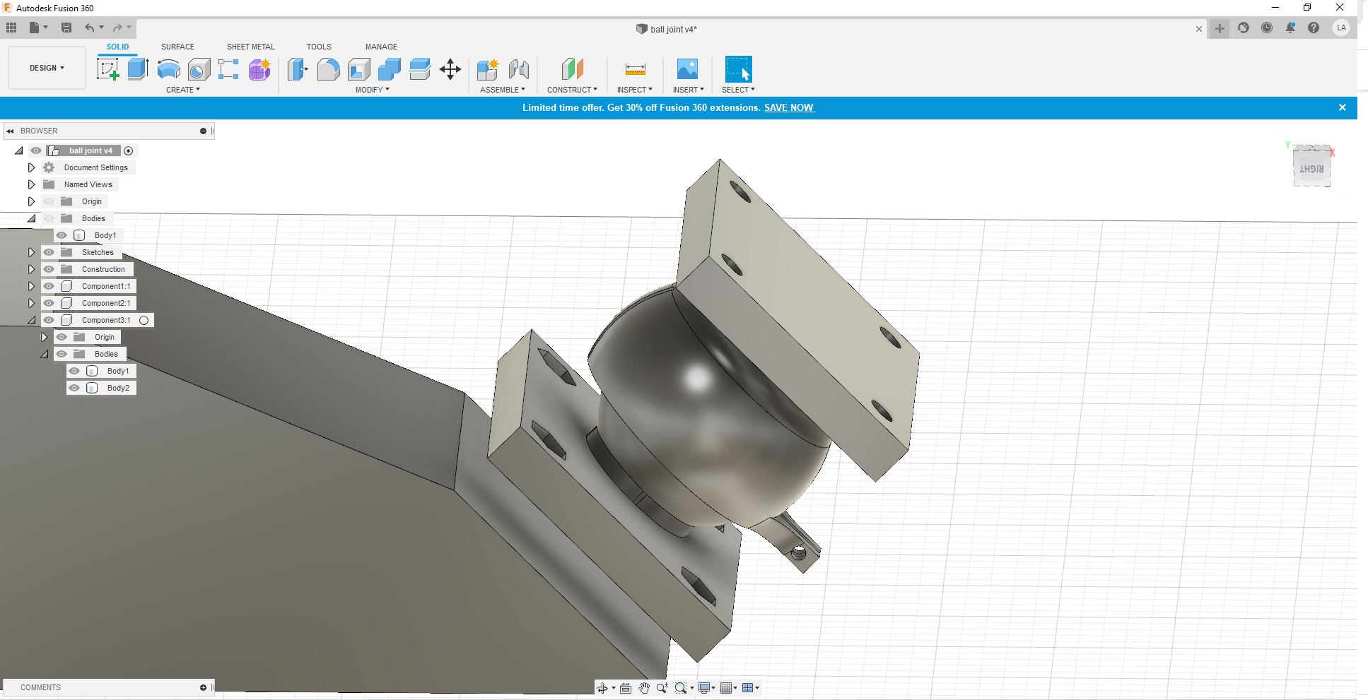
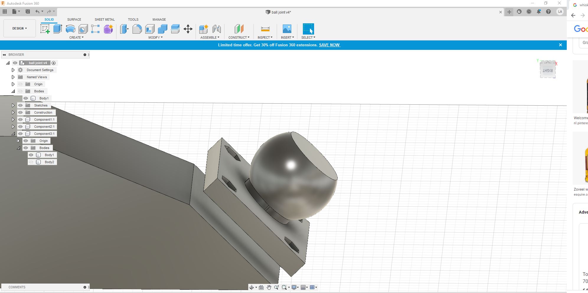
The second challenge is a maze that you have to solve. For this module i used 3D printing and lasercutting. The purpuse of this module is to solve the maze , inside the maze is a iron ball and by rotating the maze it is possible to solve the maze. I designed a ball joint in fusion360 so you can move the maze around and guide the ball inside the maze to the finish.
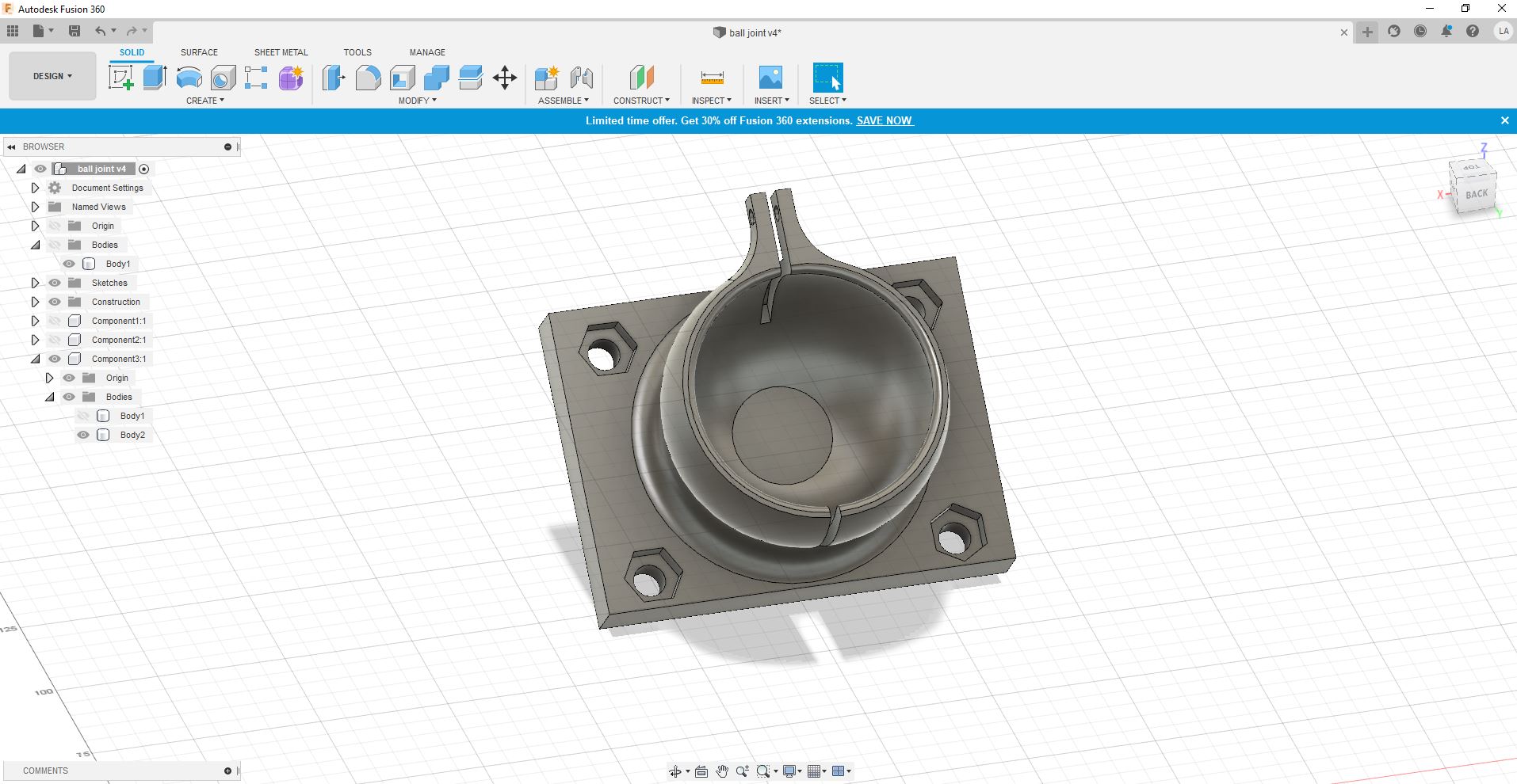
I printed this parts with the 3D printer (Ender3 pro) with the following settings
- layer height 0.15
- infill 40 %
- no support
When I tried to assemble the two pieces one broke.
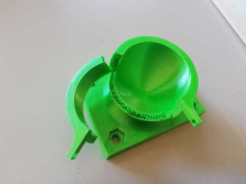
I printed the object again but with 60% infill. Before I assembeled the new parts I heated the hole piece with a heatgun. This proved succesfull. They clicked in eachother and cooled off perfecttely.
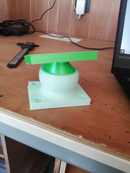
The next part is the maze. I made this part in inkscape and lasercuted it. I first made it with the cnc milling machine but it it was not good. Afterwards I decided to do it with the lasercutter. It was faster than milling it because the material is very thin.
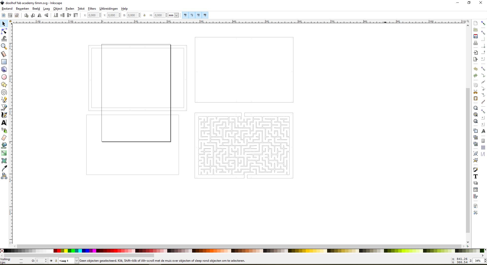
I made the main part out of 4 mm plywood and a sheet of PETG.
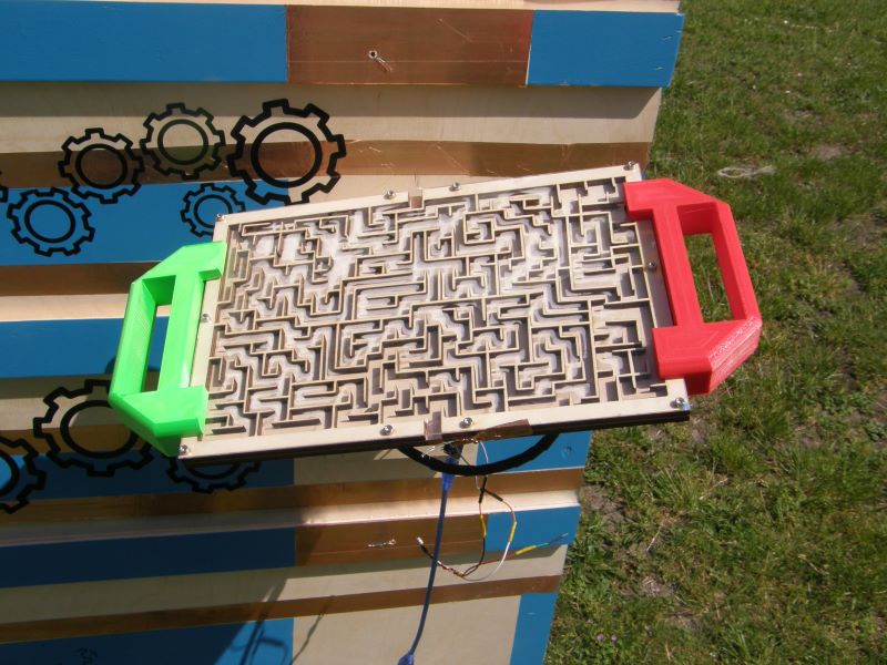
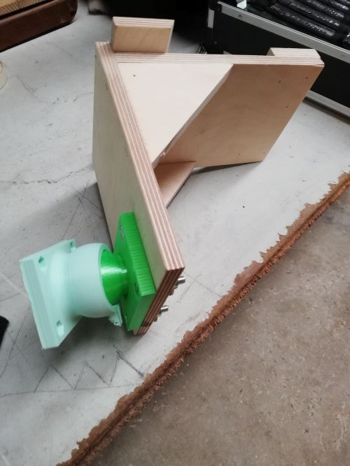
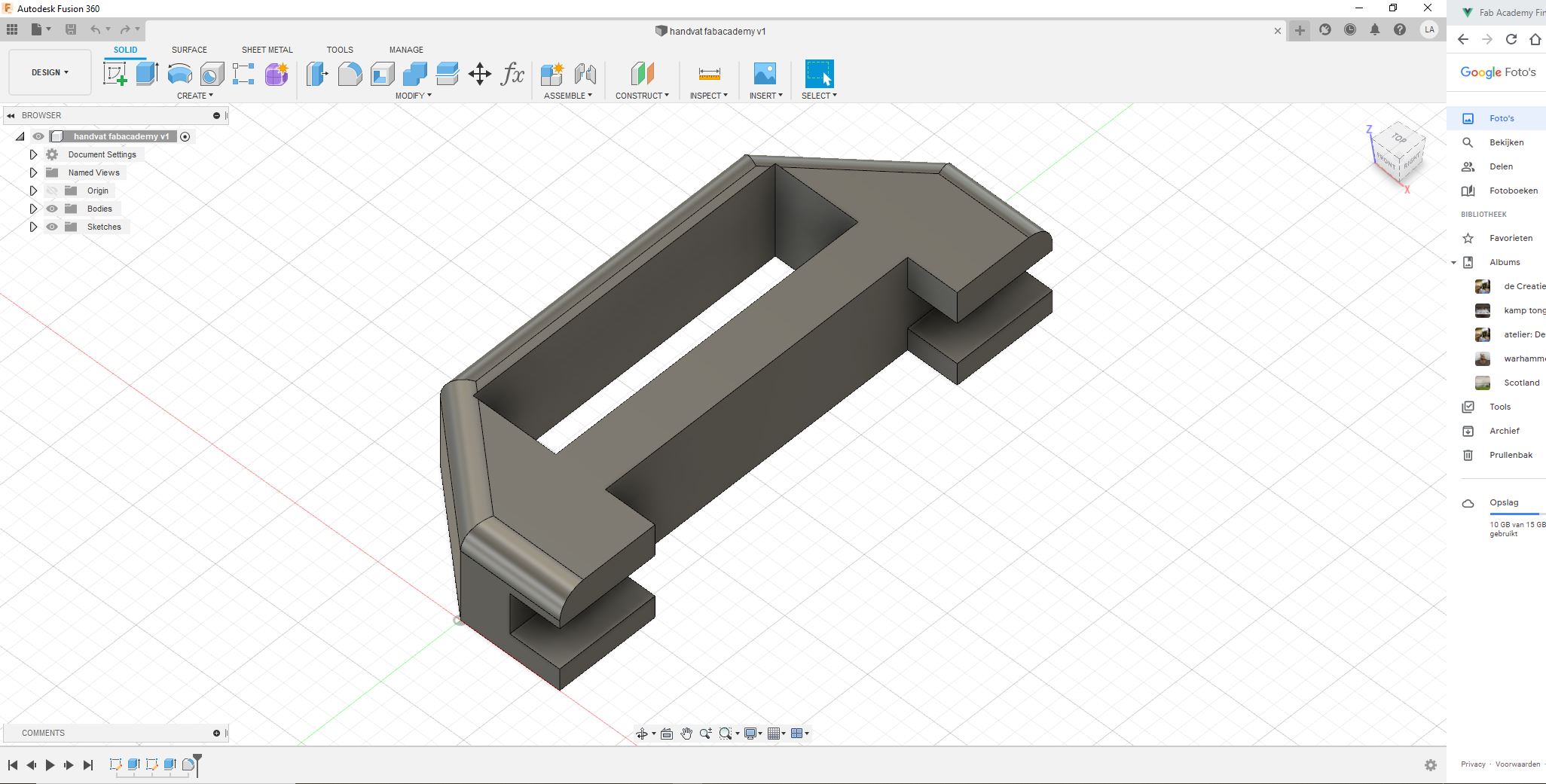
Now i assembeled this module. I noticed that it would be nicer to add some handles so i made 2 handels in fusion 360 and 3D printed them.
Now I added the electronic part, I soldered the parts and made the code.
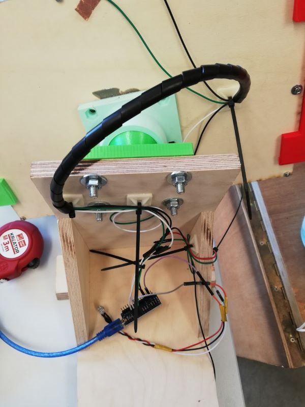
The code is the next part for this module. I also made it with blokkencode . This is the code:
int NeoPixel_2 = 6;
int Drukknop1 = 8;
int Drukknop1_2 = 7;
int DigOutput1 = 5;

#include <Adafruit_NeoPixel.h>
Adafruit_NeoPixel myNeo_NeoPixel_2 = Adafruit_NeoPixel(1, 6, NEO_GRB + NEO_KHZ800);
boolean Drukknop1_PRESSED = HIGH;

boolean Drukknop1_2_PRESSED = HIGH;

long Drukknop1buttonTimer = 0;
#define Drukknop1minShortPressTime 80
#define Drukknop1longPressTime 750
boolean Drukknop1buttonActive = false;
boolean Drukknop1longPressActive = false;
#define Drukknop1NOPRESS    0
#define Drukknop1SHORTPRESS 1
#define Drukknop1LONGPRESS  2
int Drukknop1PressType = Drukknop1NOPRESS;
long Drukknop1_2buttonTimer = 0;
#define Drukknop1_2minShortPressTime 80
#define Drukknop1_2longPressTime 750
boolean Drukknop1_2buttonActive = false;
boolean Drukknop1_2longPressActive = false;
#define Drukknop1_2NOPRESS    0
#define Drukknop1_2SHORTPRESS 1
#define Drukknop1_2LONGPRESS  2
int Drukknop1_2PressType = Drukknop1_2NOPRESS;

// Deze functie beschrijven...
void opstarten() {
  myNeo_NeoPixel_2.setPixelColor(1-1, myNeo_NeoPixel_2.Color(255,0,0));
  myNeo_NeoPixel_2.show();
  delay(1000);
  myNeo_NeoPixel_2.setPixelColor(1-1, myNeo_NeoPixel_2.Color(255,0,0));
  myNeo_NeoPixel_2.show();
  delay(1000);
  myNeo_NeoPixel_2.setPixelColor(1-1, myNeo_NeoPixel_2.Color(255,0,0));
  myNeo_NeoPixel_2.show();
}


void handleDrukknop1Press() {
  Drukknop1PressType = Drukknop1NOPRESS;
      if (digitalRead(Drukknop1) == Drukknop1_PRESSED) {
        if (Drukknop1buttonActive == false) {
          Drukknop1buttonActive = true;
          Drukknop1buttonTimer = millis();
        }
        if ((millis() - Drukknop1buttonTimer > Drukknop1longPressTime) && (Drukknop1longPressActive == false)) {
          Drukknop1longPressActive = true;
          Drukknop1PressType = Drukknop1LONGPRESS;
        }
      } else {
        if (Drukknop1buttonActive == true) {
          if (Drukknop1longPressActive == true) {
            Drukknop1longPressActive = false;
          } else {
            //avoid fast fluctuations to be identified as a click
            if (millis() - Drukknop1buttonTimer > Drukknop1minShortPressTime)
              Drukknop1PressType = Drukknop1SHORTPRESS;
          }
          Drukknop1buttonActive = false;
        }
      }
}


// Deze functie beschrijven...
void groen() {
  handleDrukknop1Press();

  if (Drukknop1PressType == Drukknop1SHORTPRESS) {
    //START STATEMENTS SHORT PRESS
    myNeo_NeoPixel_2.setPixelColor(1-1, myNeo_NeoPixel_2.Color(0,255,0));
    myNeo_NeoPixel_2.show();
    digitalWrite(5, HIGH);
    //END  STATEMENTS SHORT PRESS
  } else if (Drukknop1PressType == Drukknop1LONGPRESS) {
    //START STATEMENTS LONG PRESS
    //END  STATEMENTS LONG PRESS
  } else if (!Drukknop1longPressActive && digitalRead(Drukknop1) == Drukknop1_PRESSED) {
    //START STATEMENTS PRESS
    //END  STATEMENTS PRESS
  }

}


void handleDrukknop1_2Press() {
  Drukknop1_2PressType = Drukknop1_2NOPRESS;
      if (digitalRead(Drukknop1_2) == Drukknop1_2_PRESSED) {
        if (Drukknop1_2buttonActive == false) {
          Drukknop1_2buttonActive = true;
          Drukknop1_2buttonTimer = millis();
        }
        if ((millis() - Drukknop1_2buttonTimer > Drukknop1_2longPressTime) && (Drukknop1_2longPressActive == false)) {
          Drukknop1_2longPressActive = true;
          Drukknop1_2PressType = Drukknop1_2LONGPRESS;
        }
      } else {
        if (Drukknop1_2buttonActive == true) {
          if (Drukknop1_2longPressActive == true) {
            Drukknop1_2longPressActive = false;
          } else {
            //avoid fast fluctuations to be identified as a click
            if (millis() - Drukknop1_2buttonTimer > Drukknop1_2minShortPressTime)
              Drukknop1_2PressType = Drukknop1_2SHORTPRESS;
          }
          Drukknop1_2buttonActive = false;
        }
      }
}


// Deze functie beschrijven...
void rood() {
  handleDrukknop1_2Press();

  if (Drukknop1_2PressType == Drukknop1_2SHORTPRESS) {
    //START STATEMENTS SHORT PRESS
    myNeo_NeoPixel_2.setPixelColor(1-1, myNeo_NeoPixel_2.Color(255,0,0));
    myNeo_NeoPixel_2.show();
    digitalWrite(5, LOW);
    //END  STATEMENTS SHORT PRESS
  } else if (Drukknop1_2PressType == Drukknop1_2LONGPRESS) {
    //START STATEMENTS LONG PRESS
    //END  STATEMENTS LONG PRESS
  } else if (!Drukknop1_2longPressActive && digitalRead(Drukknop1_2) == Drukknop1_2_PRESSED) {
    //START STATEMENTS PRESS
    //END  STATEMENTS PRESS
  }

}


void setup() {
  myNeo_NeoPixel_2.begin();
  myNeo_NeoPixel_2.show();
  pinMode(Drukknop1, INPUT);
  pinMode(Drukknop1_2, INPUT);
  pinMode(DigOutput1, OUTPUT);
  pinMode(5, OUTPUT);

  opstarten();

}

void loop() {
  groen();
  rood();

}
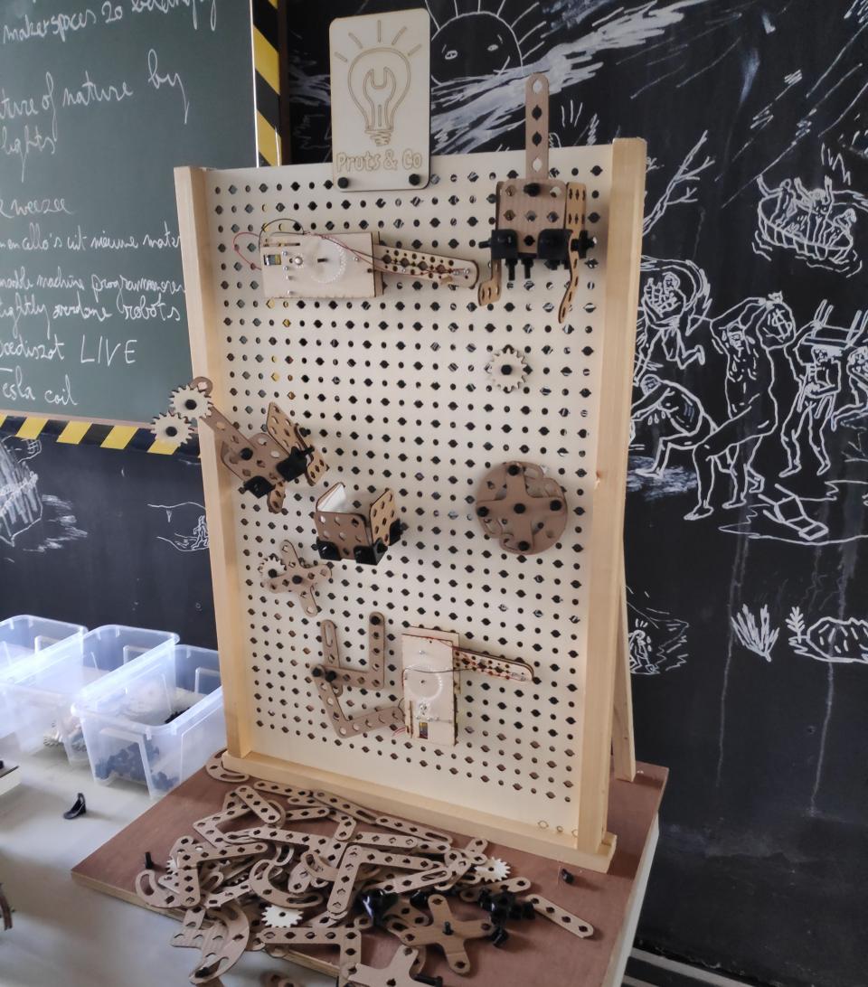
assemble everything and monyshots
Now that some modules are ready i put everything together.
The 2 Modules I have made work, I wished I had time to make some more before the presentation, it is something that I will work on some more and hopefully during the summer in one of our makercamps in the lab. I have a couple of ideas that i want to make:
- including a timer and scoreboard
- a module linked to a app on the smartphone with a quiz about science and technology.
- elektrogame
- making the board with the milling machine
eletronic design and production
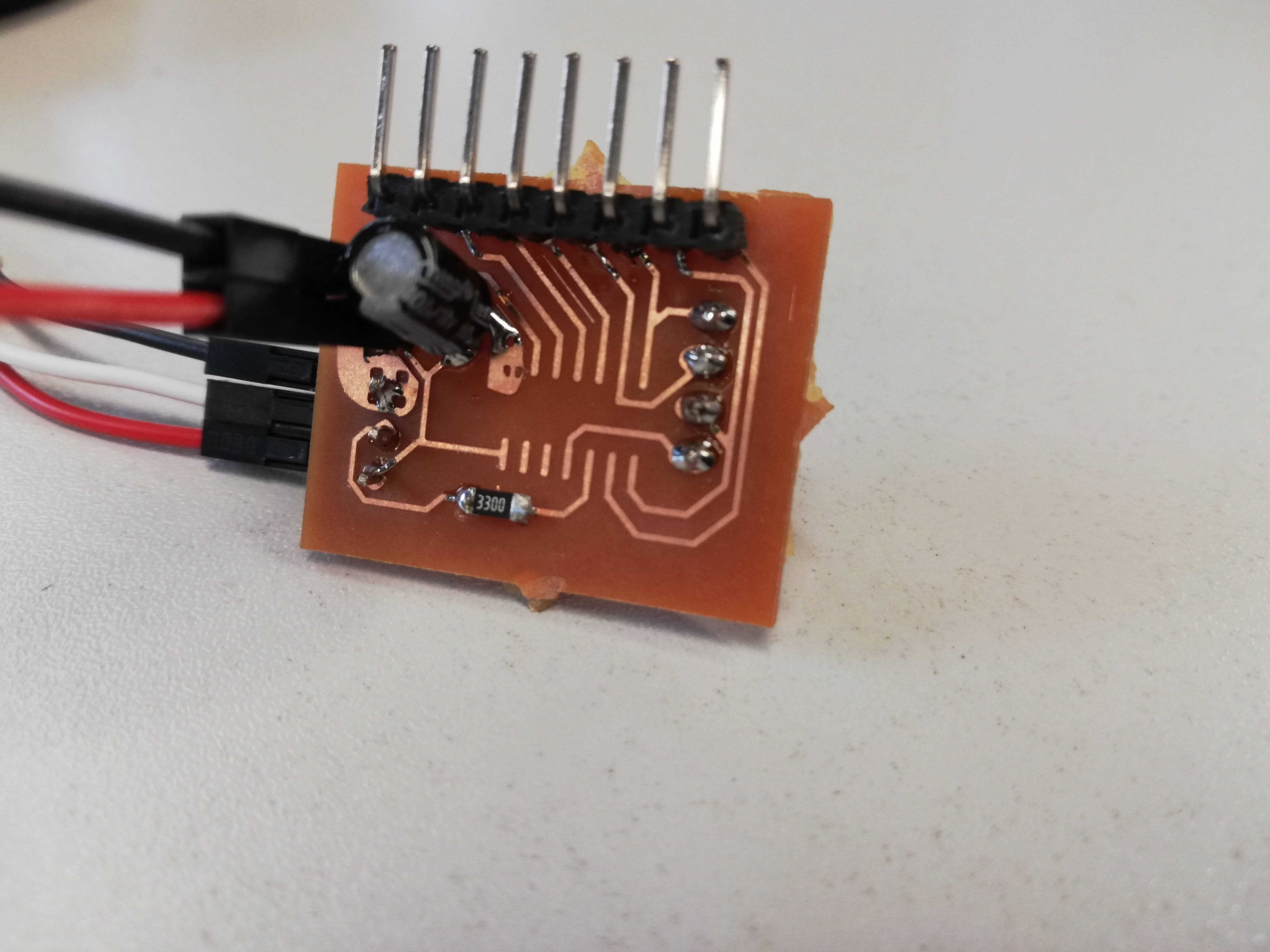
The last big part of the final project is designing and making a PCB. I decide not to make a PCB as main component, but i decided to make a module with PCB of my own. the main reason for this is that i want to implement the project with children and that they can make their own module and i know that making pcb ‘s is too hard to do with children. it is impotant to show them that it excists and that you can make them your own. but the challenge for them is to make a module of their own.
The module I have added is a riddle about coulour they have to guess the right coulour and hold it in front of the sensor. When it is the right colour the board will dedect it and give a signal to the master.
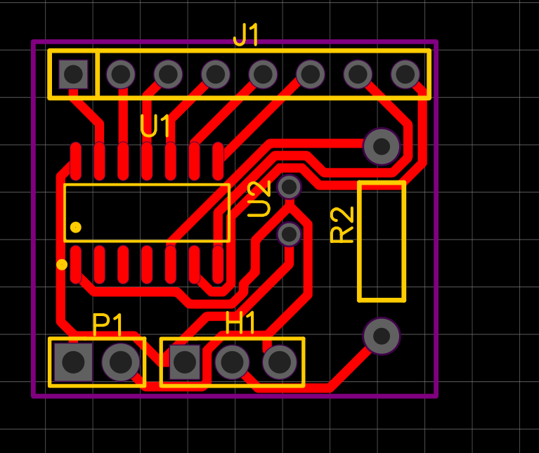
I want to include the colour sensor in the wall The idea is that you have to download the app on you phone and change the colour of the RGB Led when is the correct colour the sensor will detect it and give a high signal to the wall. I have made a board for this in week 11 And remade it in week12 with the integraded neopixel.
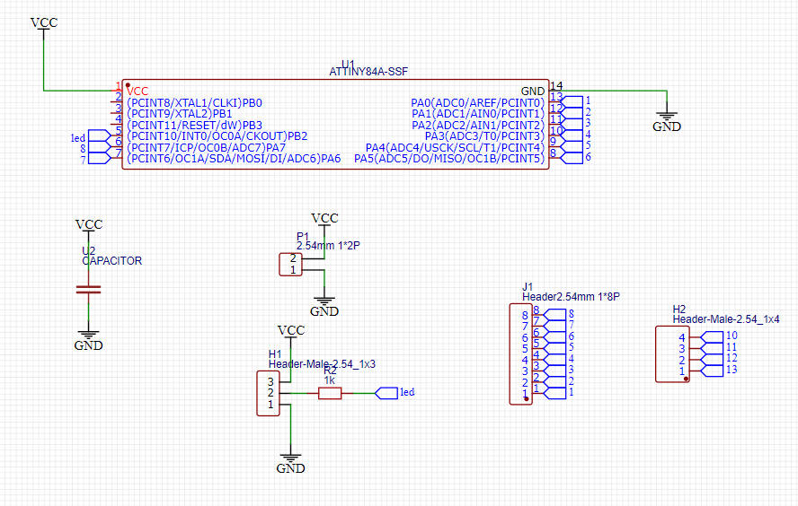
After testing with the arduino it was time to replace the arduino with its own pcb. After some consultation with some colleagues in the lab, I used easy EDA to draw this. As a microcontroller I used an ATtiny84 because it has enough programmable pins. This replaces the ardiuno. It needs 8 pins that gets a high or low signal and changes the pixel on the neopix accordingly.
Here i found the datasheet for the ATtiny84.
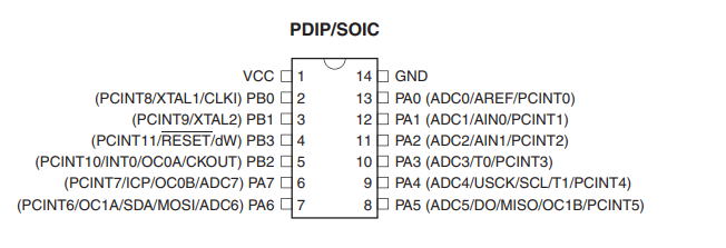
-
Port B is a 4-bit bi-directional I/O port with internal pull-up resistors (selected for each bit). The Port B output buffers have symmetrical drive characteristics with both high sink and source capability except PB3 which has the RESET capability. To use pin PB3 as an I/O pin, instead of RESET pin, program (‘0’) RSTDISBL fuse. As inputs, Port B pins that are externally pulled low will source current if the pull-up resistors are activated. The Port B pins are tri-stated when a reset condition becomes active, even if the clock is not running.
-
Reset input. A low level on this pin for longer than the minimum pulse length will generate a reset, even if the clock is not running.
-
Port A is a 8-bit bi-directional I/O port with internal pull-up resistors (selected for each bit). The Port A output buffers have symmetrical drive characteristics with both high sink and source capability. As inputs, Port A pins that are externally pulled low will source current if the pull-up resistors are activated. The Port A pins are tri-stated when a reset condition becomes active, even if the clock is not running.
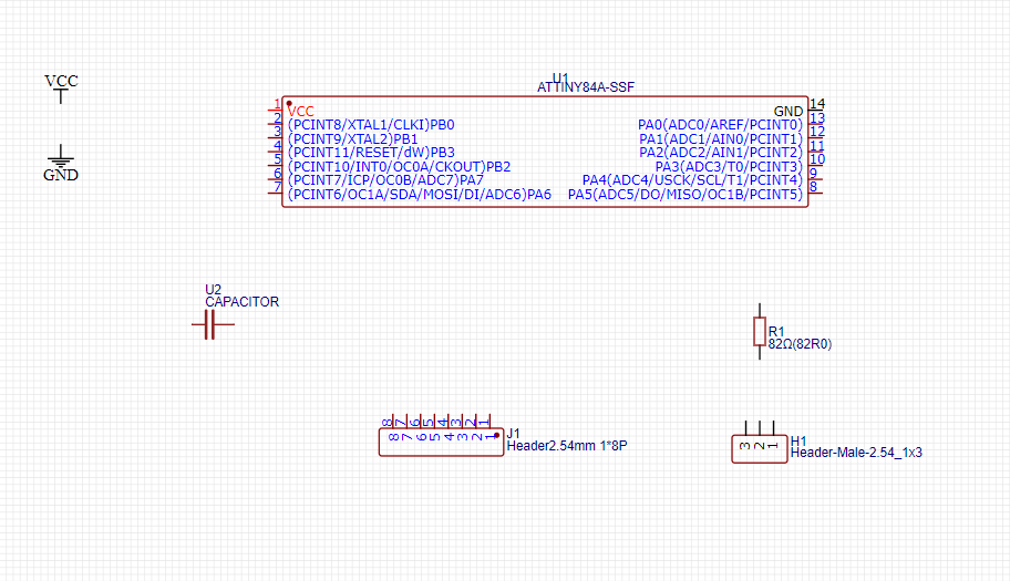
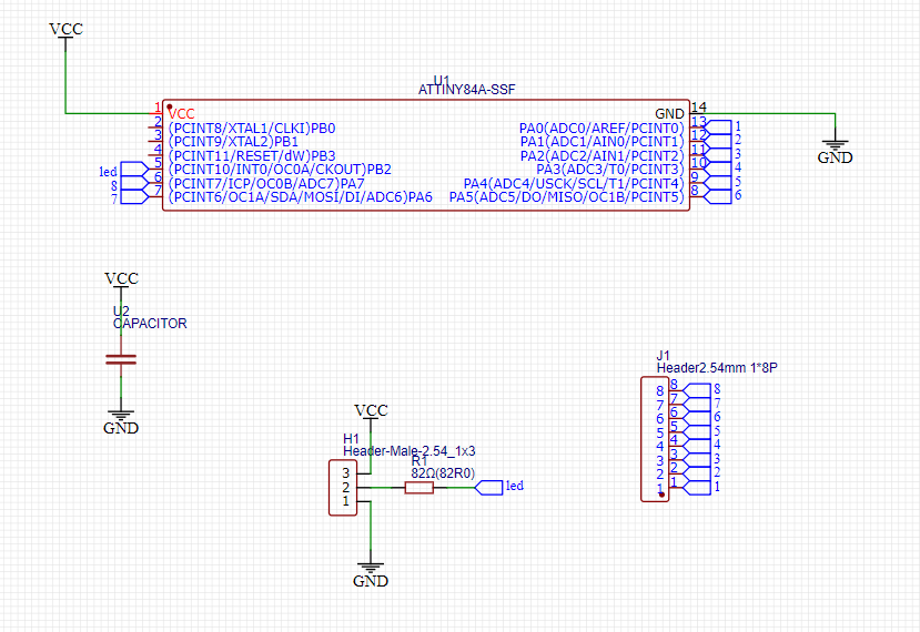
After some feedback fom my colleages i worked wit easyEDA. With this programe i had less problems finding the right footprints than in KICAD. I made a new board:
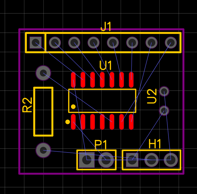
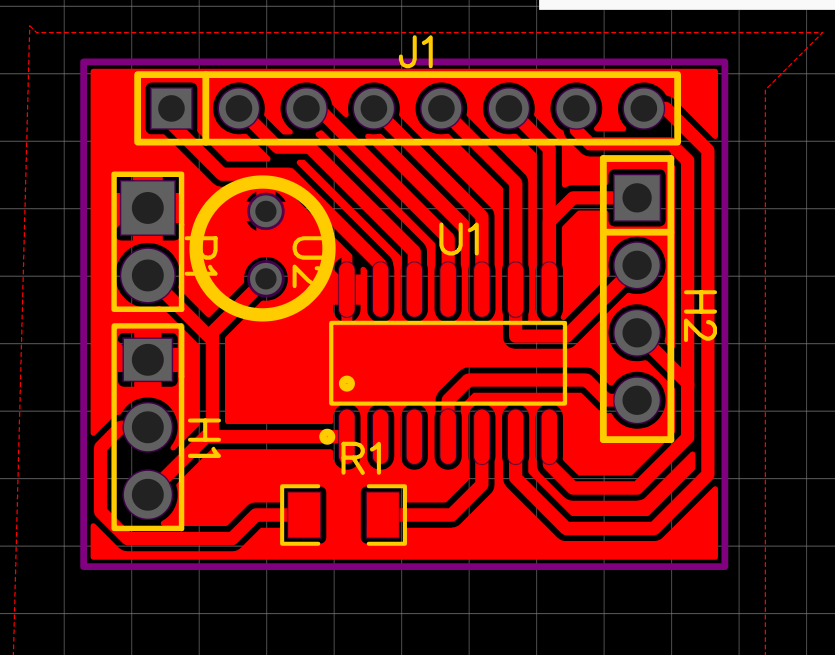
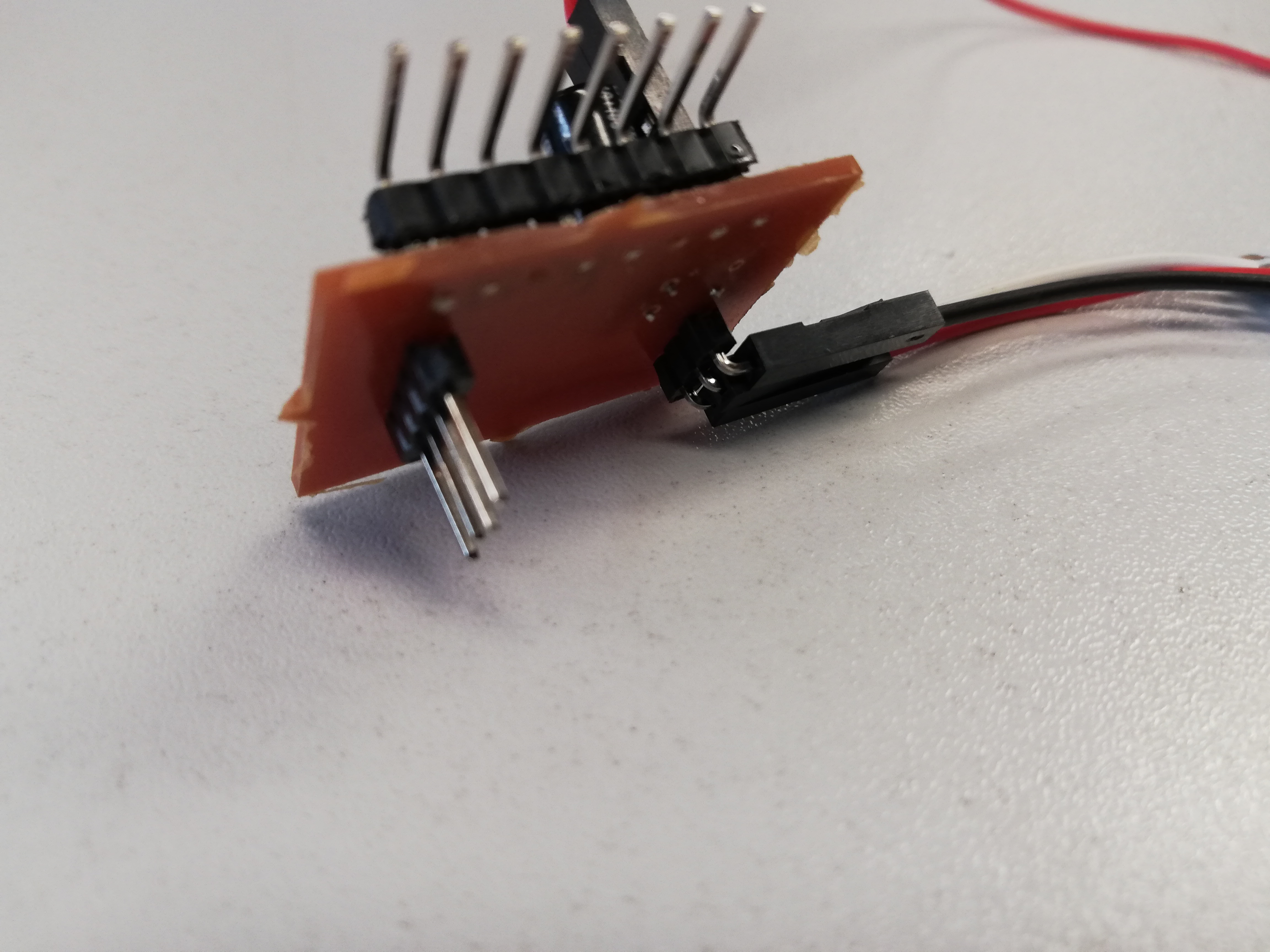
I started milling the same way i did in week 5
intelectual property.
I want my project to be open source with creative commons. Everything we make here in the lab with the creative STEM is free to use if they mension our name. Everybody can Get all the plans. i want to revere to the assigment of week 18. i explane everything over there.
Thank you
As last I want to thank everybody in mine enviroment for the help and motivation to get trough this course.
First of all I want to give a special thanks to Dr.Maria-Cristina Ciocci and Dr.Benny Malengier from Ingegno fab lab to give me the opportiunity to enter this programme and give a lot of advice during the classes. I want to thank my colleagues from the creative STEM to listen to my projects and help brainstorming for the assignments and final project.
At last I want to thank my instructor Hadil Habashneh to guide through the course and help with all the problems that came by.
downloads
- logo
- reset the wall plate
- stickers gears
- titel
- code master
- holder neopixel
- code maze
- code nerve game
- ball joint
- ball joint 2
- handle
- code nerve game