11. Input devices
I have chosen to work with a color sensor. The sensor I used is TCS230 TCS3200 Color and an ATtiny
I used the following tutorial as guideline for making my board.
TCS230 color sensor
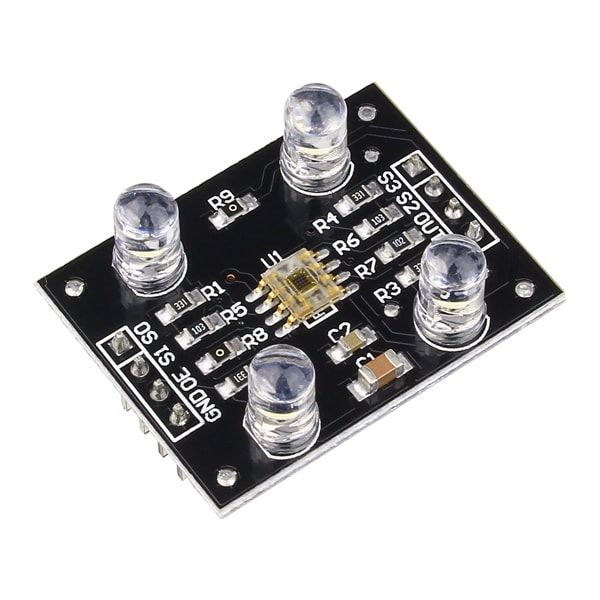
The TCS3200 color sensor – shown in the figure above – uses a TAOS TCS3200 RGB sensor chip to detect color. It also contains four white LEDs that light up the object in front of it.
specifications
- Power: 2.7V to 5.5V
- Size: 28.4 x 28.4mm (1.12 x 1.12″)
- Interface: digital TTL
- High-resolution conversion of light intensity to frequency
- Programmable color and full-scale output frequency
- Communicates directly to microcontroller
TAOS TCS3200 RGB sensorchip
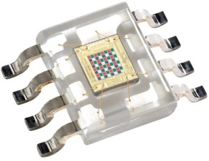
The TCS3200 has an array of photodiodes with 4 different filters. A photodiode is simply a semiconductor device that converts light into current. The sensor has:
- 16 photodiodes with red filter – sensitive to red wavelength
- 16 photodiodes with green filter – sensitive to green wavelength
- 16 photodiodes with blue filter – sensitive to blue wavelength
- 16 photodiodes without filter
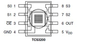
pinout of the sensor
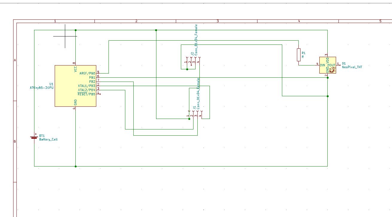
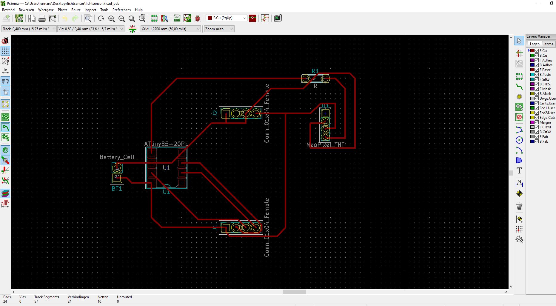
Testing everything on a breadboard
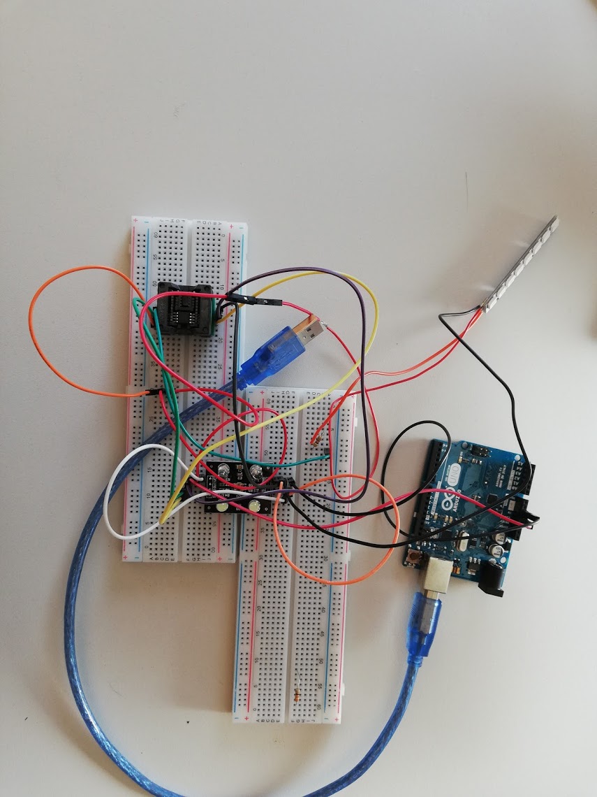
Before making the board I started with making the circuit on a breadboard. When it was working I started in KiCAD. I still find it a difficult proces to make my own boards. I lose a lot of time designing them, the milling part works very well and i understand that complettely but designing them and knowing which components i have to use is still a difficult task that takes a lot of time. That being said I desiged it and milled in with the machine. I used KiCAD for the design and drawing.
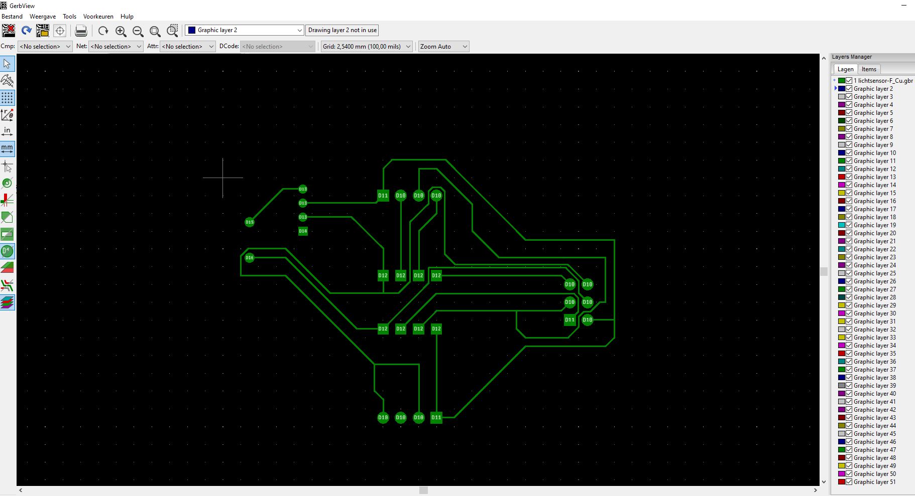
milling the board.
I used the same setting as in week5
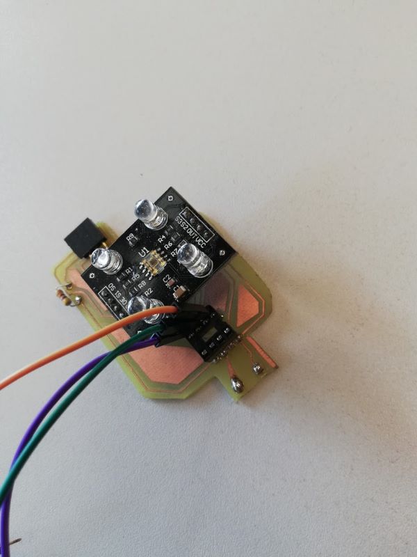
programming the board
I used this test code: This code mesures the colour of the object you hold in front of it. It is not very stable. it depends a lot on how much light there is in the room when you measure it.
/*     Arduino Color Sensing Tutorial
 *
 *  by Dejan Nedelkovski, www.HowToMechatronics.com
 *
 */

#define S0 4
#define S1 5
#define S2 6
#define S3 7
#define sensorOut 8
int frequency = 0;
void setup() {
  pinMode(S0, OUTPUT);
  pinMode(S1, OUTPUT);
  pinMode(S2, OUTPUT);
  pinMode(S3, OUTPUT);
  pinMode(sensorOut, INPUT);

  // Setting frequency-scaling to 100%
  digitalWrite(S0,HIGH);
  digitalWrite(S1,HIGH);
  // Setting frequency-scaling to 20%
  //digitalWrite(S0,HIGH);
  //digitalWrite(S1,LOW);
  // Setting frequency-scaling to 2%
  //digitalWrite(S0,LOW);
  //digitalWrite(S1,HIGH);

  Serial.begin(9600);
}
void loop() {
  // Setting red filtered photodiodes to be read
  digitalWrite(S2,LOW);
  digitalWrite(S3,LOW);
  // Reading the output frequency
  frequency = pulseIn(sensorOut, digitalRead(sensorOut) == HIGH ? LOW : HIGH);
  //Remaping the value of the frequency to the RGB Model of 0 to 255
  //frequency = map(frequency, 25,72,255,0);
  // Printing the value on the serial monitor
  Serial.print("R= ");//printing name
  Serial.print(frequency);//printing RED color frequency
  Serial.print("  ");
  delay(20);
  // Setting Green filtered photodiodes to be read
  digitalWrite(S2,HIGH);
  digitalWrite(S3,HIGH);
  // Reading the output frequency
  frequency = pulseIn(sensorOut, digitalRead(sensorOut) == HIGH ? LOW : HIGH);
  //Remaping the value of the frequency to the RGB Model of 0 to 255
  //frequency = map(frequency, 30,90,255,0);
  // Printing the value on the serial monitor
  Serial.print("G= ");//printing name
  Serial.print(frequency);//printing RED color frequency
  Serial.print("  ");
  delay(20);
  // Setting Blue filtered photodiodes to be read
  digitalWrite(S2,LOW);
  digitalWrite(S3,HIGH);
  // Reading the output frequency
  frequency = pulseIn(sensorOut, digitalRead(sensorOut) == HIGH ? LOW : HIGH);
  //Remaping the value of the frequency to the RGB Model of 0 to 255
  //frequency = map(frequency, 25,70,255,0);
  // Printing the value on the serial monitor
  Serial.print("B= ");//printing name
  Serial.print(frequency);//printing RED color frequency
  Serial.print("  ");
  delay(20);
  // Setting Clear filtered photodiodes to be read
  digitalWrite(S2,HIGH);
  digitalWrite(S3,LOW);
  // Reading the output frequency
  frequency = pulseIn(sensorOut, digitalRead(sensorOut) == HIGH ? LOW : HIGH);
  //Remaping the value of the frequency to the RGB Model of 0 to 255
  //frequency = map(frequency, 25,70,255,0);
  // Printing the value on the serial monitor
  Serial.print("Clear= ");//printing name
  Serial.print(frequency);//printing RED color frequency
  Serial.println("  ");
  delay(1000);
  ```

   ```
  #define attiny85 false

// set the pin values - Module pins wiring
short s0 = 4;
short s1 = 5;
short s2 = 6;
short s3 = 7;
short out = 8;
short NeoPixel = 10;
short s2_attiny = 2;
short s3_attiny = 3;
short out_attiny = 4;
short NeoPixel_attiny = 0;

int Red=0, Blue=0, Green=0, BW_val=0;

int i;

#include <Adafruit_NeoPixel.h>
Adafruit_NeoPixel myNeo_NeoPixel = Adafruit_NeoPixel(8, NeoPixel, NEO_GRB + NEO_KHZ800);

void setup()
{
  if (attiny85) {
    s2 = s2_attiny;
    s3 = s3_attiny;
    out = out_attiny;
    NeoPixel = NeoPixel_attiny;
  }
  myNeo_NeoPixel = Adafruit_NeoPixel(8, NeoPixel, NEO_GRB + NEO_KHZ800);
  if (!attiny85) {
    // these are hard wired on attiny85
    pinMode(s0,OUTPUT);
    pinMode(s1,OUTPUT);
  }
  pinMode(s2,OUTPUT);
  pinMode(s3,OUTPUT);
  pinMode(out,INPUT);

  if (!attiny85) {
    Serial.begin(9600);   //intialize the serial monitor baud rate
    // output freq
    digitalWrite(s0,HIGH); //Putting S0/S1 on HIGH/HIGH levels means the output frequency scalling is at 100% (recommended)
    digitalWrite(s1,LOW); //LOW/LOW is off HIGH/LOW is 20% and LOW/HIGH is  2%
  }

  myNeo_NeoPixel.begin();
  myNeo_NeoPixel.show();
}

void loop()
{
  GetColors();                                    //Execute the GetColors function

  if (!attiny85) {
    Serial.print("measuring colour RGB (");
    Serial.print(Red);
    Serial.print(", ");
    Serial.print(Green);
    Serial.print(", ");
    Serial.print(Blue);
    Serial.print(") - ");
    Serial.println(BW_val);
  }

  //remap BW_val to 0 to 100, with 0 dark, 100 full light
  BW_val = map(BW_val,9,110,100,0);
  //constrain BW_val value to brightness in %;
  BW_val = (BW_val < 0 ? 0 : ( BW_val > 100 ? 100 : BW_val));

  //remap RGB to BW_val 100 values
  Red = (float) Red /BW_val * 100.0;
  Green = (float) Green /BW_val * 100.0;
  Blue = (float) Blue /BW_val * 100.0;

  if (!attiny85) {
    Serial.print("Remapped brightness colour RGB (");
    Serial.print(Red);
    Serial.print(", ");
    Serial.print(Green);
    Serial.print(", ");
    Serial.print(Blue);
    Serial.print(") - ");
    Serial.println(BW_val);
  }

  //remap to RGB values
  Red = map(Red,15,55,255,0);
  Green = map(Green,30,105,255,0);
  Blue = map(Blue,13,45,255,0);

  //constrain RGB values;
  Red = (Red < 0 ? 0 : ( Red > 255 ? 255 : Red));
  Green = (Green < 0 ? 0 : ( Green > 255 ? 255 : Green));
  Blue = (Blue < 0 ? 0 : ( Blue > 255 ? 255 : Blue));

  if (!attiny85) {
    Serial.print("Computed RGB out (");
    Serial.print(Red);
    Serial.print(", ");
    Serial.print(Green);
    Serial.print(", ");
    Serial.print(Blue);
    Serial.print(") - ");
    Serial.println(BW_val);
  }

  //show on neopixels, dim if dark and not clear to see!
  if (BW_val > 40) {
    for (i = 1; i <= 8; i++) {
      myNeo_NeoPixel.setPixelColor(i-1, myNeo_NeoPixel.Color(Red,Green,Blue));
      myNeo_NeoPixel.show();
    }
  } else {
    for (i = 1; i <= 8; i++) {
      myNeo_NeoPixel.setPixelColor(i-1, myNeo_NeoPixel.Color(Red*BW_val/100,Green*BW_val/100,Blue*BW_val/100));
      myNeo_NeoPixel.show();
      }
  }

  delay(1000);
}

void GetColors()
{
  digitalWrite(s2, LOW);                                           //S2/S3 levels define which set of photodiodes we are using LOW/LOW is for RED LOW/HIGH is for Blue and HIGH/HIGH is for green
  digitalWrite(s3, LOW);
  Red = pulseIn(out, digitalRead(out) == HIGH ? LOW : HIGH);       //here we wait until "out" go LOW, we start measuring the duration and stops when "out" is HIGH again, if you have trouble with this expression check the bottom of the code
  delay(20);
  digitalWrite(s3, HIGH);                                         //Here we select the other color (set of photodiodes) and measure the other colors value using the same techinque
  Blue = pulseIn(out, digitalRead(out) == HIGH ? LOW : HIGH);
  delay(20);
  digitalWrite(s2, HIGH);
  Green = pulseIn(out, digitalRead(out) == HIGH ? LOW : HIGH);
  delay(20);
  digitalWrite(s3, LOW);
  BW_val = pulseIn(out, digitalRead(out) == HIGH ? LOW : HIGH);
}

//Here's an example how to understand that expression above,
//""digitalRead(out) == HIGH ? LOW : HIGH"" this whole expression is either HIGH or LOW as pulseIn function requires a HIGH/LOW value on the second argument

//led_Status = led_Status == HIGH ? LOW : HIGH;
//
//if(led_Status == HIGH)
//{
//led_Status =LOW;
//}
//else
//{
//led_Status = HIGH;
//}
Wat is happening
The sensor will detect the colour and give a RGB value.