14. Networking and communications
assiggnment and components.
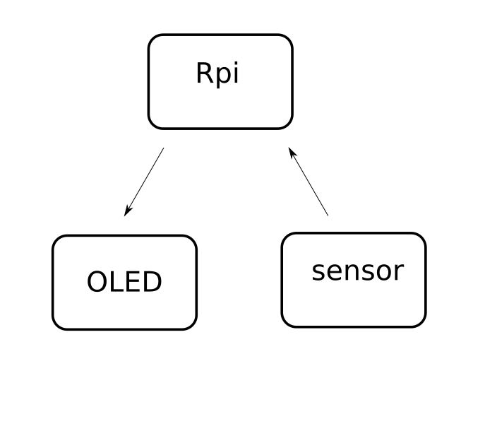
The assignment I want to make is a color sensor that forwards the RGB value and displays it on an OLED. For this I use two esp8266 mounted on a wemos board. Each Wemos connects to a rasberry pi
The components I used are:
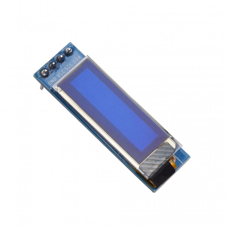
OLED
OLED This is on the reciever wemons it is a little screen that will display the RGB value.
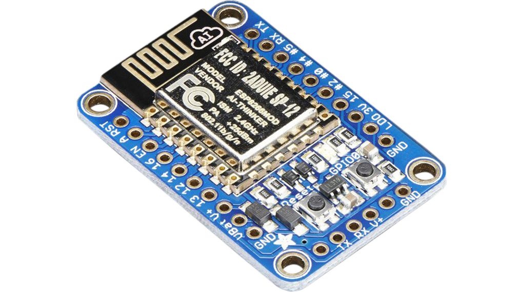
wemos with esp8266
These two board will communicate with eachother
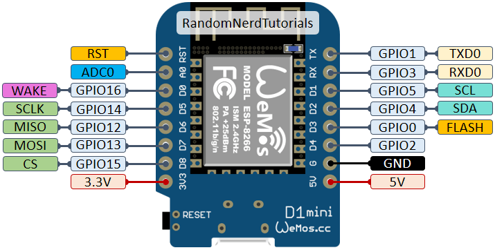
pinout:
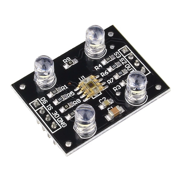
colour sensor tcs3200
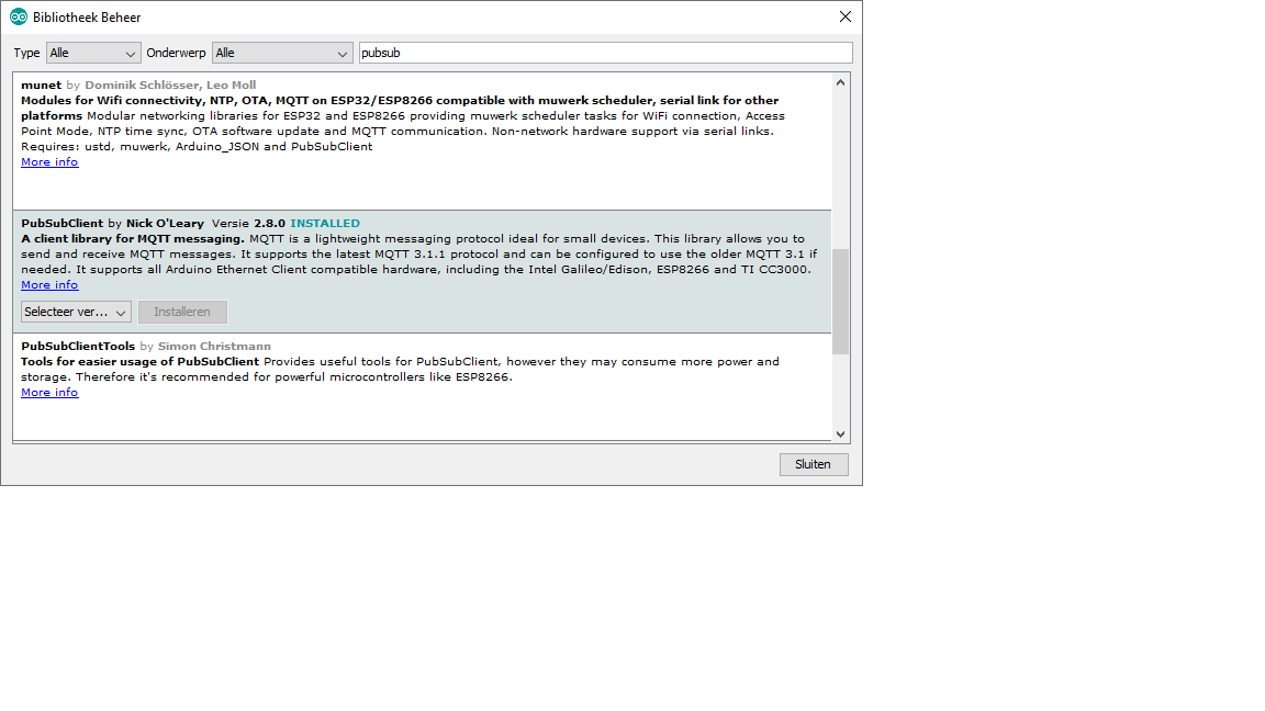
installing the libraries in ardiuno IDE
1) go to preferences
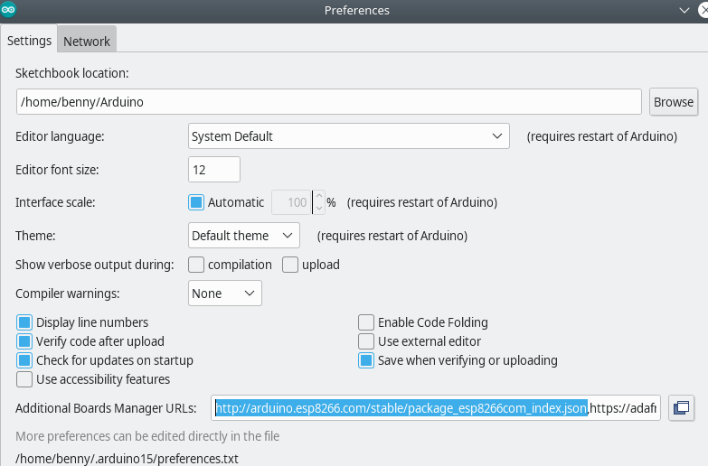
copy this link and past it in additional boards manager URLs . Click on ok.
2) Instaling the library
Go to Tools–> board –> board manager
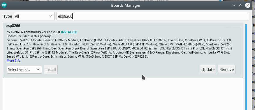
Click on instal library
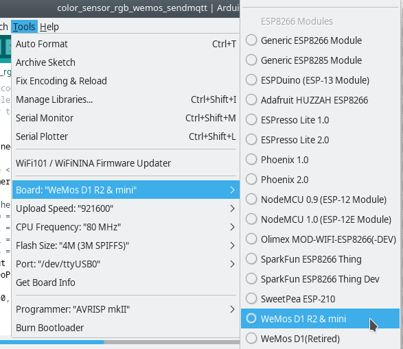
Now go to tools and choose for the board wemosD1 R2& mini
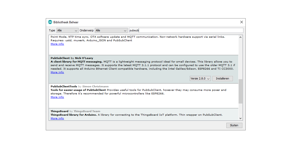
MQTT
The Message Queuing Telemetry Transport (MQTT) is a lightweight, publish-subscribe network protocol that transports messages between devices. The protocol usually runs over TCP/IP; however, any network protocol that provides ordered, lossless, bi-directional connections can support MQTT. It is designed for connections with remote locations where a “small code footprint” is required or the network bandwidth is limited. The protocol is an open OASIS standard and an ISO recommendation (ISO/IEC 20922).
Installing MQTT on rasberry pi I followed the following instruction from my colleage at the lab.
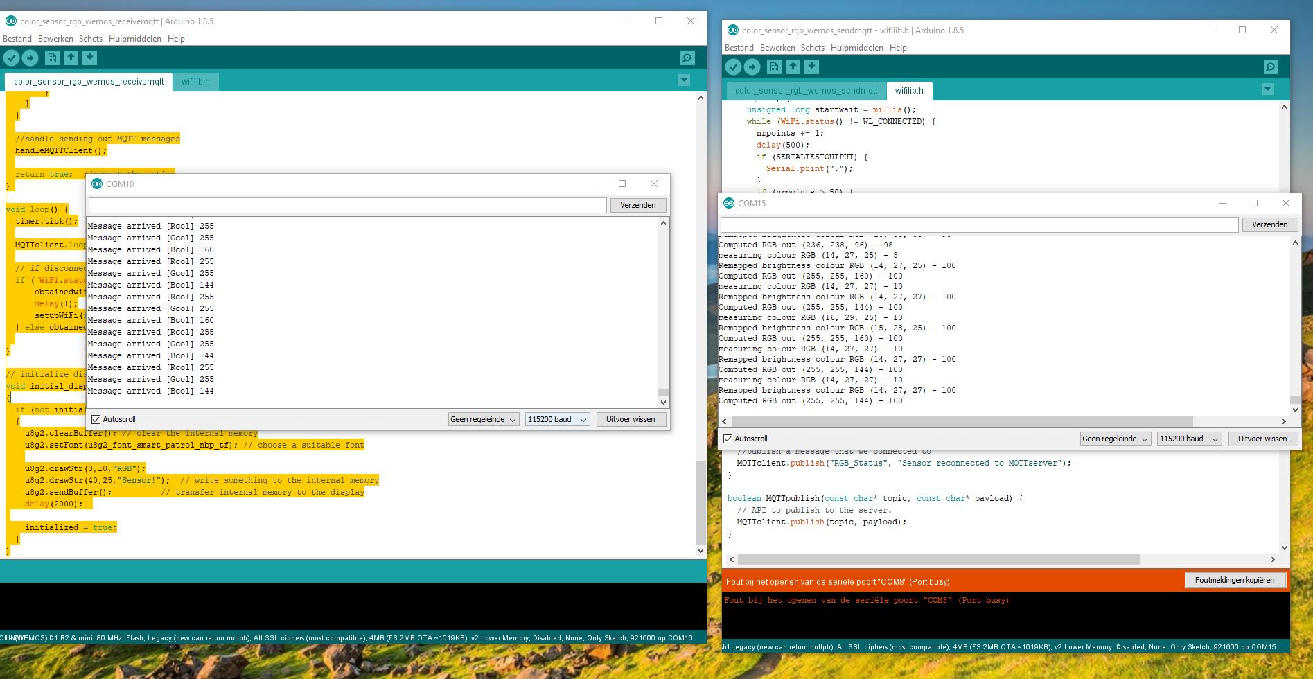
sender
The sender with the coloursensor has the following code:
/* This code works with GY-31 TCS3200 TCS230 color sensor module
 * It select a photodiode set and read its value (Red Set/Blue set/Green set) and reproduce the color on the RGB LED
 * Refer to www.surtrtech.com for more details
 */

#define neopixels false

/*  START USER SETTABLE OPTIONS */
/*
Variables:
 * SERIALTESTOUTPUT : show debug info in serial at 115200
 * SHOWonU8g2: show info on the OLED display
 * connectedelectrodes: how many electrodes are used of the MPR121 ?
 * Long sleep detection: with fixed cutoff value inbed_cap: set it correctly ...
*/

const bool SERIALTESTOUTPUT = true;
const bool WAITFORNETWORK = true;
#define SERIALSPEED 115200

bool use_static_IP = false;         //use a static IP address
uint8_t static_IP[4] = {192, 168, 1, 42};
uint8_t static_gateway_IP[4] = {192, 168, 1, 1};// if you want to use static IP make sure you know what the gateway IP is, here 192.168.1.1

// wifi data
// write here your wifi credentials
const char* password = "**********"; // and password
const char* ssid = "***********";   // insert your own ssid

//mqtt server/broker
//const char* mqtt_server = "broker.mqtt-dashboard.com";
const char* mqtt_server = "***.***.**.***";  //eth0 address of the raspberry pi

/*  END USER SETTABLE OPTIONS */

#include <arduino-timer.h>
auto timer = timer_create_default();

// set the pin values - Module pins wiring
short s0 = D0;
short s1 = D5;
short s2 = D6;
short s3 = D7;
short out = D8;
short NeoPixel = D3;

int Red=0, Blue=0, Green=0, BW_val=0;

int i;

#include <Adafruit_NeoPixel.h>
Adafruit_NeoPixel myNeo_NeoPixel = Adafruit_NeoPixel(8, NeoPixel, NEO_GRB + NEO_KHZ800);

// our own wifi and timing lib
#include "wifilib.h"

void setup()
{
  if (neopixels) {
    myNeo_NeoPixel = Adafruit_NeoPixel(8, NeoPixel, NEO_GRB + NEO_KHZ800);
  }
  pinMode(s0,OUTPUT);
  pinMode(s1,OUTPUT);
  pinMode(s2,OUTPUT);
  pinMode(s3,OUTPUT);
  pinMode(out,INPUT);

  Serial.begin(SERIALSPEED);   //intialize the serial monitor baud rate
  // output freq
  digitalWrite(s0,HIGH); //Putting S0/S1 on HIGH/HIGH levels means the output frequency scalling is at 100% (recommended)
  digitalWrite(s1,LOW); //LOW/LOW is off HIGH/LOW is 20% and LOW/HIGH is  2%

  if (neopixels) {
    myNeo_NeoPixel.begin();
    myNeo_NeoPixel.show();
  }

  while (WiFi.status() != WL_CONNECTED && WAITFORNETWORK) {
   setupWiFi(true); // Connect to local Wifi
  }
  if (! WAITFORNETWORK) {
    if ( WiFi.status() != WL_CONNECTED) {
        obtainedwifi = false;
        delay(1);
        setupWiFi(false);
    } else obtainedwifi = true;
  }

  // mqtt client start
  // Here we subscribe to MQTT topic if wanted
  setupMQTTClient();

  if (SERIALTESTOUTPUT) {
    Serial.println("");
    Serial.print("Connected to WiFi at ");
  }
  ip = WiFi.localIP();
  if (SERIALTESTOUTPUT) {
    Serial.print(ip);
    Serial.println("");
    Serial.print("Wifi end of IP: ");
    Serial.print(ip[3]);
    Serial.println("");
  }
  obtainedwifi = true;

  timer.every(1000, do_action); //call do_action every 1000 ms
}

bool do_action(void *argument)
{
  GetColors();                                    //Execute the GetColors function

  if (SERIALTESTOUTPUT) {
    Serial.print("measuring colour RGB (");
    Serial.print(Red);
    Serial.print(", ");
    Serial.print(Green);
    Serial.print(", ");
    Serial.print(Blue);
    Serial.print(") - ");
    Serial.println(BW_val);
  }

  //remap BW_val to 0 to 100, with 0 dark, 100 full light
  BW_val = map(BW_val,9,110,100,0);
  //constrain BW_val value to brightness in %;
  BW_val = (BW_val < 0 ? 0 : ( BW_val > 100 ? 100 : BW_val));

  //remap RGB to BW_val 100 values
  Red = (float) Red /BW_val * 100.0;
  Green = (float) Green /BW_val * 100.0;
  Blue = (float) Blue /BW_val * 100.0;

  if (SERIALTESTOUTPUT) {
    Serial.print("Remapped brightness colour RGB (");
    Serial.print(Red);
    Serial.print(", ");
    Serial.print(Green);
    Serial.print(", ");
    Serial.print(Blue);
    Serial.print(") - ");
    Serial.println(BW_val);
  }

  //remap to RGB values
  Red = map(Red,15,55,255,0);
  Green = map(Green,30,105,255,0);
  Blue = map(Blue,13,45,255,0);

  //constrain RGB values;
  Red = (Red < 0 ? 0 : ( Red > 255 ? 255 : Red));
  Green = (Green < 0 ? 0 : ( Green > 255 ? 255 : Green));
  Blue = (Blue < 0 ? 0 : ( Blue > 255 ? 255 : Blue));

  if (SERIALTESTOUTPUT) {
    Serial.print("Computed RGB out (");
    Serial.print(Red);
    Serial.print(", ");
    Serial.print(Green);
    Serial.print(", ");
    Serial.print(Blue);
    Serial.print(") - ");
    Serial.println(BW_val);
  }

  if (neopixels) {
    //show on neopixels, dim if dark and not clear to see!
    if (BW_val > 40) {
      for (i = 1; i <= 8; i++) {
        myNeo_NeoPixel.setPixelColor(i-1, myNeo_NeoPixel.Color(Red,Green,Blue));
        myNeo_NeoPixel.show();
      }
    } else {
      for (i = 1; i <= 8; i++) {
        myNeo_NeoPixel.setPixelColor(i-1, myNeo_NeoPixel.Color(Red*BW_val/100,Green*BW_val/100,Blue*BW_val/100));
        myNeo_NeoPixel.show();
        }
    }
  }

  //handle sending out MQTT messages
  handleMQTTClient();

  return true;  //repeat the action
}

void GetColors()
{
  digitalWrite(s2, LOW);                                           //S2/S3 levels define which set of photodiodes we are using LOW/LOW is for RED LOW/HIGH is for Blue and HIGH/HIGH is for green
  digitalWrite(s3, LOW);
  Red = pulseIn(out, digitalRead(out) == HIGH ? LOW : HIGH);       //here we wait until "out" go LOW, we start measuring the duration and stops when "out" is HIGH again, if you have trouble with this expression check the bottom of the code
  delay(20);
  digitalWrite(s3, HIGH);                                         //Here we select the other color (set of photodiodes) and measure the other colors value using the same techinque
  Blue = pulseIn(out, digitalRead(out) == HIGH ? LOW : HIGH);
  delay(20);
  digitalWrite(s2, HIGH);
  Green = pulseIn(out, digitalRead(out) == HIGH ? LOW : HIGH);
  delay(20);
  digitalWrite(s3, LOW);
  BW_val = pulseIn(out, digitalRead(out) == HIGH ? LOW : HIGH);
}

void loop() {
  timer.tick();

  MQTTclient.loop();

}
reciever with OLED
The reciever is made out of a WEMOS and a OLED
/* This code works with GY-31 TCS3200 TCS230 color sensor module
 * It select a photodiode set and read its value (Red Set/Blue set/Green set) and reproduce the color on the RGB LED
 * Refer to www.surtrtech.com for more details
 */

#define neopixels false

/*  START USER SETTABLE OPTIONS */
/*
Variables:
 * SERIALTESTOUTPUT : show debug info in serial at 115200
 * SHOWonU8g2: show info on the OLED display
 * connectedelectrodes: how many electrodes are used of the MPR121 ?
 * Long sleep detection: with fixed cutoff value inbed_cap: set it correctly ...
*/

const bool SERIALTESTOUTPUT = true;
const bool WAITFORNETWORK = true;
#define SERIALSPEED 115200

bool use_static_IP = false;         //use a static IP address
uint8_t static_IP[4] = {192, 168, 1, 42};
uint8_t static_gateway_IP[4] = {192, 168, 1, 1};// if you want to use static IP make sure you know what the gateway IP is, here 192.168.1.1

// wifi data
// write here your wifi credentials
const char* password = "**********"; // and password
const char* ssid = "*******";   // insert your own ssid

//mqtt server/broker
//const char* mqtt_server = "broker.mqtt-dashboard.com";
const char* mqtt_server = "***.***.*.***";  //eth0 address of the raspberry pi

const bool SHOWonU8g2 = true;

/*  END USER SETTABLE OPTIONS */

#include <arduino-timer.h>
auto timer = timer_create_default();

// OLED display with U8g2 lib
#include <U8g2lib.h>

// set the pin values - OLED via I2C !

// controlled with I2C:
#include <Wire.h>
short NeoPixel = D3;

// setup the OLED display of 128x32
// I2C on D2 = SDA and D1 =SCL
int pSDA = D2;
int pSCL = D1;
// Use U8X8_PIN_NONE if the reset pin is not connected
#define REPORTING_PERIOD_MS     500

U8G2_SSD1306_128X32_UNIVISION_F_SW_I2C u8g2(U8G2_R0, pSCL, pSDA, U8X8_PIN_NONE);
//U8G2_SSD1306_128X32_UNIVISION_F_HW_I2C u8g2(U8G2_R0, U8X8_PIN_NONE, pSDA, pSCL);

bool initialized = false;

int Red=0, Blue=0, Green=0, BW_val=0;

int i;

#include <Adafruit_NeoPixel.h>
Adafruit_NeoPixel myNeo_NeoPixel = Adafruit_NeoPixel(8, NeoPixel, NEO_GRB + NEO_KHZ800);

// our own wifi and timing lib
#include "wifilib.h"

void setup()
{
  R_str = "0";
  G_str = "0";
  B_str = "0";
  for (i=0; i<10; i++){
    R_arr[i] = ' ';
    G_arr[i] = ' ';
    B_arr[i] = ' ';
  }
  if (neopixels) {
    myNeo_NeoPixel = Adafruit_NeoPixel(8, NeoPixel, NEO_GRB + NEO_KHZ800);
  }

  Serial.begin(SERIALSPEED);   //intialize the serial monitor baud rate

  //set up OLED over I2C bus
  Wire.begin(pSDA, pSCL);   // Initialiseer de I2C bus

  if (SHOWonU8g2) {
    u8g2.begin();
    initial_display();
  }

  if (neopixels) {
    myNeo_NeoPixel.begin();
    myNeo_NeoPixel.show();
  }

  while (WiFi.status() != WL_CONNECTED && WAITFORNETWORK) {
   setupWiFi(true); // Connect to local Wifi
  }
  if (! WAITFORNETWORK) {
    if ( WiFi.status() != WL_CONNECTED) {
        obtainedwifi = false;
        delay(1);
        setupWiFi(false);
    } else obtainedwifi = true;
  }

  // mqtt client start
  // Here we subscribe to MQTT topic if wanted
  setupMQTTClient();

  if (SERIALTESTOUTPUT) {
    Serial.println("");
    Serial.print("Connected to WiFi at ");
  }
  ip = WiFi.localIP();
  if (SERIALTESTOUTPUT) {
    Serial.print(ip);
    Serial.println("");
    Serial.print("Wifi end of IP: ");
    Serial.print(ip[3]);
    Serial.println("");
  }
  obtainedwifi = true;

  timer.every(500, update_oled); //call do_action every 1000 ms
}

bool update_oled(void *argument)
{

    u8g2.clearBuffer(); // clear the internal memory
    u8g2.setFont(u8g2_font_smart_patrol_nbp_tf); // choose a suitable font
    u8g2.drawStr(0,10,"RGB value:");  // write something to the internal memory

    int xpos = 0;
    //R_str.toCharArray(R_arr, 10);
    //G_str.toCharArray(G_arr, 10);
    //B_str.toCharArray(B_arr, 10);
    //u8g2.drawStr(xpos, 25, R_str.c_str());
    u8g2.setCursor(xpos, 25);
    u8g2.print(R_str);
    xpos = xpos + 35;
    u8g2.setCursor(xpos, 25);
    u8g2.print(G_str);
    //u8g2.drawStr(xpos, 35, G_str.c_str());
    xpos = xpos + 35;
    u8g2.setCursor(xpos, 25);
    u8g2.print(B_str);
    //u8g2.drawStr(xpos, 25, B_str.c_str());
    u8g2.sendBuffer();          // transfer internal memory to the display

  if (neopixels) {
    //show on neopixels, dim if dark and not clear to see!
    if (BW_val > 40) {
      for (i = 1; i <= 8; i++) {
        myNeo_NeoPixel.setPixelColor(i-1, myNeo_NeoPixel.Color(Red,Green,Blue));
        myNeo_NeoPixel.show();
      }
    } else {
      for (i = 1; i <= 8; i++) {
        myNeo_NeoPixel.setPixelColor(i-1, myNeo_NeoPixel.Color(Red*BW_val/100,Green*BW_val/100,Blue*BW_val/100));
        myNeo_NeoPixel.show();
        }
    }
  }

  //handle sending out MQTT messages
  handleMQTTClient();

  return true;  //repeat the action
}

void loop() {
  timer.tick();

  MQTTclient.loop();

  // if disconnected, reconnect to wifi:
  if ( WiFi.status() != WL_CONNECTED) {
      obtainedwifi = false;
      delay(1);
      setupWiFi(false);
  } else obtainedwifi = true;

}

// initialize display
void initial_display()
{
  if (not initialized)
  {
    u8g2.clearBuffer(); // clear the internal memory
    u8g2.setFont(u8g2_font_smart_patrol_nbp_tf); // choose a suitable font

    u8g2.drawStr(0,10,"RGB");
    u8g2.drawStr(40,25,"Sensor!");  // write something to the internal memory
    u8g2.sendBuffer();          // transfer internal memory to the display
    delay(2000);

    initialized = true;
  }
}
after compiling the code and sending it to the boards it worked.
problems:
The OLED does not always give a good RGB value, there need to be a lot of light to give a good value.
### link the the group assigment