20. Final project
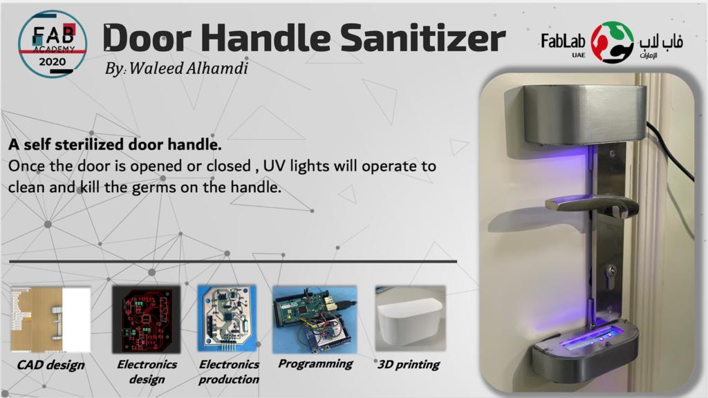
For my project and through the Corona virus panic and with the increase of sterilization tools and equipment demand, my idea is to have self sterilization door handle, so that once the door is opened or closed the UV light will be operated to clean and kill the germs on the handle. As we are aware that the procedure of maintaining your hand clean is an endless loop, we might touch any surface unconsciously from time to time and rather than getting ourselves trapped in this loop, is to make sure that those surfaces are clean.
Idea Sketch
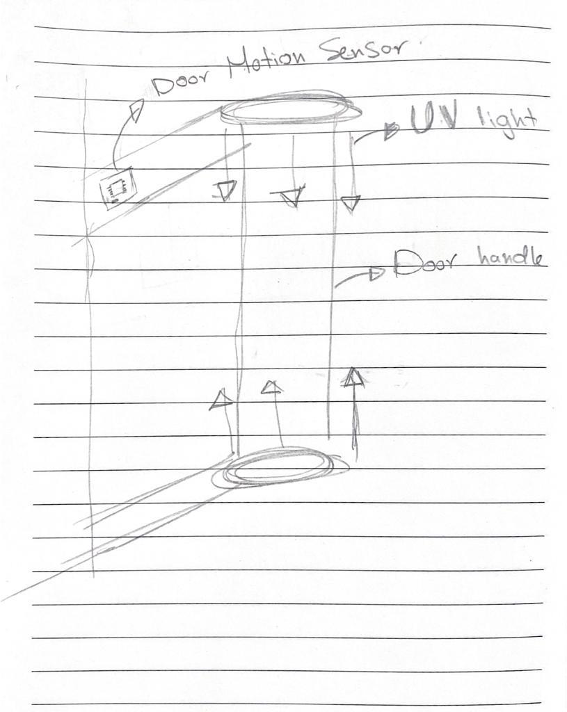
This is a simple sketch of the main components the potential project will consist of:
1- Door Motion sensor & microcontroller, that will be responsible to trigger when the door is open.
2- UV light, will be operated once it receives the signal that the door is opened
3- Door handle frame, design a door handle frame.
Measuring the door movement
One of the main question I need to answer in this project is how to detect the movement of the door so that the device will operate once the door get beck to rest.
after searching in the internet to find the optimal and effective way to measure the movement of the door, I found out that the best way would be by using the accelerometer and the gyroscope, the accelerometer is an electromechanical device used to measure acceleration forces, and the Gyroscope is a device that can measure and maintain the orientation and angular velocity of an object, which led me to select the MPU 6050 as the main sensor to measure the movement of the door.
MPU 6050 sensor
MPU6050 sensor module is complete 6-axis Motion Tracking Device. It combines 3-axis Gyroscope, 3-axis Accelerometer and Digital Motion Processor all in small package. Also, it has additional feature of on-chip Temperature sensor. It has I2C bus interface to communicate with the microcontrollers. It contains a 3 axis gyroscope to measure the anguler rotational velocity along each axis,
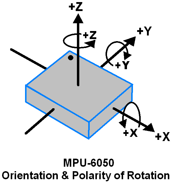
also, it consist of 3- axis accelerometer to measure the acceleration along each axis.
 ,
,
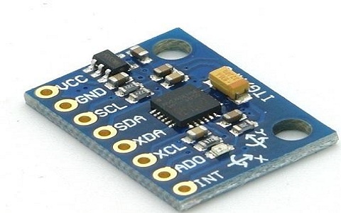
MPU 6050 pinout
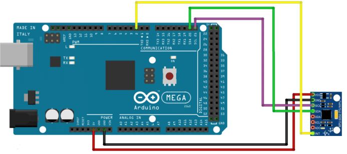
To connect the MPU 6050 with the Arduino, there are main 5 pins to attach:
- VCC = Provides power for the module, can be +3V to +5V. Typically +5V is used.
- GND = Connected to Ground of system.
- SCL = Used for providing clock pulse for I2C Communication.
- SDA = Used for transferring Data through I2C communication.
- INT = Interrupt pin to indicate that data is available for MCU to read.
the other 3 pins I leave it free and it is not required in my project to read more about it you may refer to the link
I started by testing the MPU sensor with the Arduino mega to get myself familiar with sensor, I made the connection as the following:
I started by reading the raw data from the sensor and trying to find out how the MPU works, this by following the instruction in tutorial and run the gyro simple example code,
 /*
     MPU6050 Triple Axis Gyroscope & Accelerometer. Simple Gyroscope Example.
     Read more: http://www.jarzebski.pl/arduino/czujniki-i-sensory/3-osiowy-zyroskop-i-akcelerometr-mpu6050.html
     GIT: https://github.com/jarzebski/Arduino-MPU6050
     Web: http://www.jarzebski.pl
     (c) 2014 by Korneliusz Jarzebski
 */

 #include <Wire.h>
 #include <MPU6050.h>

 MPU6050 mpu;

 void setup()
 {
   Serial.begin(115200);

   // Initialize MPU6050
   Serial.println("Initialize MPU6050");
   while(!mpu.begin(MPU6050_SCALE_2000DPS, MPU6050_RANGE_2G))
   {
     Serial.println("Could not find a valid MPU6050 sensor, check wiring!");
     delay(500);
   }

   // If you want, you can set gyroscope offsets
   // mpu.setGyroOffsetX(155);
   // mpu.setGyroOffsetY(15);
   // mpu.setGyroOffsetZ(15);

   // Calibrate gyroscope. The calibration must be at rest.
   // If you don't want calibrate, comment this line.
   mpu.calibrateGyro();

   // Set threshold sensivty. Default 3.
   // If you don't want use threshold, comment this line or set 0.
   mpu.setThreshold(3);

   // Check settings
   checkSettings();
 }

 void checkSettings()
 {
   Serial.println();

   Serial.print(" * Sleep Mode:        ");
   Serial.println(mpu.getSleepEnabled() ? "Enabled" : "Disabled");

   Serial.print(" * Clock Source:      ");
   switch(mpu.getClockSource())
   {
     case MPU6050_CLOCK_KEEP_RESET:     Serial.println("Stops the clock and keeps the timing generator in reset"); break;
     case MPU6050_CLOCK_EXTERNAL_19MHZ: Serial.println("PLL with external 19.2MHz reference"); break;
     case MPU6050_CLOCK_EXTERNAL_32KHZ: Serial.println("PLL with external 32.768kHz reference"); break;
     case MPU6050_CLOCK_PLL_ZGYRO:      Serial.println("PLL with Z axis gyroscope reference"); break;
     case MPU6050_CLOCK_PLL_YGYRO:      Serial.println("PLL with Y axis gyroscope reference"); break;
     case MPU6050_CLOCK_PLL_XGYRO:      Serial.println("PLL with X axis gyroscope reference"); break;
     case MPU6050_CLOCK_INTERNAL_8MHZ:  Serial.println("Internal 8MHz oscillator"); break;
   }

   Serial.print(" * Gyroscope:         ");
   switch(mpu.getScale())
   {
     case MPU6050_SCALE_2000DPS:        Serial.println("2000 dps"); break;
     case MPU6050_SCALE_1000DPS:        Serial.println("1000 dps"); break;
     case MPU6050_SCALE_500DPS:         Serial.println("500 dps"); break;
     case MPU6050_SCALE_250DPS:         Serial.println("250 dps"); break;
   }

   Serial.print(" * Gyroscope offsets: ");
   Serial.print(mpu.getGyroOffsetX());
   Serial.print(" / ");
   Serial.print(mpu.getGyroOffsetY());
   Serial.print(" / ");
   Serial.println(mpu.getGyroOffsetZ());

   Serial.println();
 }

 void loop()
 {
   Vector rawGyro = mpu.readRawGyro();
   Vector normGyro = mpu.readNormalizeGyro();

   Serial.print(" Xraw = ");
   Serial.print(rawGyro.XAxis);
   Serial.print(" Yraw = ");
   Serial.print(rawGyro.YAxis);
   Serial.print(" Zraw = ");
   Serial.println(rawGyro.ZAxis);

   Serial.print(" Xnorm = ");
   Serial.print(normGyro.XAxis);
   Serial.print(" Ynorm = ");
   Serial.print(normGyro.YAxis);
   Serial.print(" Znorm = ");
   Serial.println(normGyro.ZAxis);


   delay(100);
 }
as It is shown in the video that I get the raw data from the sensor, and the numbers changes with the movement of the mpu 6050 accordingly. but still I cant make a good use of the data I’m receiving which to change the code so that I can make use of the data I’m receiving.
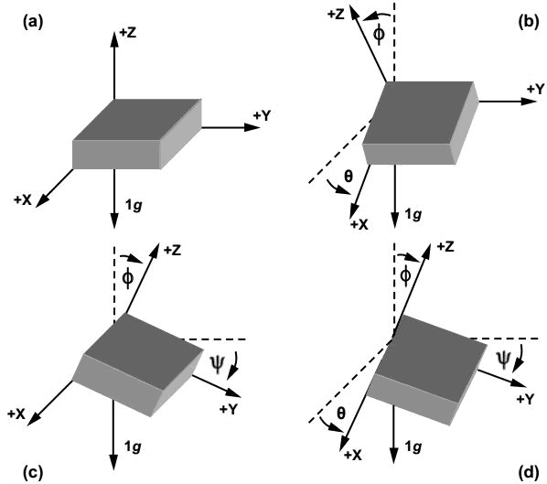
But them I came across a code where it coverts the raw data into pitch, roll and yaw which will easily will help me to detect the movement of the door and it is as the following
/*
    MPU6050 Triple Axis Gyroscope & Accelerometer. Pitch & Roll & Yaw Gyroscope Example.
    Read more: http://www.jarzebski.pl/arduino/czujniki-i-sensory/3-osiowy-zyroskop-i-akcelerometr-mpu6050.html
    GIT: https://github.com/jarzebski/Arduino-MPU6050
    Web: http://www.jarzebski.pl
    (c) 2014 by Korneliusz Jarzebski
*/

#include <Wire.h>
#include <MPU6050.h>

MPU6050 mpu;

// Timers
unsigned long timer = 0;
float timeStep = 0.01;

// Pitch, Roll and Yaw values
float pitch = 0;
float roll = 0;
float yaw = 0;

void setup()
{
  Serial.begin(115200);

  // Initialize MPU6050
  while(!mpu.begin(MPU6050_SCALE_2000DPS, MPU6050_RANGE_2G))
  {
    Serial.println("Could not find a valid MPU6050 sensor, check wiring!");
    delay(500);
  }

  // Calibrate gyroscope. The calibration must be at rest.
  // If you don't want calibrate, comment this line.
  mpu.calibrateGyro();

  // Set threshold sensivty. Default 3.
  // If you don't want use threshold, comment this line or set 0.
  mpu.setThreshold(3);
}

void loop()
{
  timer = millis();

  // Read normalized values
  Vector norm = mpu.readNormalizeGyro();

  // Calculate Pitch, Roll and Yaw
  pitch = pitch + norm.YAxis * timeStep;
  roll = roll + norm.XAxis * timeStep;
  yaw = yaw + norm.ZAxis * timeStep;

  // Output raw
  Serial.print(" Pitch = ");
  Serial.print(pitch);
  Serial.print(" Roll = ");
  Serial.print(roll);
  Serial.print(" Yaw = ");
  Serial.println(yaw);

  // Wait to full timeStep period
  delay((timeStep*1000) - (millis() - timer));
}
Now I can easily measure the orientation around each axis which easily will help me to measure the door movement.
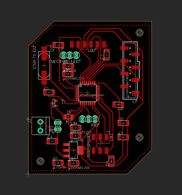
The board Fabrication
I designed only one main board that would control the device with atmega328, I used eagle software to design my board as always,
- Attaching the female header for MPU 6050 which is connecting to SDA, SCL, GND, VCC, and PD4 pins in the ATmega 328.
- Power jack to supply the board with an external power source.
- Male headers for the UV LED strip connecting to a power transistor to control the operation of the UV light.
- PIR male headers for future project improvement to connect PIR sensor.
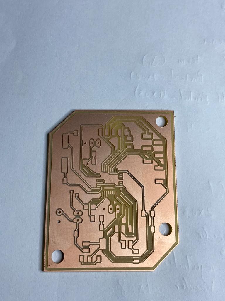
the board after milling,
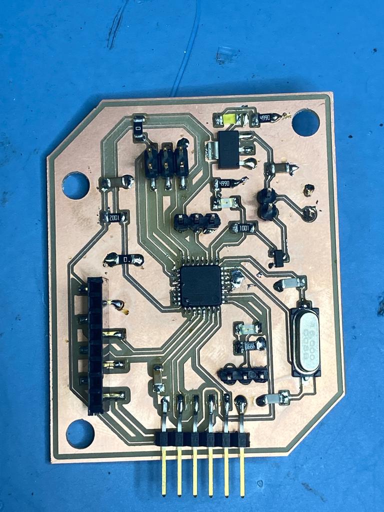
the board after soldering the component needed,
3d designed
The device will consist of 2 main parts, the upper and lower part, it was designed to be attached on the door handle with a screw,
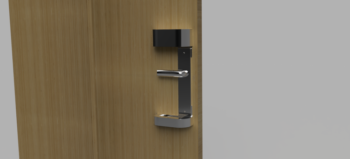
the upper part will be the main part which will curry the board along with the MPU 6050 sensor that will detect the motion of the door with the UV led strip, and the lower will curry the battery along with the extended UV led strip.
First prototype
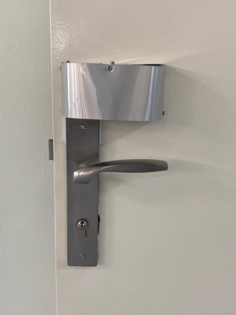
at the beginning I decided with my guru hashim nabil to use the 2mm aluminum sheet for the cover of the device, hoping that it will match the door handle color, I cutted the sheet with the shopbot,
after assembling the device it turned out that it was not a good idea, the sheet is too thin for a cover and to fix it as cover it needs a lot of screws to mount it which made it look ugly, and rather than using a sheet, aluminum cube would be a better choice,
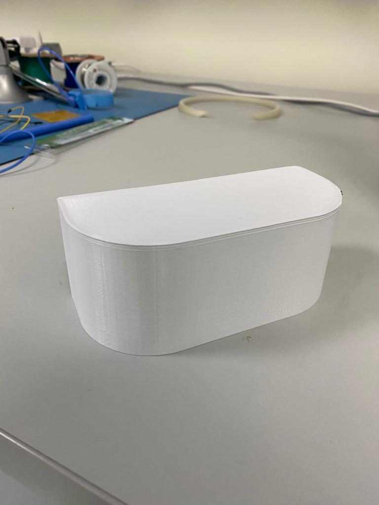
The final prototype
after the first failure trial, I decided to just go with the 3d printing, rather than using the aluminum sheet, and the final results was quite impressive.
then I just assembled all the parts together,
and this was the final result.
problems and future improvements
One of the main issues I faced is that the device won’t operate unless it is connected to the computer to the serial monitor, and it won’t receive any readings from the MPU6050.
also, I tried to use the aluminum as the outer cover of the device but it did not look good enough which led me to replace it with a 3d part.
also, I found out that the battery need to be recharged after 4 hours and In future I’m planning to figure out a way to auto charge the battery again once the door gets be to rest.
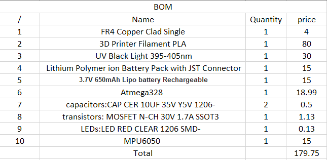
BOM
The table below shows the material and components used in the project, I used the coreldraw software to design the logo
update 19/11/2020
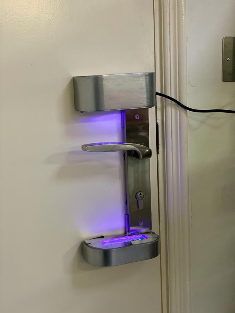
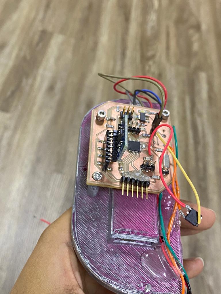
Project integration
here I was testing the code above with UV light and the board with the 3d print integration where it can show the operation of the device once it rotates,
I have externally soldered a power transistor, where built in one was burned.
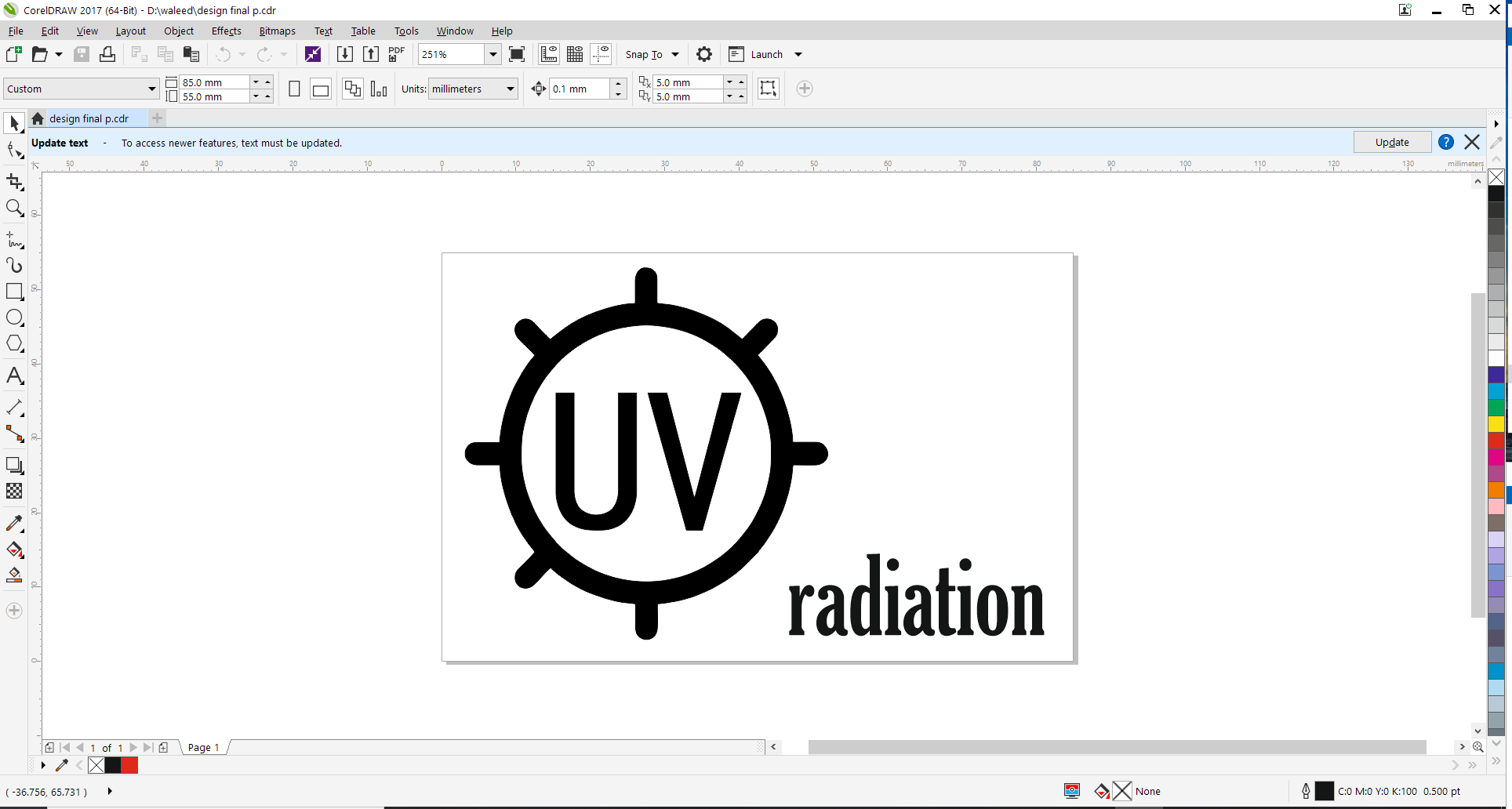
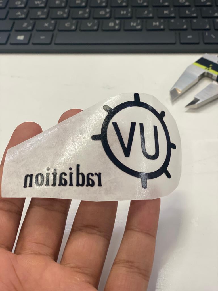
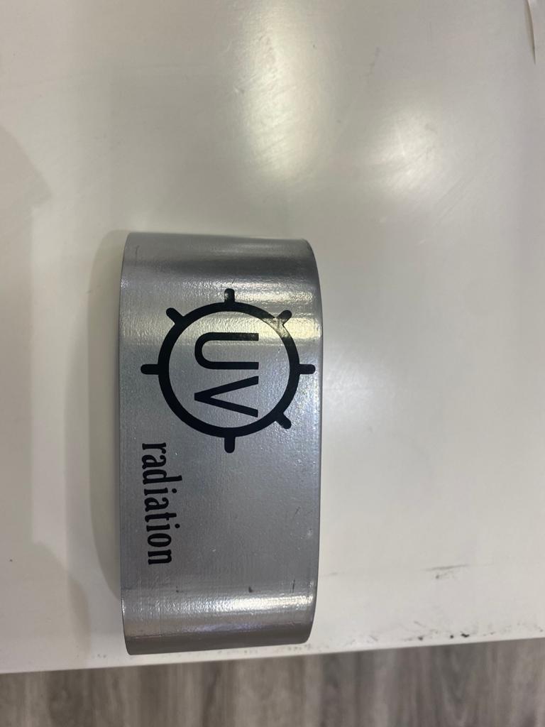
project logo
I designed a simple logo for the project where I have used coreldraw software,
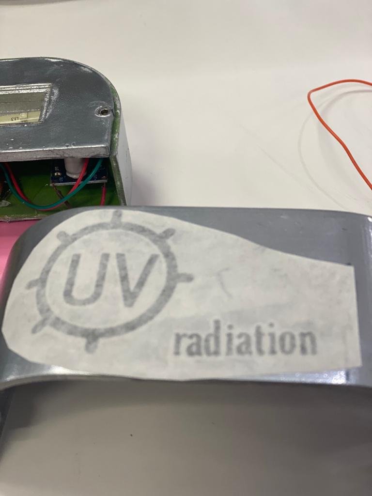
then prepared the file for cutting following the steps in week4 where I have to change the outline thickness to be hairline, once I was done with the design I started preparing the gs-24 machine for cutting, this is first by installing the roll and adjusting the blade, and the cut force to be 70 gf, once the cut was finished I used the tweezers to remove the unwanted parts,
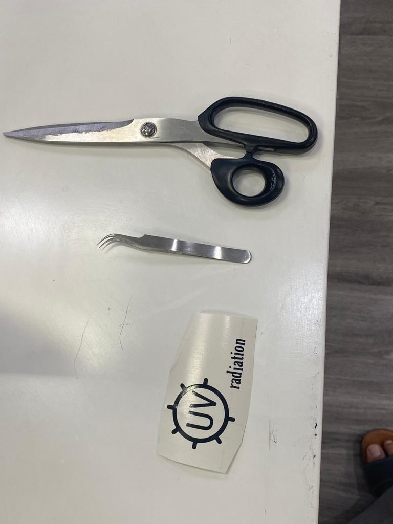
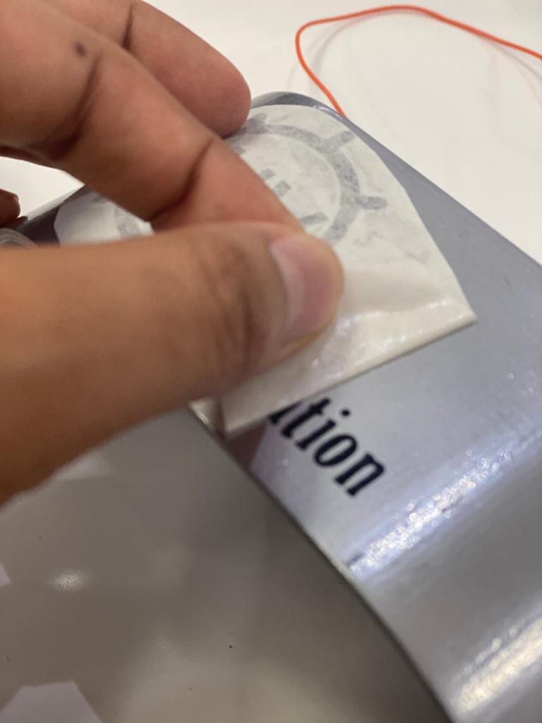
then using the masking tape,

Download Files

This work is licensed under a Creative Commons Attribution-NonCommercial-ShareAlike 4.0 International License.