5. Electronics production
So, the aim of this week was to expose ourselves to the monofab Srm-20 where we have to mill and fabricate our ISP programmer board circuit which will be used later to program my electronics boards.
Group Assignment
Our group assignment can be found here
Downloading ISP Traces
We were advised by Hashim Alsakkaf to follow brian’s documentation to fabricate our own ISP programmer.
to do so
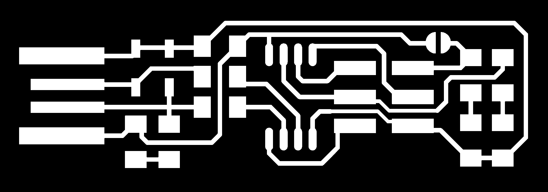
First, I downloaded the PNG file for traces.
then, downloaded the PNG file for the outline

Fab Modules
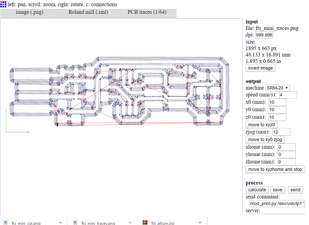
I used the fab modules, to convert the PNG traces to rml files, to do so all what you have to do is the following: 1. Upload the traces PNG file to the Fab modules website. 2. Choose the output format, which is in my case is roland mill (rml format). 3.Choose the process, for the inner traces it is (1/64) and for the outline I used the (1/32). 4. Then the final setting where you need to select the machine type and make sure that the home position is at 0s, and press calculate.
Setting Up the srm_20
It was a bit tricky to get access to the machine physically, the closed frame of the machine made it difficult to change the mill bit, to start cutting the traces we needed to replace the mill bit with 1/64 mill bit, to do so I use Allen key to replace the mill bit, once the mill bit is replaced, I set the x and y axis to the required home position
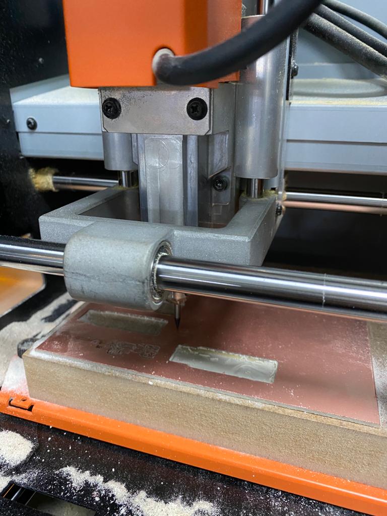
then I started setting up the home position of the z axis, this was tricky one where you have to release the mill bit while holding it so it does not get broken then carefully bring the mill bit down all the way and make sure it hits the copper board, once I was satisfied with home z axis position I uploaded the traces rml file and start cutting the file, once the traces process was over, I replaced the mill bit with 1/32 for the outline cut and I set the z home position repeated the same procedure as before, but this time I made sure not to change the x and y home position.
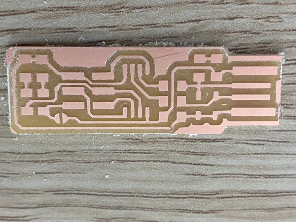
once I uploaded the outline rml file, and the cut process was over I was not really happy about the result as you can see from the picture.
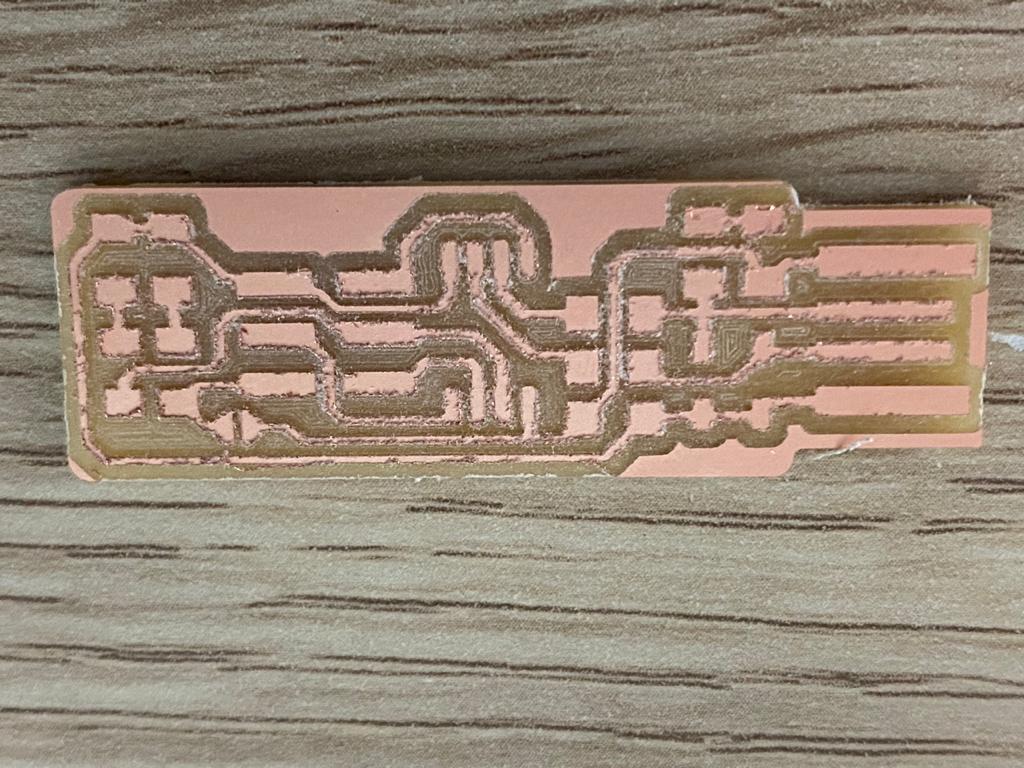
After consulting our main instructor Hashim Alsakkaf he pointed out that the z axis home position set up was the problem, to be honest I was not sure about it, Anyway, I repeated the process again but this time I replaced the 1/64 mill bit where I had some doubt that it might be the problem along with double checking z axis home position this is by pressing the 1/64 mill bit firmly towards the copper board.
THIS time I was really happy about the result.
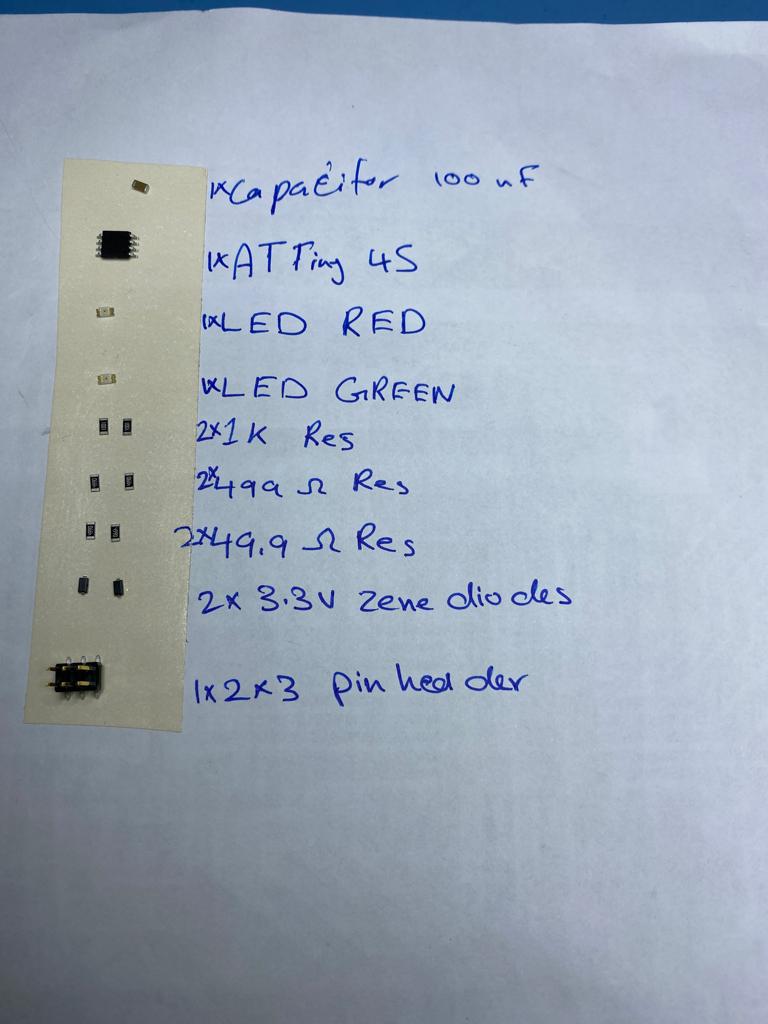
Soldering the components of the ISP board
I collected and listed all the components of the ISP board
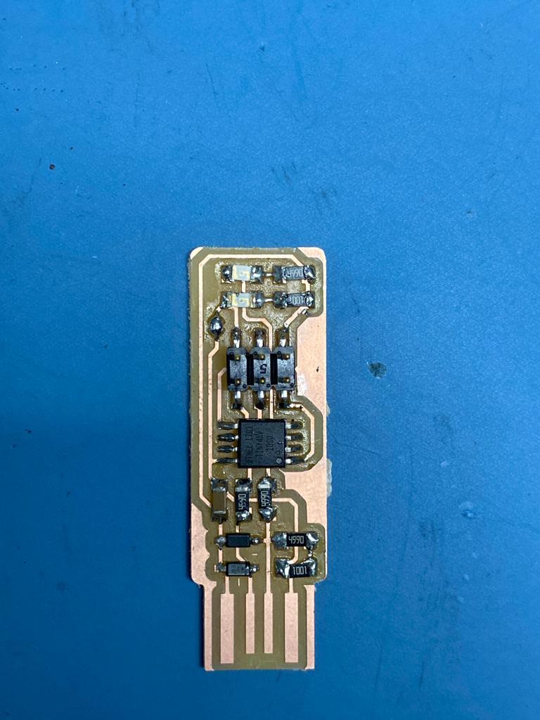
Even though it was not the first time soldering the smd components I faced some trouble dealing with components, where it might slip away even though I was using a tweezer, nevertheless I could manage soldering all the components paying attention to the polarity and the orientation of some parts such as the Led where it has a small green line to indicate the negative polarity, also the diode and the ATTINY.
Programming my ISP
Setting up the laptop
So to start with programming my own ISP, I had to install different softwares to set up the development platform which gave me a headache!
So this was done by following Brian’s tutorial with alot of patience where you have to fulfill the following steps:
1- Install the Atmel GNU Toolchain
2- Install GNU Make
3-Install avrdude
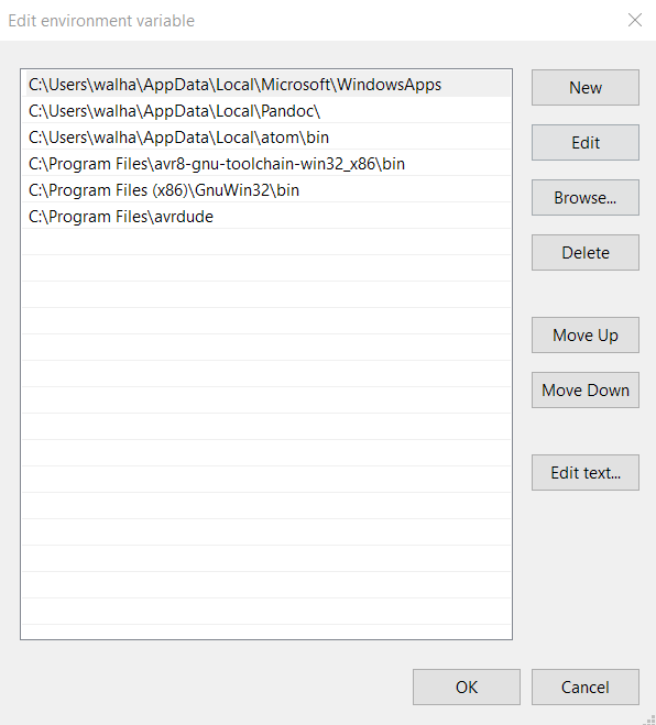
4-Update your PATH
WARNING! at this point I faced a problem at this stage which took an hour to solve where the paths in Brians tutorial does not match mine so I needed to update it accordingly
5-Install Drivers for your Programmer
Program the Attiny 44
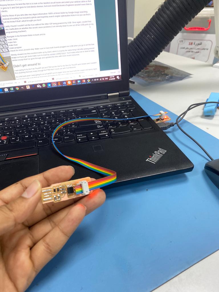
I needed to use Hashim Alsakkaf ISP programmer taking in mind all the instructions that was pointed out by Brian, to connect hashim’s programmer to the ISP header on my board. paying attention to the orientations in which the cable is connected, making sure to get the pins in the right order, to ease it make sure that pin 1 which is marked in the programmer board is connected to the other ISP pin 1,
this was followed by running the following commands to program my board:
make flash to erase my chip, and program it with the .hex file that was built before.
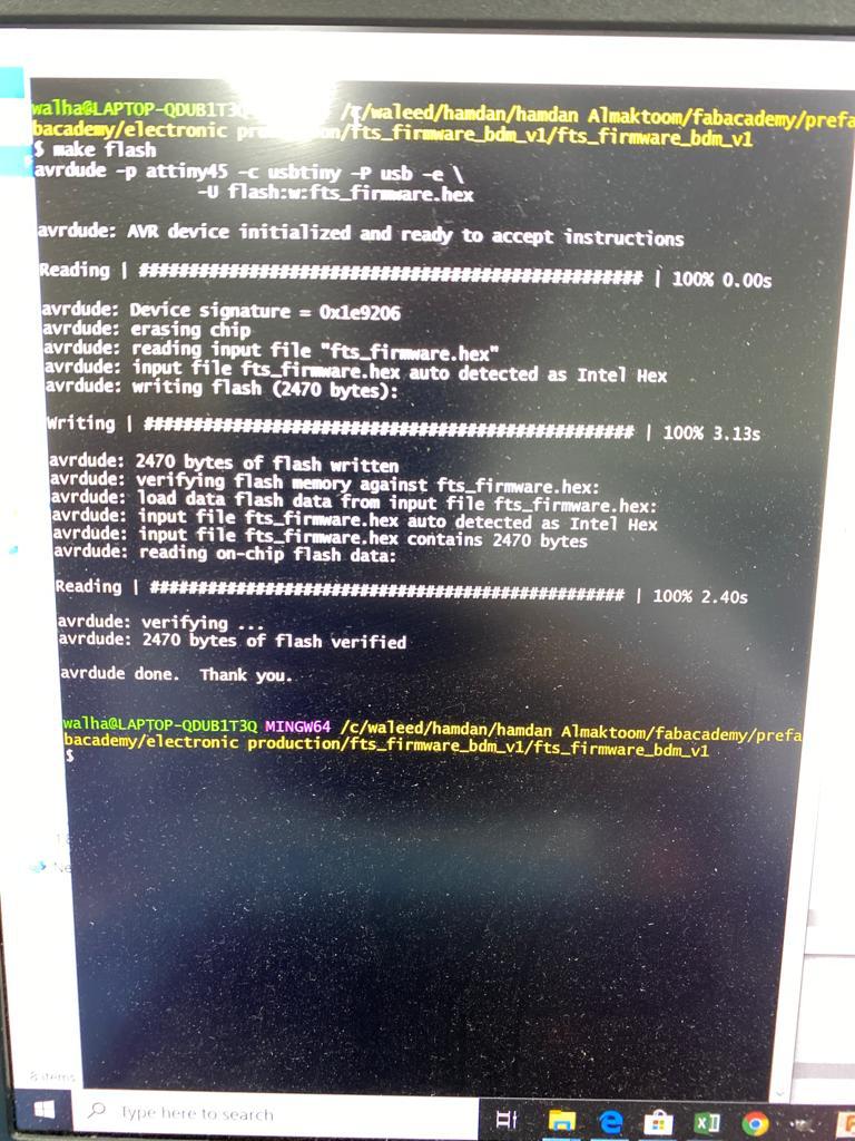
you could easily see the progress bars while the avrdude erases the chip, program and verify it,
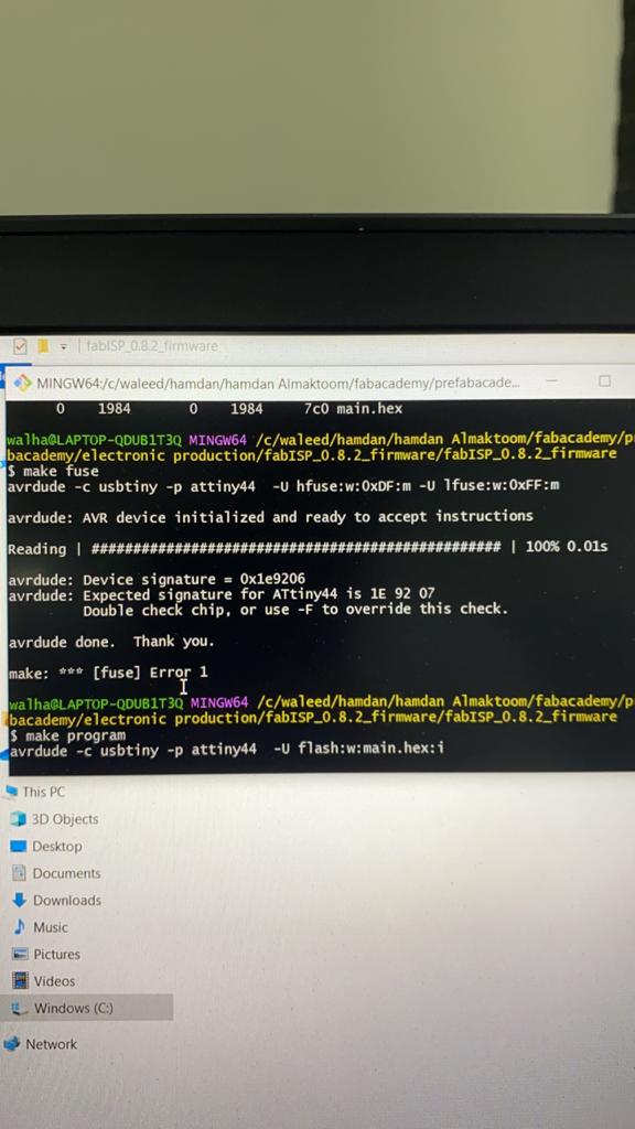
this was followed by set the configuration fuses, which will be in two main stages as follow:
- make fuses to set up all of the fuses except the one that disables the reset pin , which will allow me to check that the board works as a USB device, but it won’t yet be able to program other boards this process will.
once I was done with this step, now it is time to make sure that the USB on my board works, before blowing the fuse that will enable it as a programmer, this is done by plugging the ISP directly to the computer.
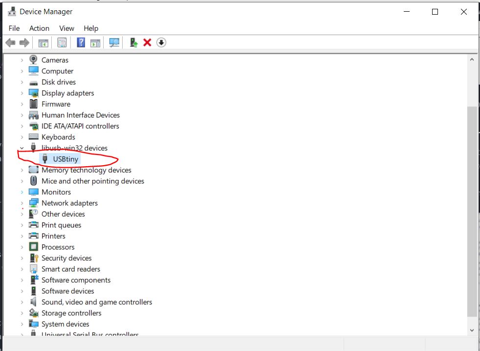
then in the Windows lists USB devices in Device Manager (Start → Control Panel → System → Device Manager), you should find the USBtiny appears in the list telling that my ISP is detected which means that the board is working.
Once I was sure that my board is working now I reached to the final step, this will disable the ability to reprogram my board in future that is why I double checked that my board is working.
- I just Connected the ISP programmer to my board one more time, and run make rstdisbl to set up the fuse that disables the reset pin.
ISP working
I used the ISP to program my board in the in Embedded programming week