9.Embedded programming
This week is about programming, so the journey will start by getting used to C language and then try to program my board.
Group assignment:
You can find our work in the group assignment where we have to compare the performance and development workflows for different microcontroller families please visit the group page.
C language
Before getting ourselves to learn how to program our microcontroller, we were introduced to C language by our instructor Hashim Nabil, so basically C language is a powerful general-purpose programming language. It can be used to develop software like operating systems, databases, compilers, and so on. C programming is an excellent language to learn to program for beginners. It is a language that is understood by humans, and then it goes through a process to convert it to understandable machine language which is Object language through a Compilation process.
Attiny 44
As per this week we have to go through the datasheets of the microcontrollers we gonna use, to learn how they operate and what is the recommended power and the pin we gonna use, I downloaded the datasheet from the Link, I was shocked that the datasheet consist of 229 pages, and no way I can to go through them all. But it turned out that I only need to dig into a specific information that I need and I don’t have to go through all the pages.
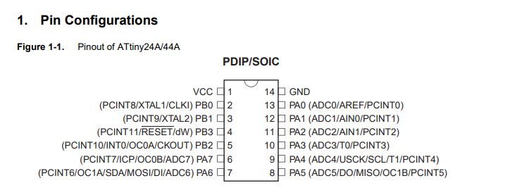
As we can observe from the Pin configuration, the attiny44 has a VCC PIN and GND pin for the power, Also it has I/O pins ports A and ports B with internal pull-up resistors, the operating voltage to run the attiny44 is 1.8V to 5.5V,
Programming my board Attiny44 with C
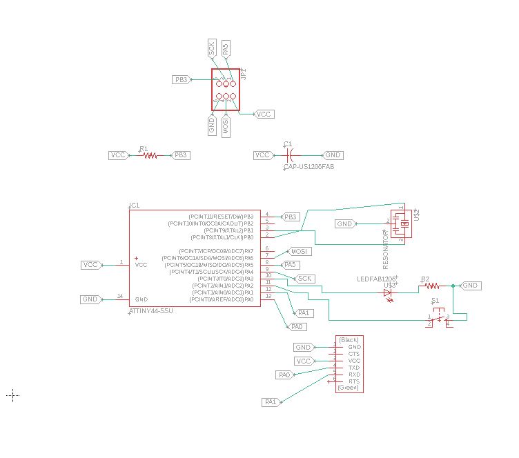
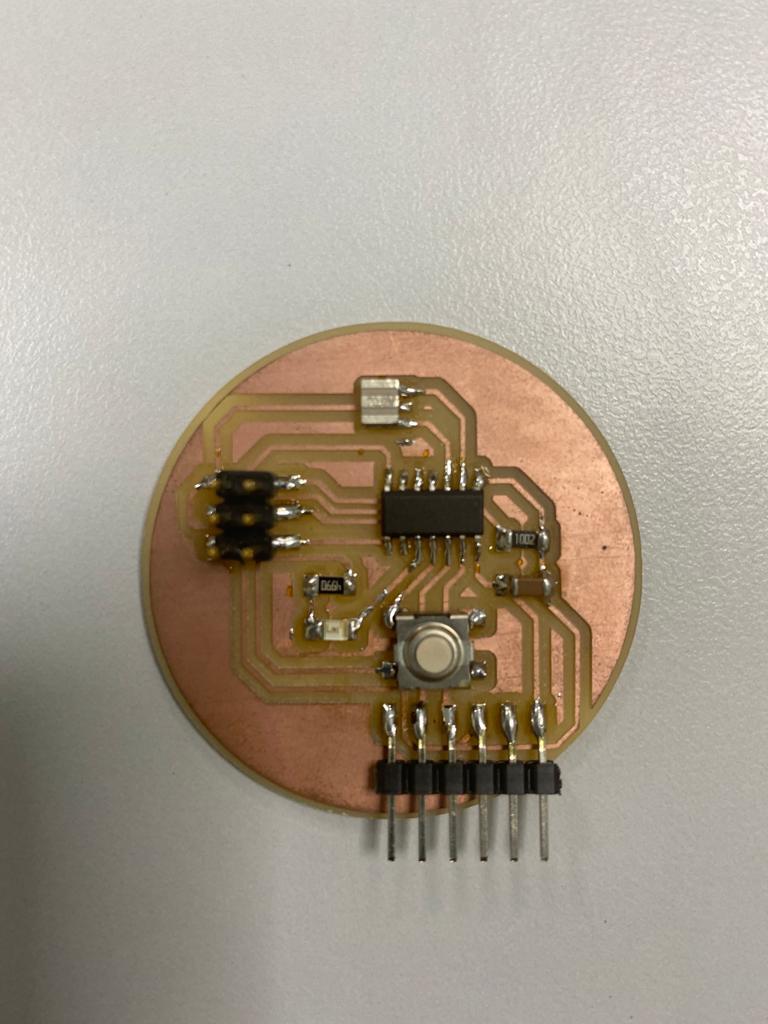
Using my programmer to upload the code to my board I have designed, and following the same steps previously, I programmed my board so that when I press the push button the LED will light Up, the led is attached to pin PA3 and the push button is attached to PA2.
to program the board using C language there are three important register to learn about:
The Data Direction Register(DDRx) which determines whether the pin is set as Input or Output, as default all pins are inputs and to set it as Output we set 1 in the Data Direction Register (DDR)
For example:
so let say we would like to assign the port B5 in the Atmega328 as an output:
DDRB = 0b00100000
The port output register(PORTx) which tells whether the port is HIGH OR LOW when it is used as an Output
The port input register(PINx) used to read the input value
to read more about it you may refer to the link
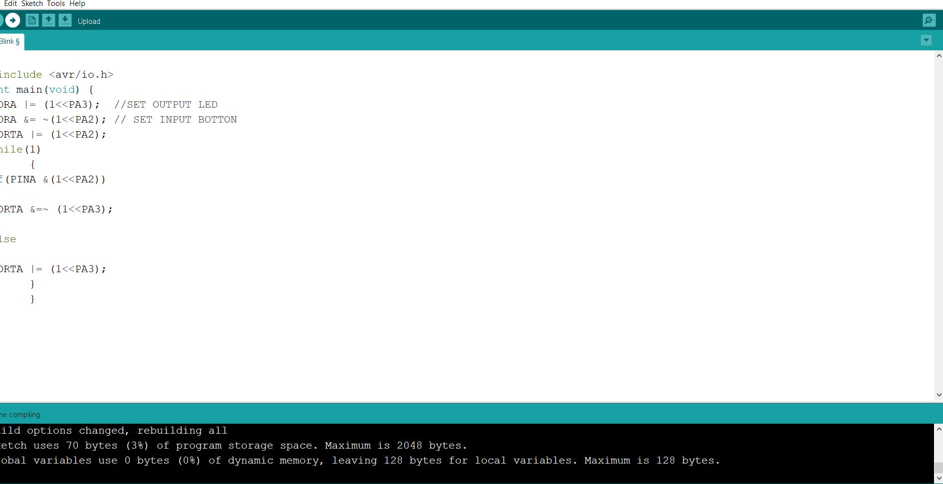
Once I got myself familiar with the Data register I started programming my board by trying to light up the Led which once the push button is pressed,
I used arduino IDE to run my code,
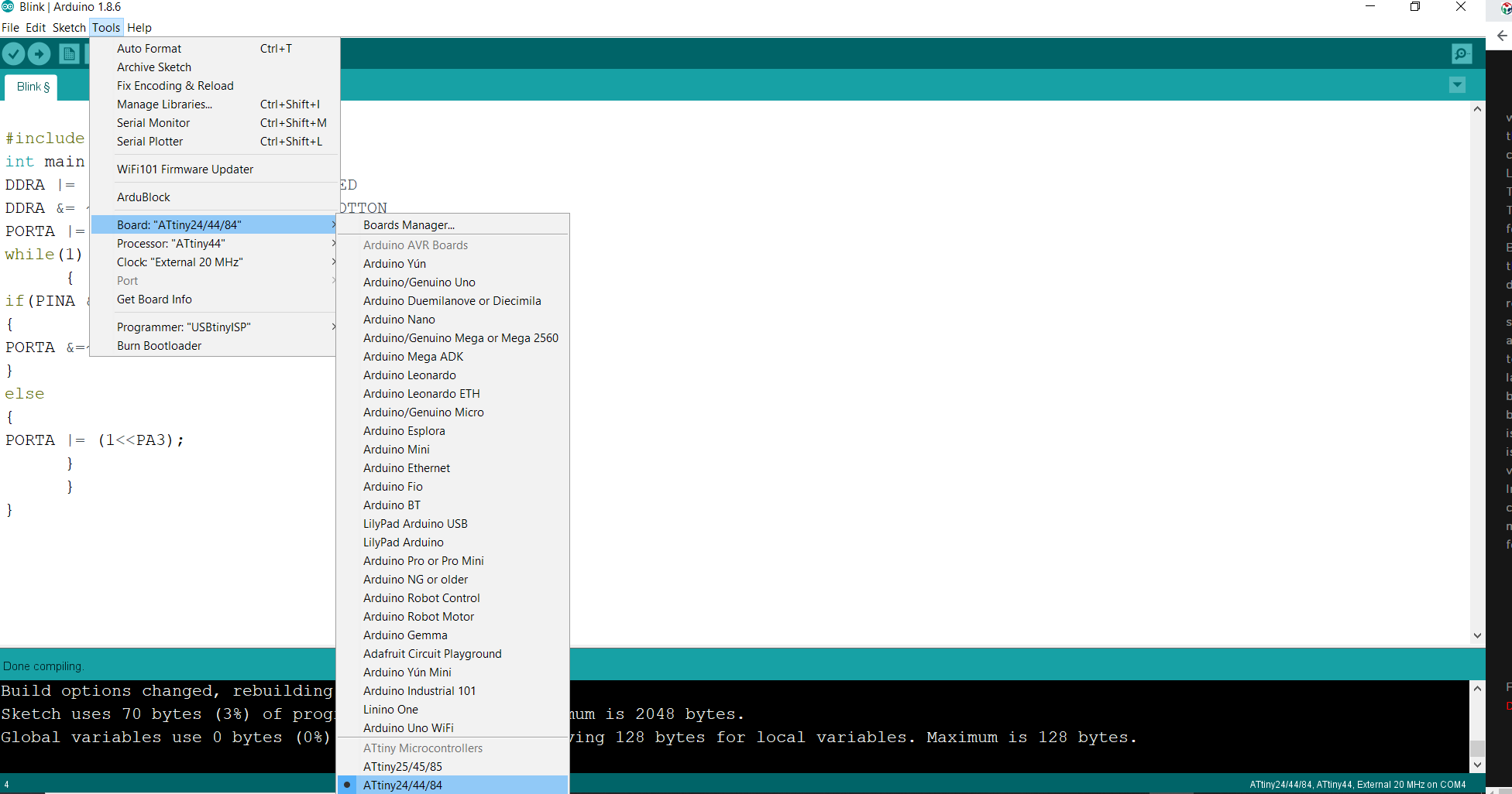
to use the board you have to burn the Bootloader by going to Tools>Burn Bootloader, it is done only one time,
then selecting the following settings:
Attiny 44 as the main board from the tools tab,
Processor>Attiny44,
Clock>External 20MHz
Programmer>USBtinyISP
Sketch>Upload
#include <avr/io.h>
int main(void) {
DDRA |= (1<<PA3);  //SET OUTPUT LED
DDRA &= ~(1<<PA2); // SET INPUT BOTTON
PORTA |= (1<<PA2);
while(1)
      {
if(PINA &(1<<PA2))
{
PORTA &=~ (1<<PA3);
}
else
{
PORTA |= (1<<PA3);
      }
      }
}
programming atmega 328p with Arduino IDE
I was lucky to have some experience working with the arduino boards such as Arduino uno and Arduino mega, due to the fact that I found the arduino IDE much easier to program the boards rather then plain C which requires deep knowledge in C language and due to the huge Arduino community that is available to support you, I decided program my own board Atmega328p that I have fabricated in the input week,,

Lighting up RGB Led
I started by changing the color of the RGB LED, to do so I had to refer to my Board schematic to indicate which pin numbers the RGB LED is attached to,
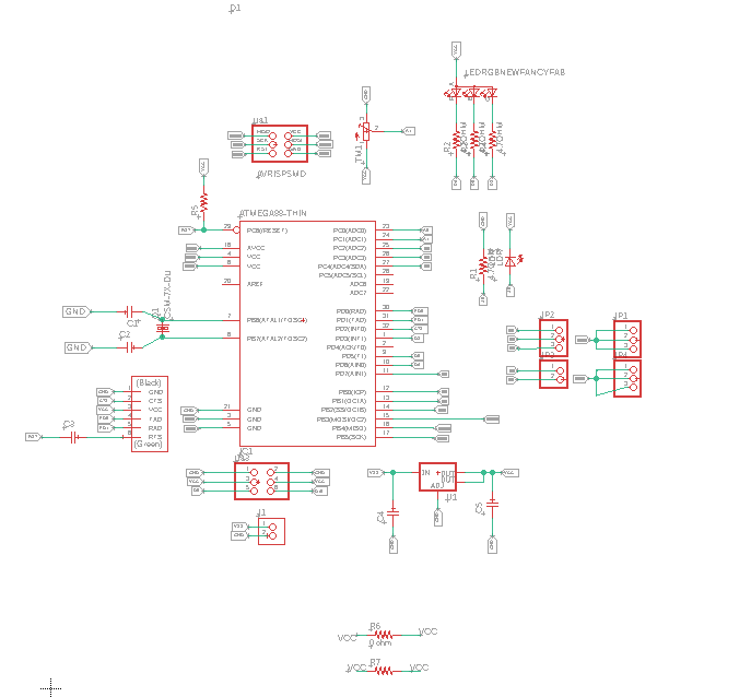
We can see from the schematic that the RGB is attached to pin PD3,PD5 & PD6, which correspond to D3, D5, D6 pins in the arduino uno, you can figure that from Atmega328p arduino uno pinout picture

then I started programming my board using the ftdi cable after the bootloader was burned ( refer to attiny44 step) and with the help of the arduino community tutorial, I managed to light up my built in rgb led using the following code,
the following syntax are used:
int red_light_pin= 11; declaring variable for RGB red light pin which connected to pin 11.
int green_light_pin = 10; declaring variable for RGB green light pin which connected to pin 10.
int blue_light_pin = 9; declaring variable for RGB blue light pin which connected to pin 9.
pinMode(red_light_pin, OUTPUT); syntax is used to configure the red_light_pin to behave as an OUTPUT.
RGB_color(255, 0, 0); call RGB color function
void RGB_color(, ,) declare a function named RGB_color
analogWrite(, ); to write an analog value (PWM wave) to a pin.
int red_light_pin= 11;
int green_light_pin = 10;
int blue_light_pin = 9;
void setup() {
  pinMode(red_light_pin, OUTPUT);
  pinMode(green_light_pin, OUTPUT);
  pinMode(blue_light_pin, OUTPUT);
}
void loop() {
  RGB_color(255, 0, 0); // Red
  delay(1000);
  RGB_color(0, 255, 0); // Green
  delay(1000);
  RGB_color(0, 0, 255); // Blue
  delay(1000);
  RGB_color(255, 255, 125); // Raspberry
  delay(1000);
  RGB_color(0, 255, 255); // Cyan
  delay(1000);
  RGB_color(255, 0, 255); // Magenta
  delay(1000);
  RGB_color(255, 255, 0); // Yellow
  delay(1000);
  RGB_color(255, 255, 255); // White
  delay(1000);
}
void RGB_color(int red_light_value, int green_light_value, int blue_light_value)
 {
  analogWrite(red_light_pin, red_light_value);
  analogWrite(green_light_pin, green_light_value);
  analogWrite(blue_light_pin, blue_light_value);
}