15. Networking and Communications
Group Assignment
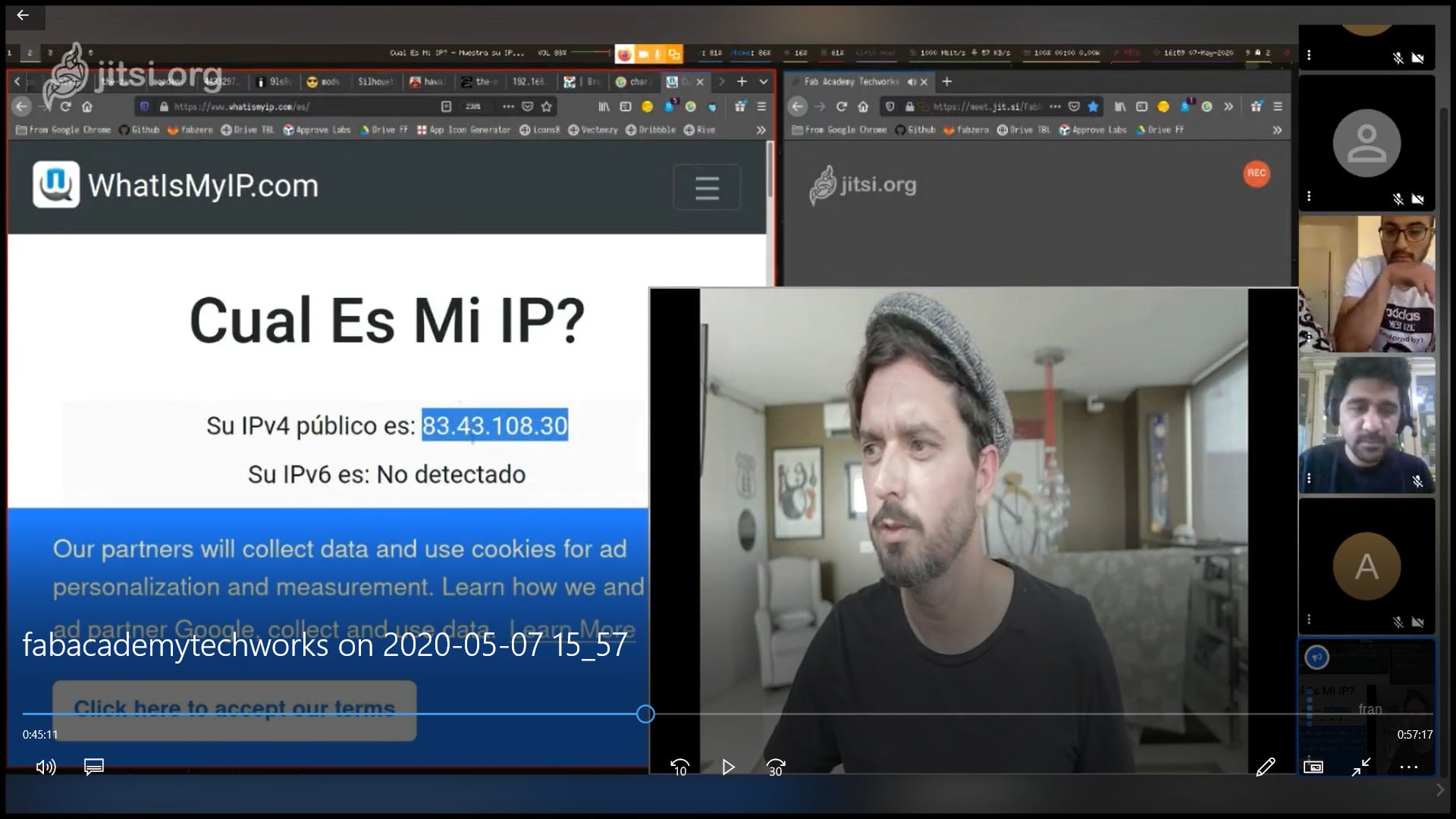
We complete the group assignment in a group call. Using Netcat (nc) under linux, we connected two PCs in two different locations, Frank in Spain with Faisal in Jordan. This is a simple and basic way to create communication beween two PCs to send and receive raw data. Frank used linux, and Faisal used Windows Subsystem for Linux.
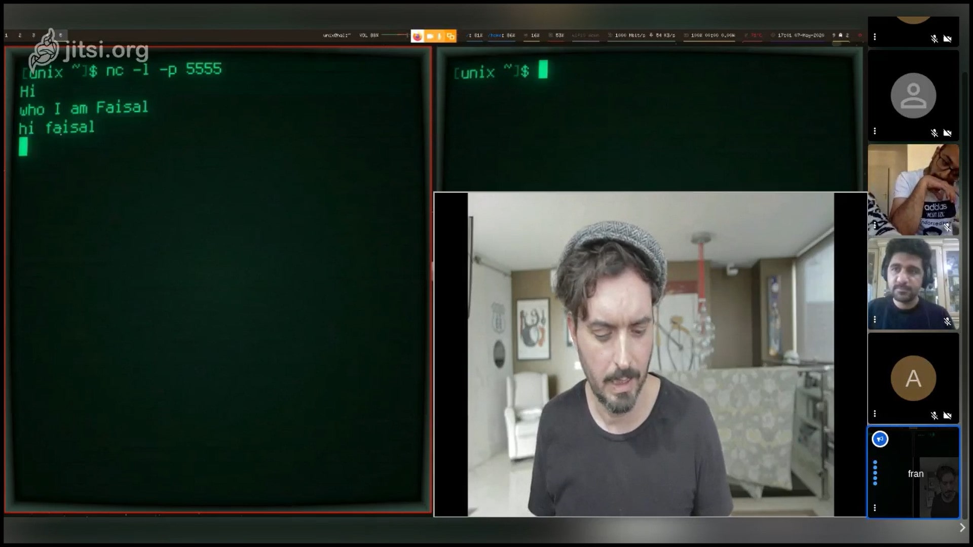
Step 1 : Frank opened a port in his PC terminal, the port number is 5555. He used the command “nc -l -p 5555”, l for listen and p for port. Now the terminal will be listening to port number 5555 in TCP protocol.

Step 2 : Then Frank shared his IP address with Faisal. To open connection with Frank’s open port, Faisal used the command “nc 83.43.108.30 5555”. This command will communicate with port 5555 in the PC at address 83.43.108.30
Step 3 : Frank and Faisal had this conversation
    Faisal: Hi
    Frank: who
    Faisal: I am Faisal
    Frank: hi Faisal
Step 4: To close the terminal port, Frank pressed “CTRL + C”. This will close communication between the terminals.

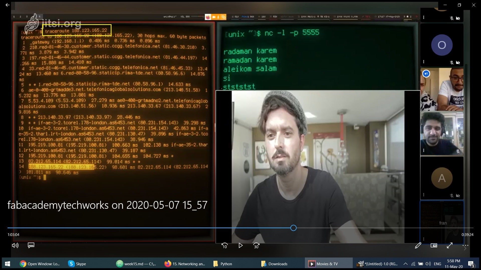
To trace the connection path between the two PCs, we used the command “traceroute 188.123.165.22”, where the IP address is for the destination PC. In the image below we can see that there were 12 PCs or stages between source and destination PCs.
Week Assignment
For this week i want to connect the board i have done in the week7 with bluetooth to open and close the LED using phone application.
Bluethooth device HC-05
HC-05 Bluetooth Module is an easy to use Bluetooth SPP (Serial Port Protocol) module, designed for transparent wireless serial connection setup. … HC-05 Bluetooth module provides switching mode between master and slave mode which means it able to use neither receiving nor transmitting data.
There are three main parts to this project. An Android smartphone, a Bluetooth transceiver, and an Arduino.
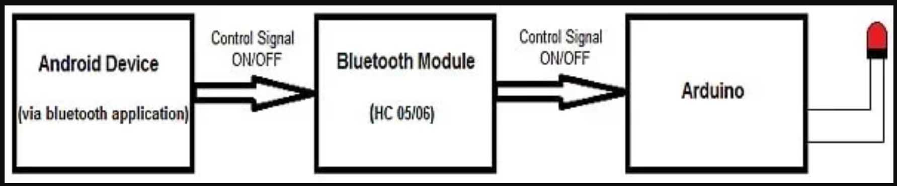
HC 05/06 works on serial communication. The Android app is designed to send serial data to the Arduino Bluetooth module when a button is pressed on the app. The Arduino Bluetooth module at the other end receives the data and sends it to the Arduino through the TX pin of the Bluetooth module (connected to RX pin of Arduino). The code uploaded to the Arduino checks the received data and compares it. If the received data is 1, the LED turns ON. The LED turns OFF when the received data is 0. You can open the serial monitor and watch the received data while connecting.
_ So first i have linked the bluethooth device to the board i had cut in the week7
Note: Don’t connect RX to RX and TX to TX on the Bluetooth and Arduino. You will receive no data. Here, TX means transmit and RX means receive.

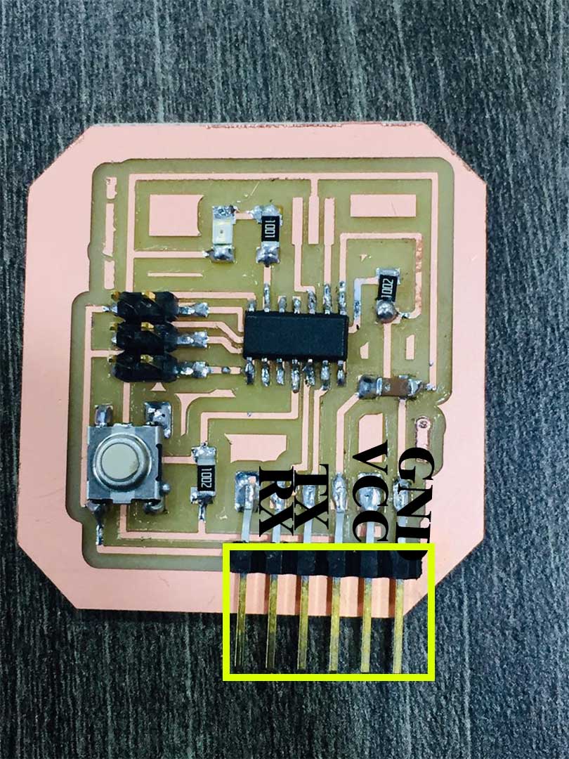
Bluetooth PINOUT HC-05

FTDI PINOUT :

Connect the Bluetooth with FTDI as shown bellow :
| Bluetooth | FTDI |
|---|---|
| Gnd | GND |
| VCC | VCC |
| TX | RX |
| RX | TX |
Note : Connect TX and RX to the Ftdi after you Programming the board with Arduino.
Programming the Board
First :Uploading the Sketch to Arduino.
Step 1: Check on which pin you have connected the LED with ATtiny:
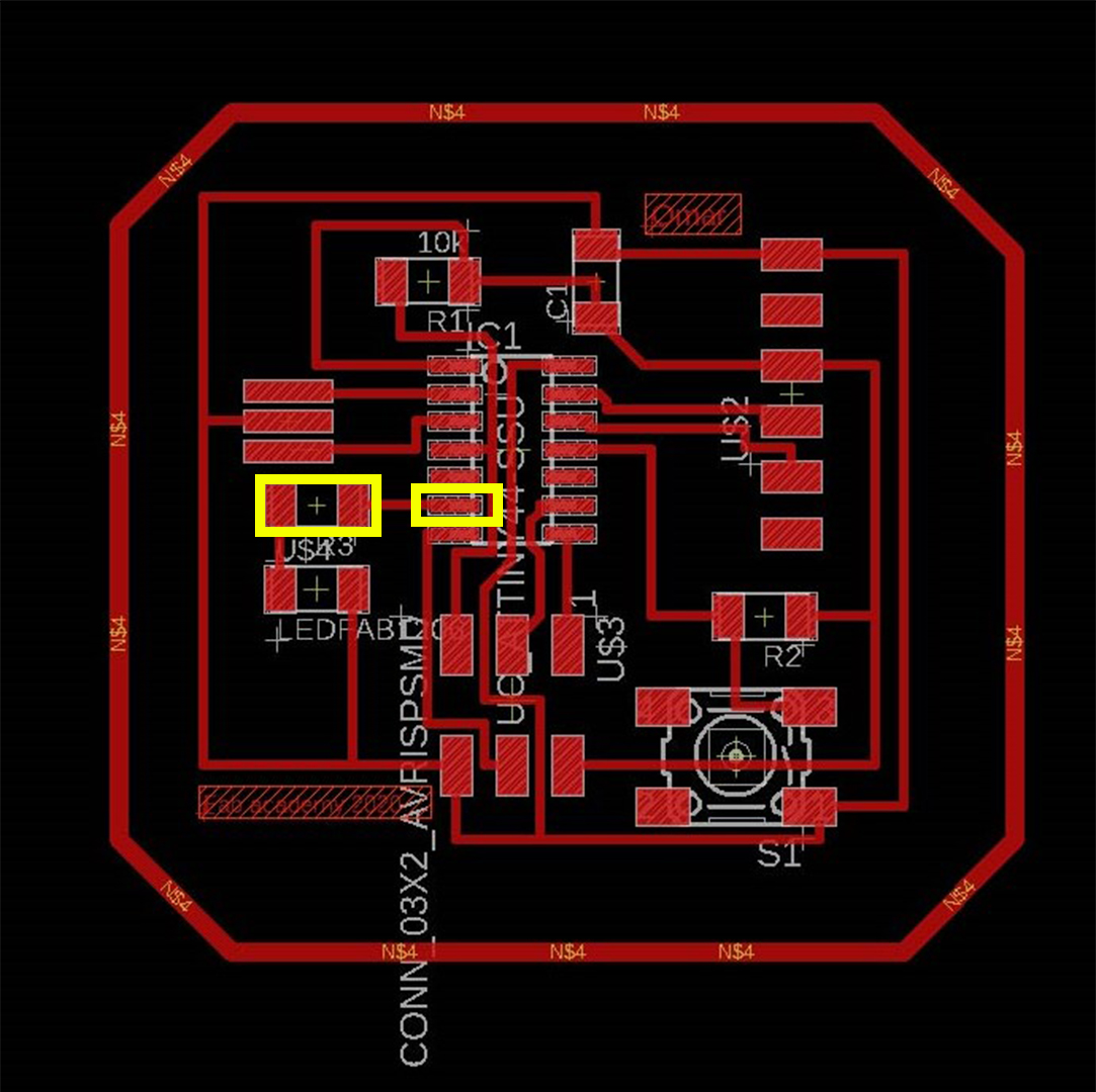
In my board i connected the LED to pin (PA7) and PA7 in Arduino Is (7)

      #include<SoftwareSerial.h>
      char state ;
      /* Create object named bt of the class SoftwareSerial */
      SoftwareSerial bt(0,1); /* (Rx,Tx) */

      void setup() {
      bt.begin(9600); /* Define baud rate for software serial communication */
      pinMode(7,OUTPUT);
      }

      void loop() {

      if (bt.available()) /* If data is available on serial port */
      {
      state= bt.read();


      if (state == '0'){
      digitalWrite (7, HIGH);

      }
      if (state == '1'){
          digitalWrite (7, LOW);

      }
      }
      }
Step 4 : Connect the ISP tp the Board after you connect the bluetooth device to the board.
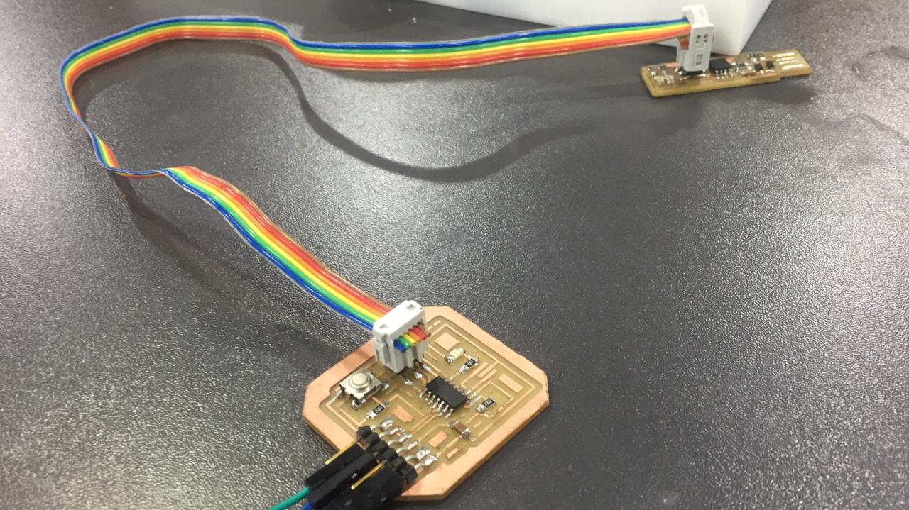
Then Connect the ISP to the power (laptop).
Run the code above :
Installing the Android Application
In this tutorial, I will not cover Android app development. You can download the Android application from here and the source code of the entire project.
-
Download the application from [App Store]https://play.google.com/store/apps/details?id=project.bluetoothterminal&hl=en&gl=US).
-
Pair your device with the HC 05/06 Bluetooth module:
-
Turn ON the HC 05/06 Bluetooth module by powering the Arduino.
- Scan your smartphone for available devices.3. Pair your smartphone to the HC 05/06 by entering default password 1234 OR 0000.
Install the LED application on your Android device. Open the application.
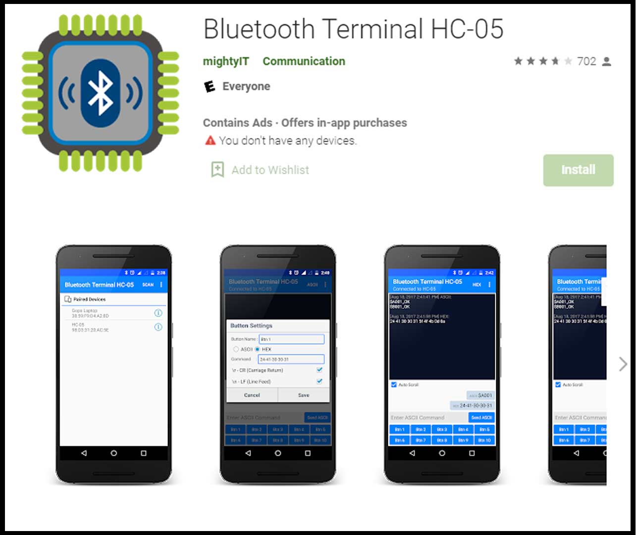
. Press “paired devices”. . Select your Bluetooth module from the list (HC-05/06)
[Pair]
By pressing 0 i will turn off the light and by pressing 1 o will turn on the light.