12. Output devices
Group assignment
In this part we measured the power consumption of a DC motor using a DC motor output board. Power (in Watt) is calculated by P = V x I, where V is the voltage across the load and I is the current passing through the load. To measure voltage, the digital multimeter (DMM) is connected in parallel with the load, and to measure the current passing through, the DMM is connected in series with the load. Remember to move DMM positive test lead to current measuring position before connecting in series with the load.
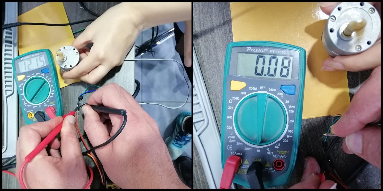
      To calculate the power consumption of the DC motor:

      P = 12.15 x 0.08
      P = 0.972 Watt
      P = 972 mWatt
Week assignment
In this week i have to control a servo motor driver with and without potentiometer using Ardunio UNO and breadboard to get the Assignment done in this phase.
Files:
Useful links
Servo motor (Pinout)
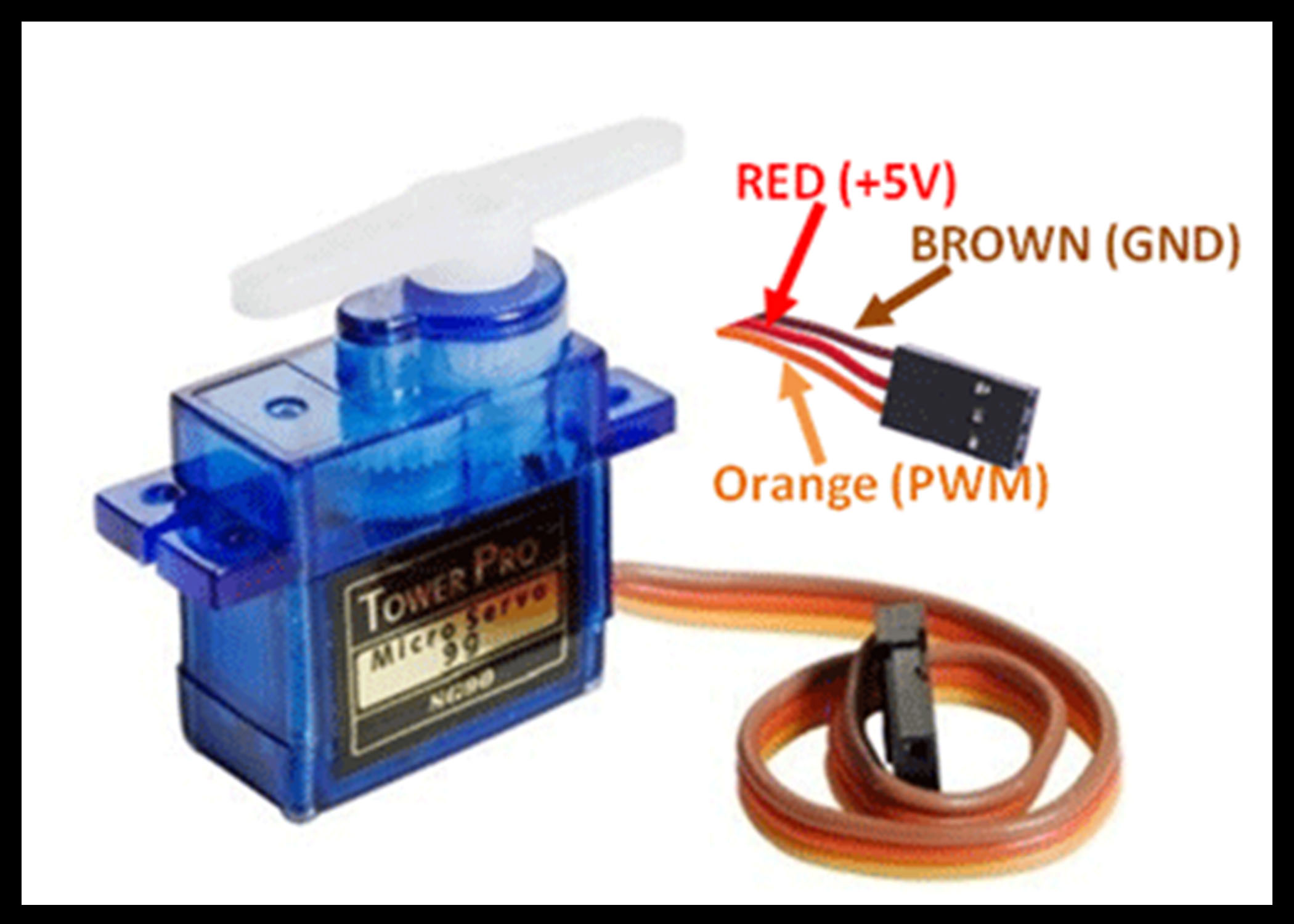
| Wire Number | Wire Colour | Description |
|---|---|---|
| 1 | Brown | Ground wire connected to the ground of system |
| 2 | Red | Powers the motor typically +5V is used |
| 3 | Orange | PWM signal is given in through this wire to drive the motor |
TowerPro SG-90 Features
Operating Voltage is +5V typically
Torque: 2.5kg/cm
Operating speed is 0.1s/60°
Gear Type: Plastic
Rotation : 0°-180°
Weight of motor : 9gm
Package includes gear horns and screws
SG-90 Servo Motor Equivalent:
MG90S Metal Gear, MG995 High Torque Metal Gear, VTS-08A Analog Servo
Rotary-Potentiometer
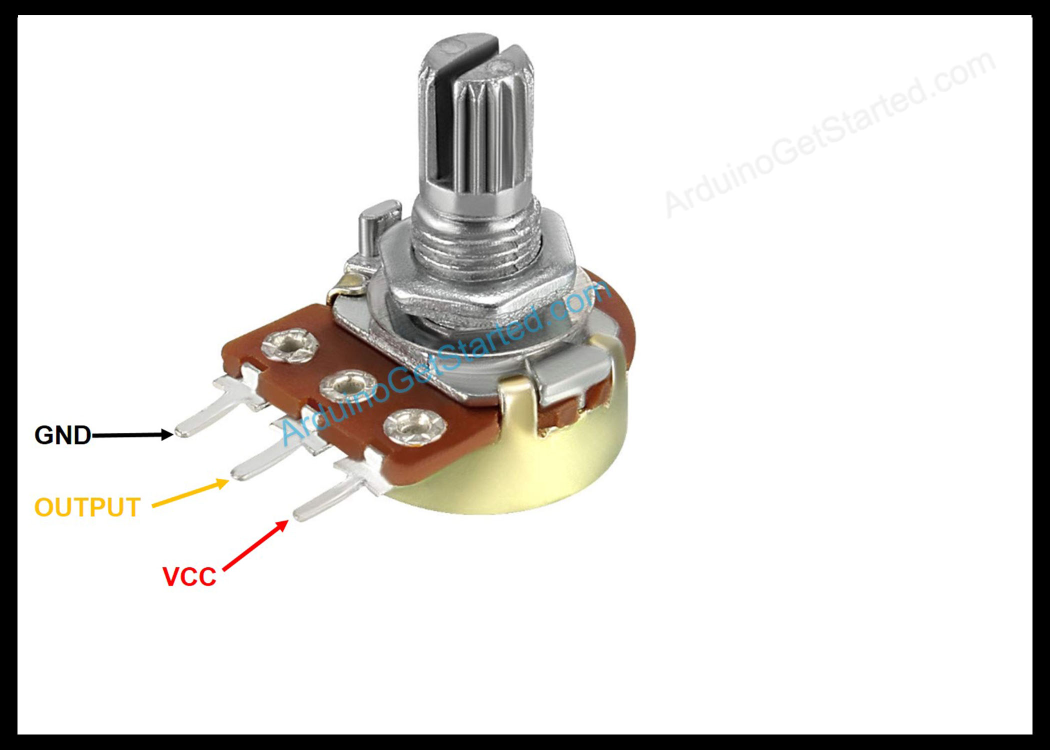
Potentiometers also known as POT. A potentiometer is a three-terminal resistor with a sliding or rotating contact that forms an adjustable voltage divider.
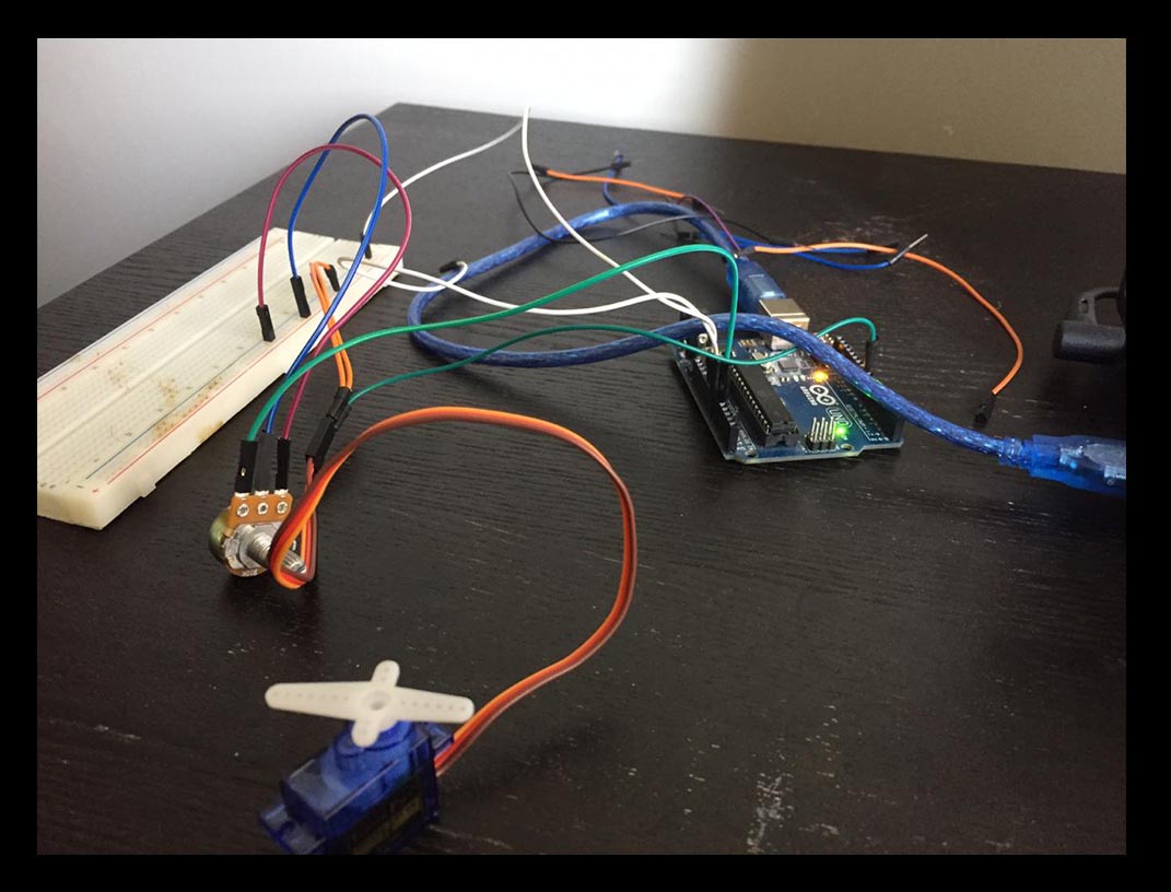
Working with Arduino kit
1- Knob test:
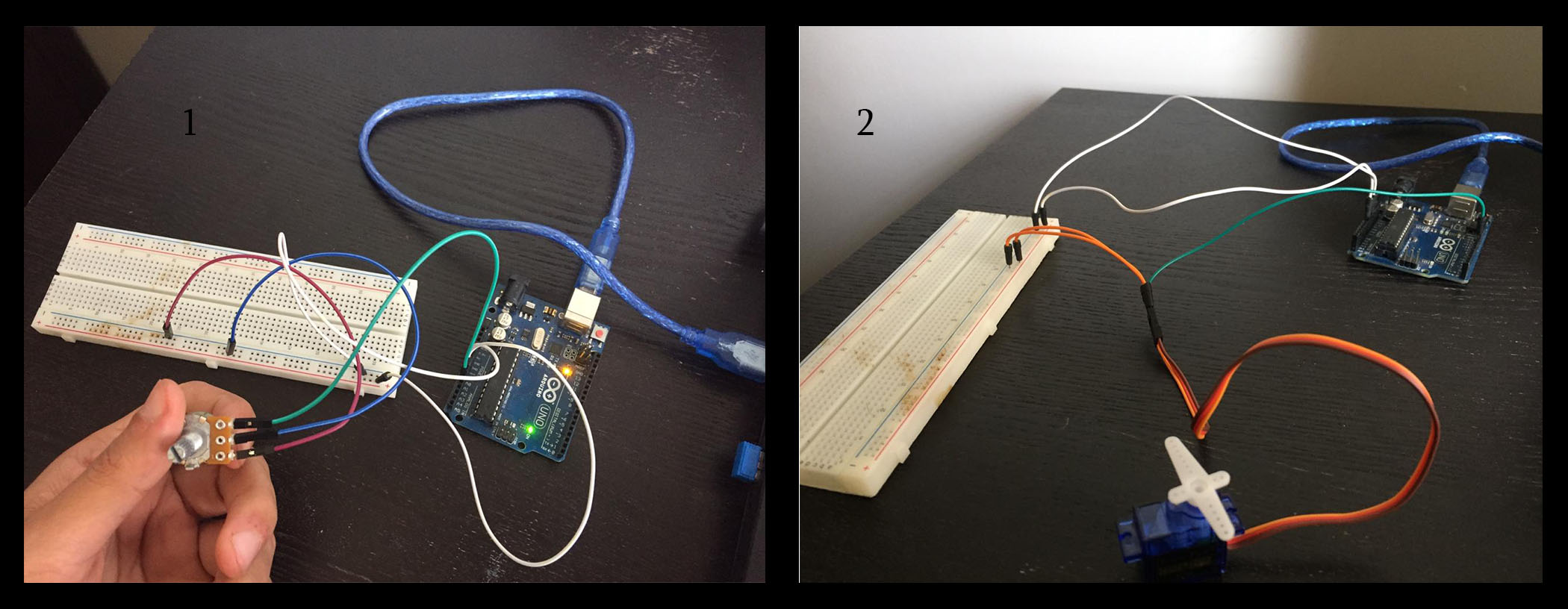
1- I have connected the _Potentiometers’s pin into wires in order to connect it to the power supply in the arduino pin (A0) and the other to pins to the (+) and (-) in the breadboard.
2- i have connected the servo-moter’s pins into the wires in order to connect the motor to the power supply as shown.
Arduino Code
        #include <Servo.h>

        Servo myservo;  // create servo object to control a servo

        int potpin = 0;  // analog pin used to connect the potentiometer
        int val;    // variable to read the value from the analog pin

        void setup() {
          myservo.attach(9);  // attaches the servo on pin 9 to the servo object
        }

        void loop() {
          val = analogRead(potpin);            // reads the value of the potentiometer (value between 0 and 1023)
          val = map(val, 0, 1023, 0, 180);     // scale it to use it with the servo (value between 0 and 180)
          myservo.write(val);                  // sets the servo position according to the scaled value
          delay(15);                           // waits for the servo to get there
        }
TinkerCad Simulation
HERO SHOT!
Servo-Motor
Work with Board :
Make a board with Servo controlled by Arduino’s codes .
for this week i wanted to make a servo motor board to test the servo rotation for the final project :
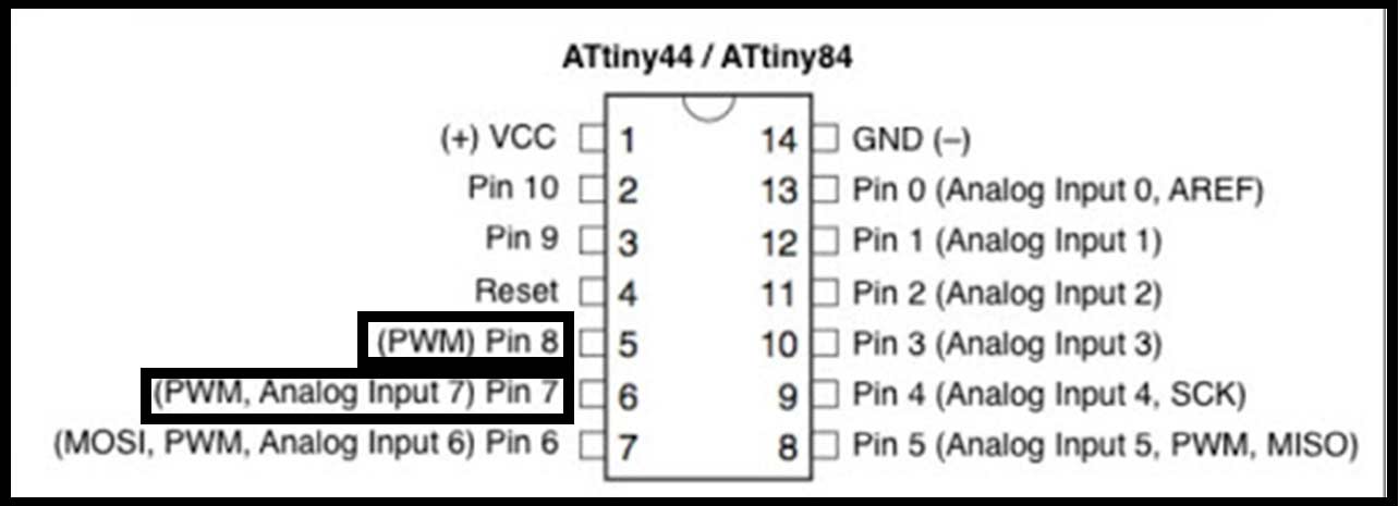
MicroController:
ATtiny 44 :
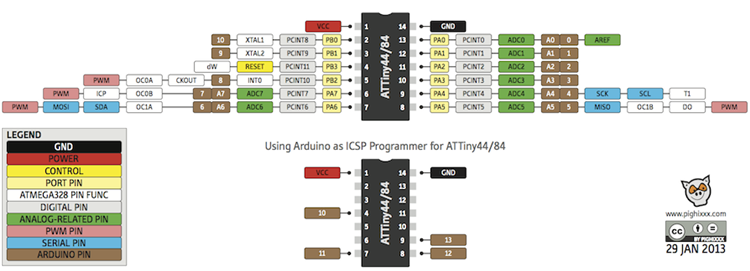
Connect the servo signal pin to PWM pin with ATtiny 44 as shown below:
The other PWM pins it should be connected to the ISP pins :
SCK, MISO, MOSI,
Work with Eagle
Files
Components
| Q | Component |
|---|---|
| 1 | ATtiny 44 |
| 1 | Xtal |
| 1 | resistor 0k |
| 1 | cap 1uf |
| 1 | pin header 3*2 |
| 1 | pin header 2*2 |
| 1 | resistor 10k |
The servo signal pin connected to PB2 pwm pin as shown below
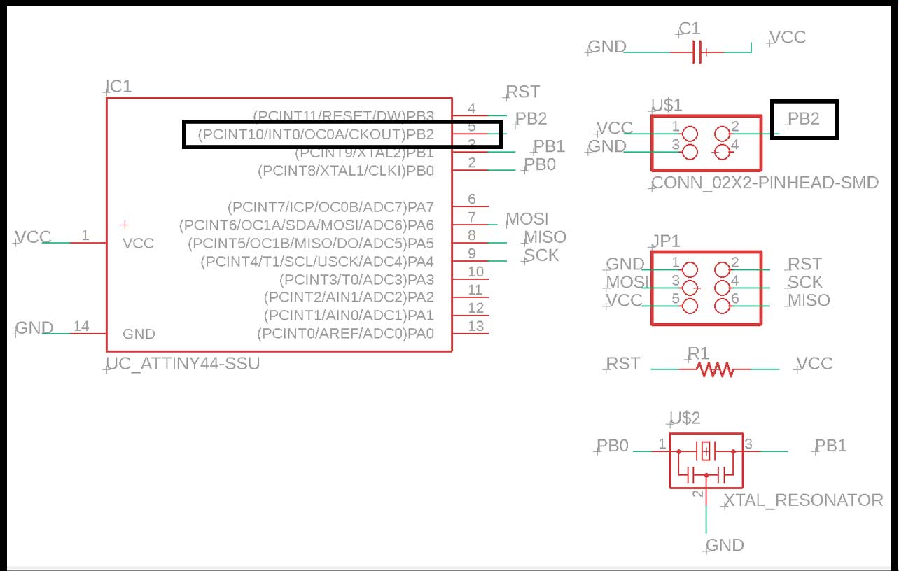
Then export the schematic to board design
Check Week 7 to know how to design the board.

Working with mods
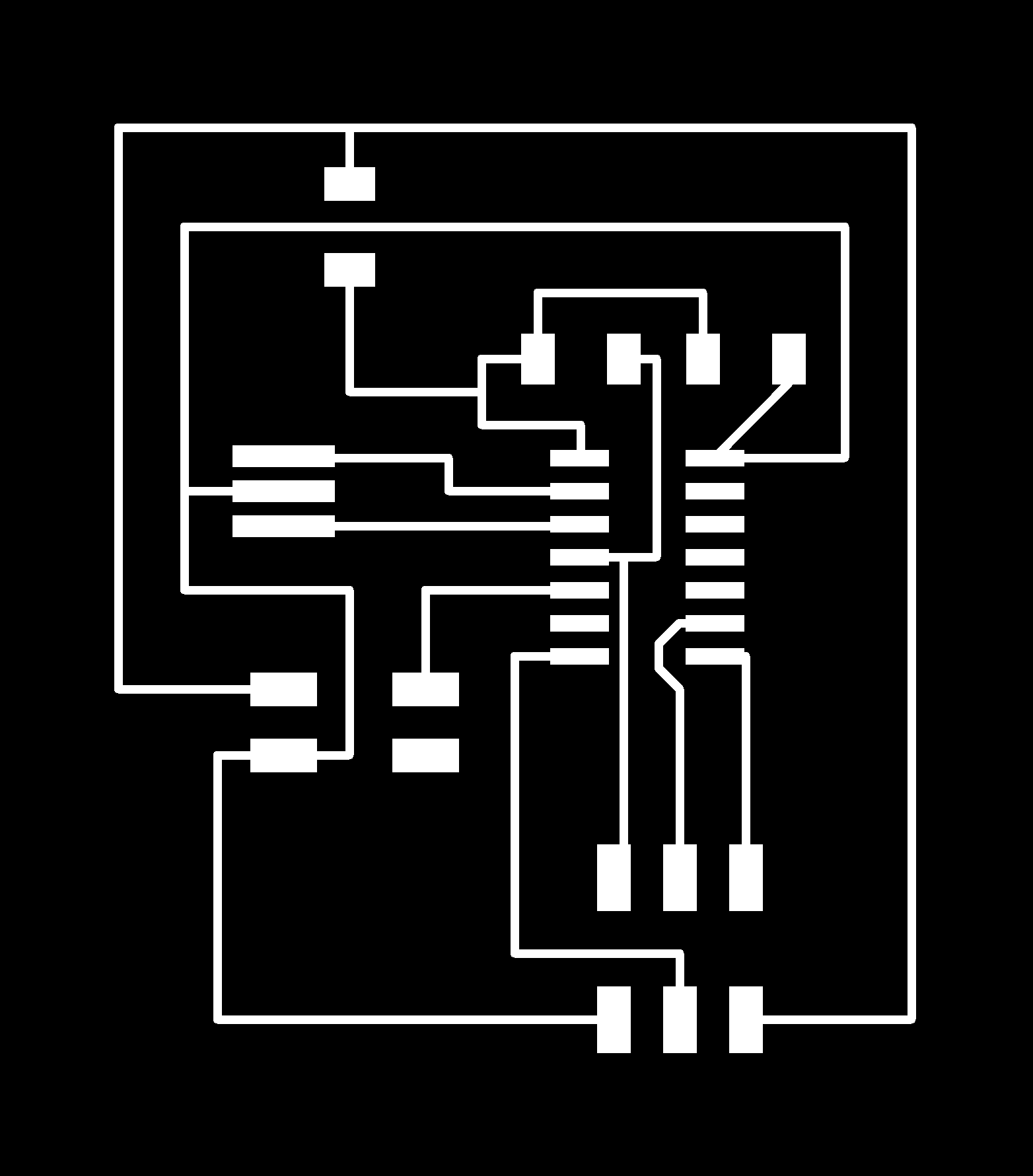
First transform the traces ‘png’ file to ‘RML’ as shown bellow
Traces :

Step 1 : select the png file
Step 2 : from PCB details choose mill traces (1/64).
Step 3 : from mill raster 2D click “calculate”.
Interior

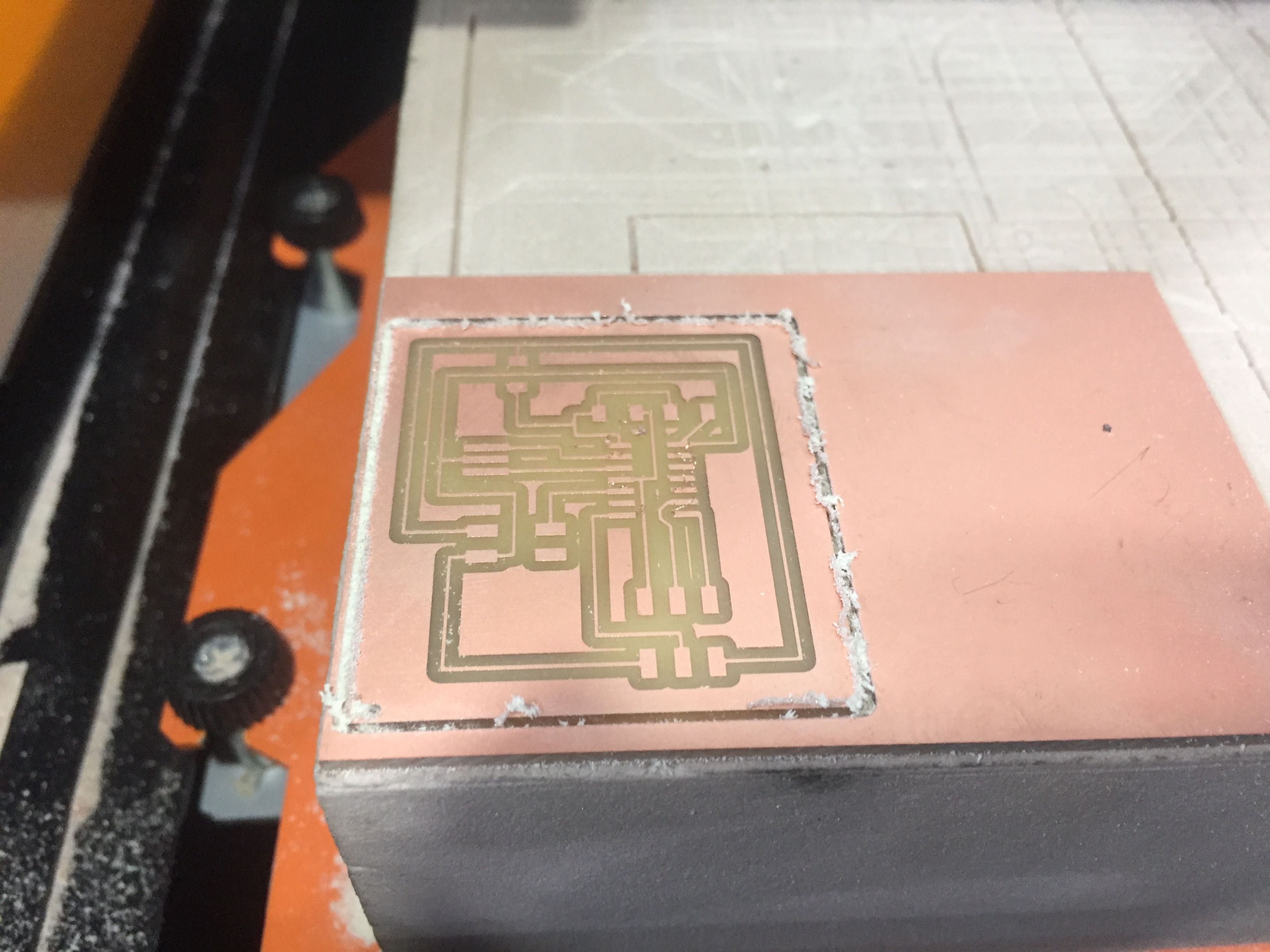
Milling the board
Step 1 : Place the PCB inside the Machine .
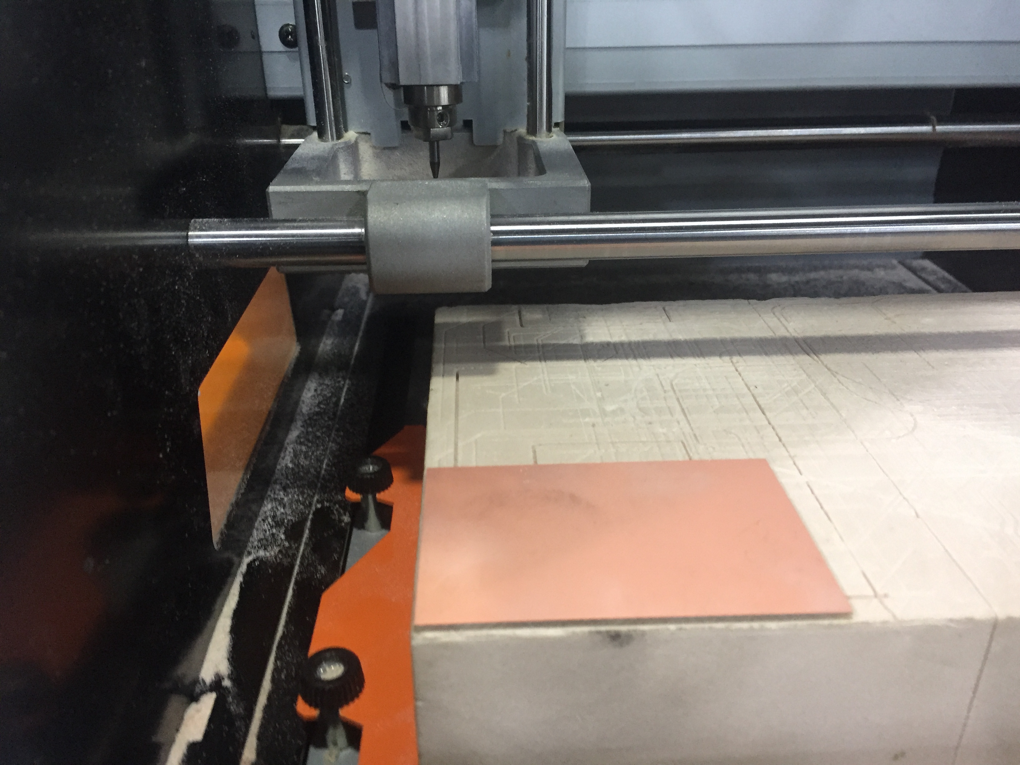
Step 2 : place the bit 1/64 then make the x,y,z axis to zero by moving the bit with the arrows.
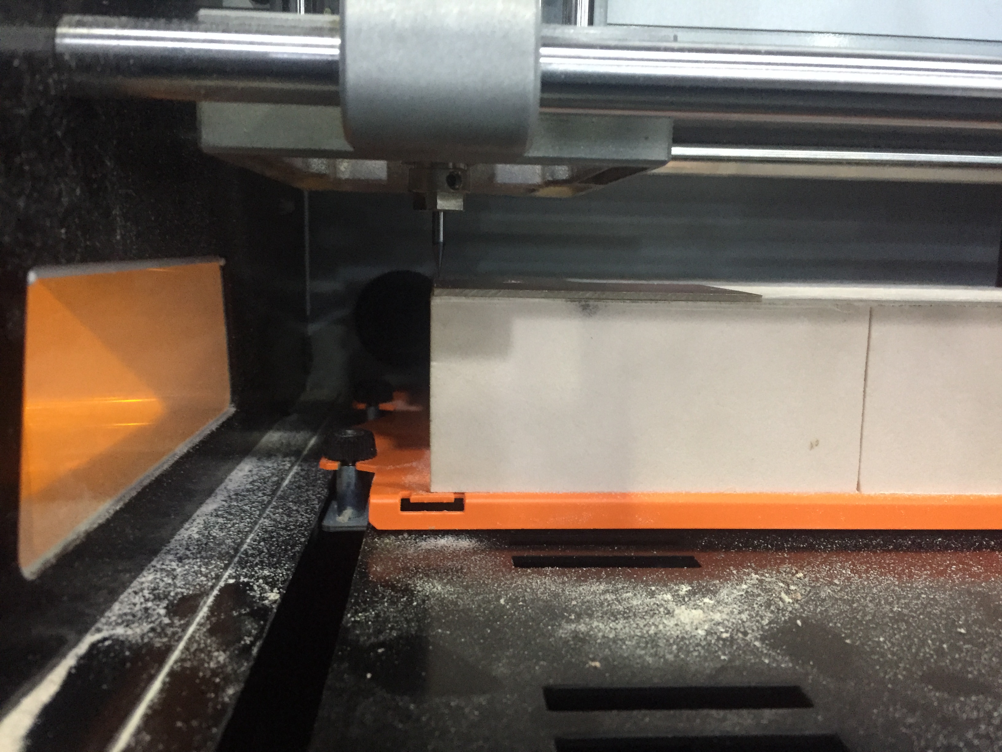
Step 3 : After zero the z axis as shown below move the bit 1mm up to keep the bit safe from broken once the bit start rotating.
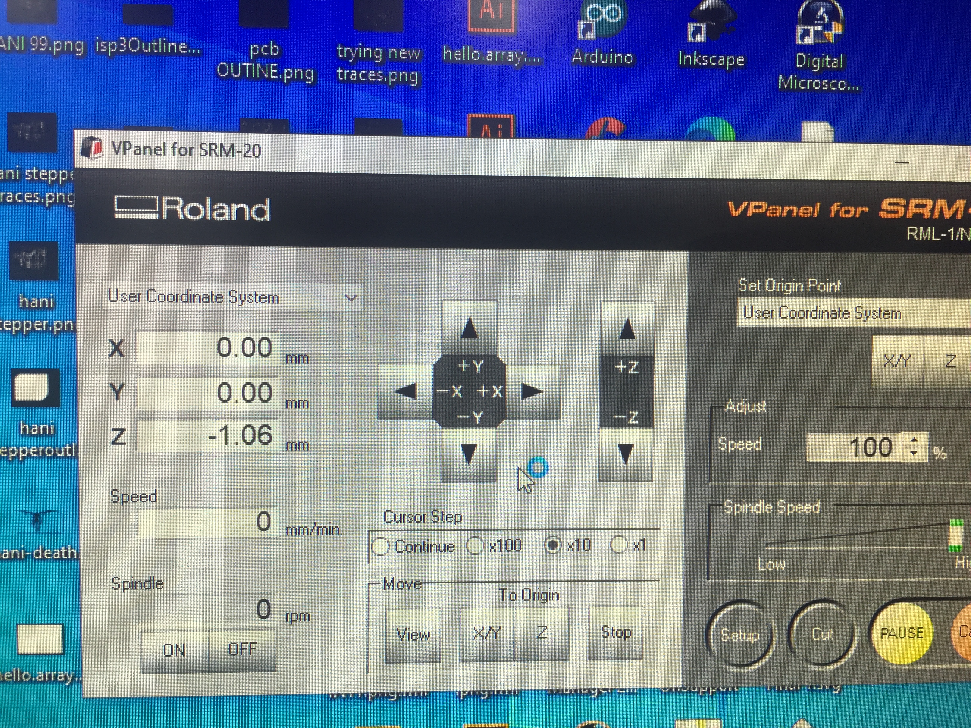
Step 4 : then upload the rml file to start mill.
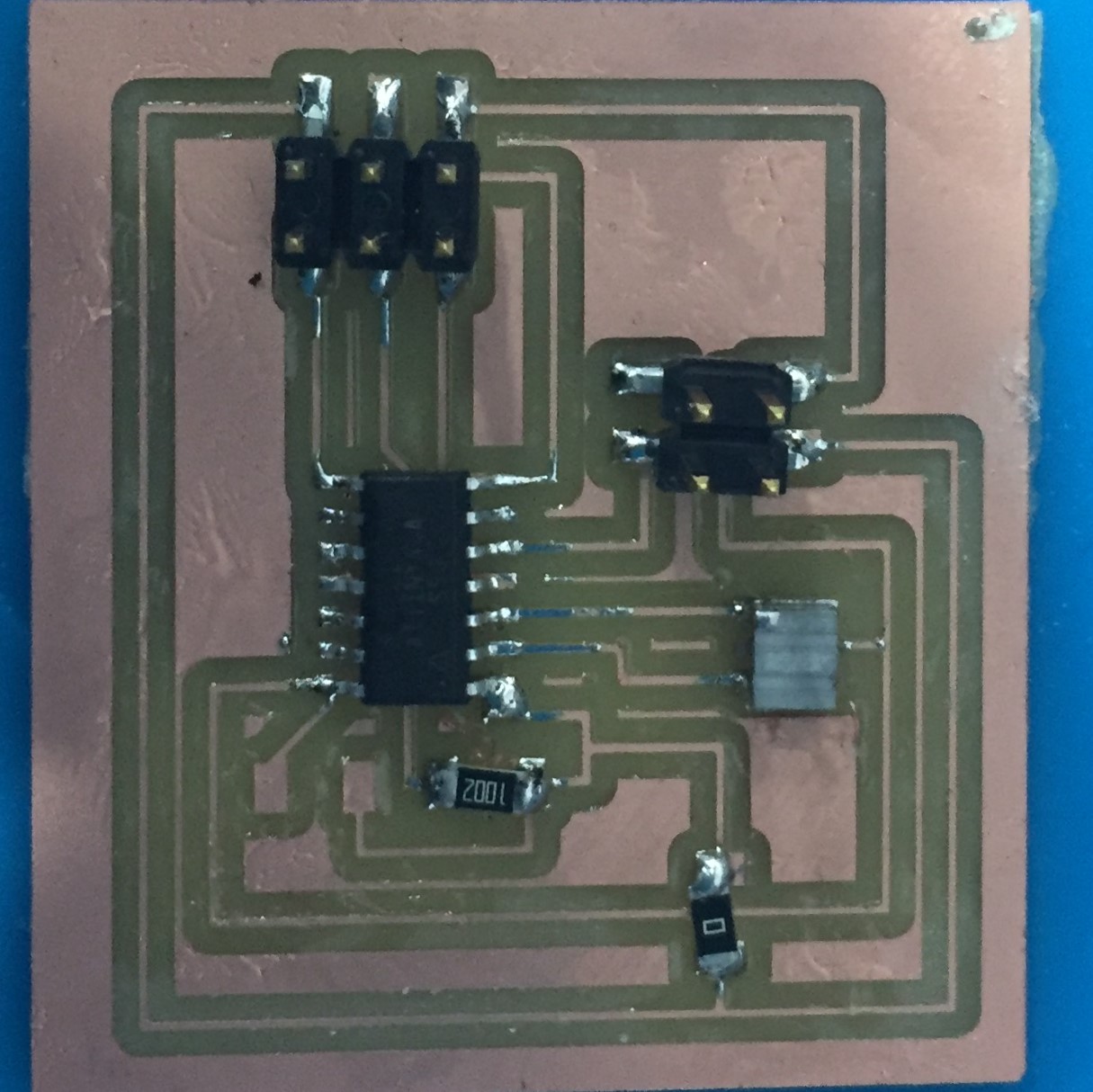
Soldering the Components
Programming
Connect the ISP to the board to upload the code below
Code
    #include <Servo.h>

    Servo myservo;  // create servo object to control a servo
    // twelve servo objects can be created on most boards

    int pos = 0;    // variable to store the servo position

    void setup() {
      myservo.attach(2);  // attaches the servo on pin 9 to the servo object
    }

    void loop() {
      for (pos = 0; pos <= 180; pos += 1) { // goes from 0 degrees to 180 degrees
        // in steps of 1 degree
        myservo.write(pos);              // tell servo to go to position in variable 'pos'
        delay(15);                       // waits 15ms for the servo to reach the position
      }
      for (pos = 180; pos >= 0; pos -= 1) { // goes from 180 degrees to 0 degrees
        myservo.write(pos);              // tell servo to go to position in variable 'pos'
        delay(15);                       // waits 15ms for the servo to reach the position
      }
    }
Oops
After Uploading the code the Servo dose not rotate 180 and i could not figure out what is going on but it seems that the servo does not work with ATtiny 44 specifically because i happened also to my colleague.
For the final project i connected the Servo to the ATmega and it worked perfectly as shown below :
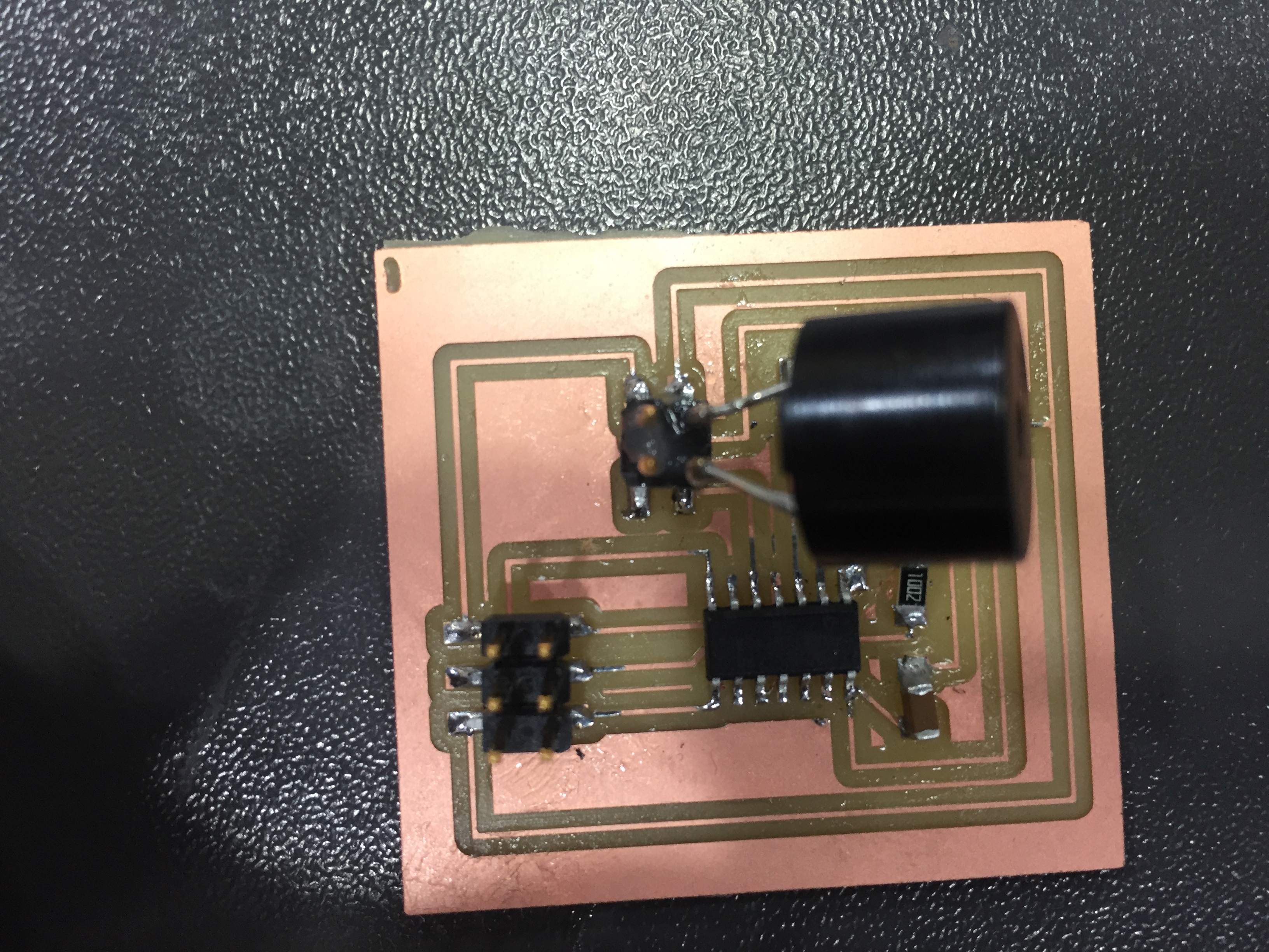
Buzzer

I connected The buzzer instead of the servo and it worked
Code
    void setup() {
      // initialize digital pin LED_BUILTIN as an output.
      pinMode(2, OUTPUT);
    }

    // the loop function runs over and over again forever
    void loop() {
      digitalWrite(2, HIGH);   // turn the LED on (HIGH is the voltage level)
      delay(1000);                       // wait for a second
      digitalWrite(2, LOW);    // turn the LED off by making the voltage LOW
      delay(1000);                       // wait for a second
    }