13. Interface and application programming
This week I worked on defining my final project idea and started to getting used to the documentation process.
Group Assignment:
We have done Online workshop to discuss the difference between multiple applications such as Python, processing, MIT app inventor and Firefly
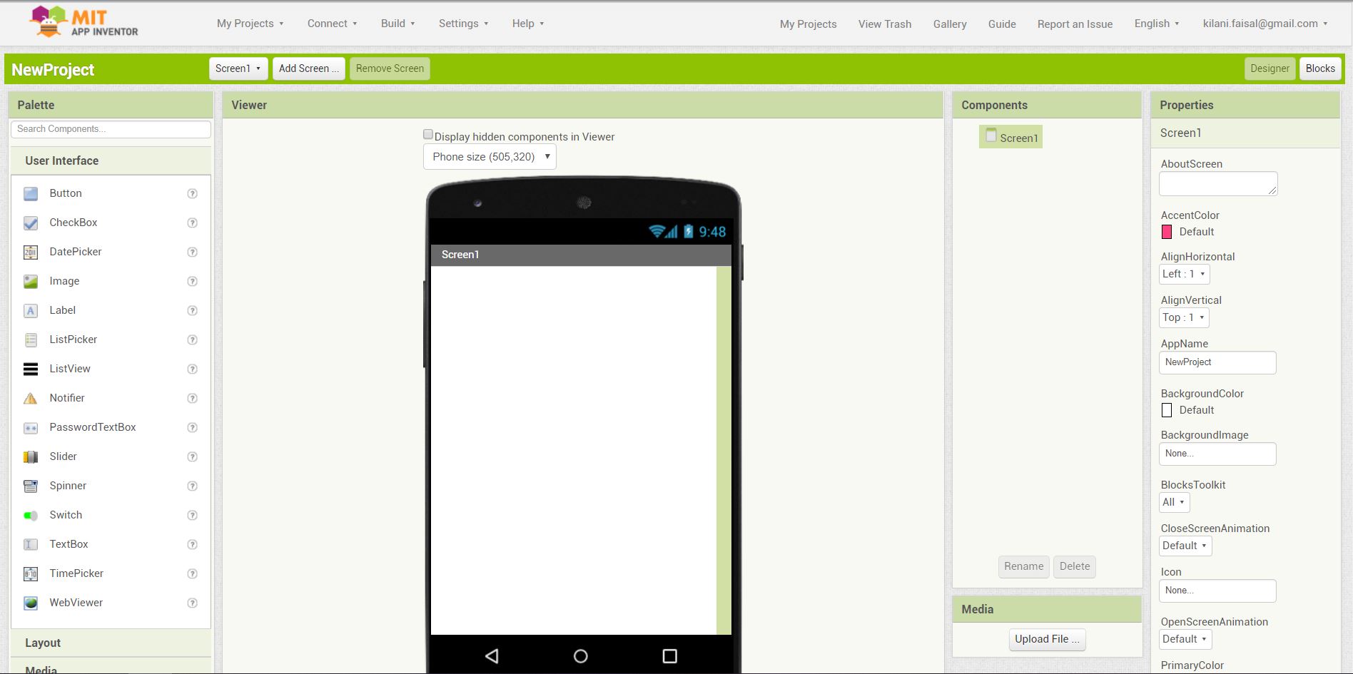
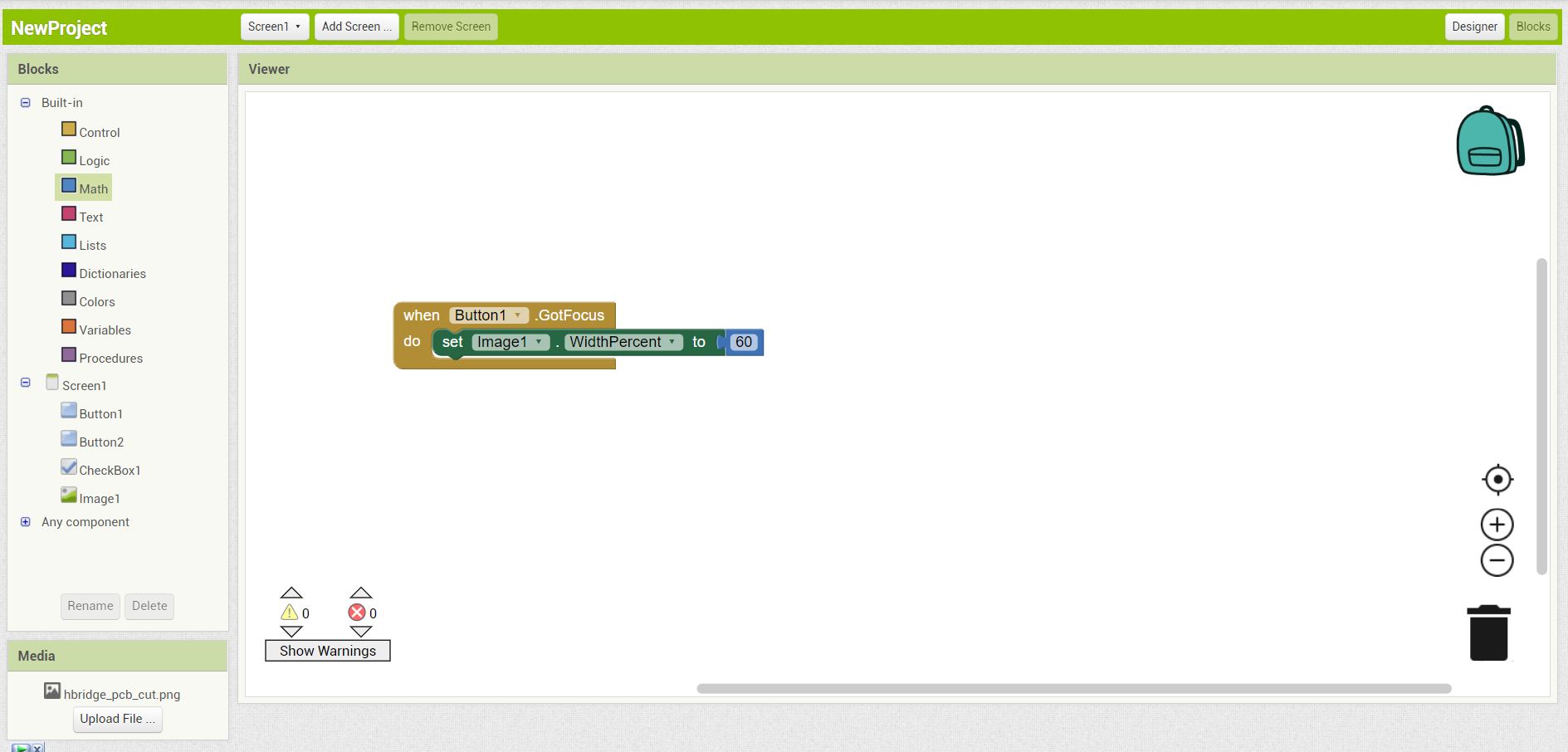
1- It has an easy interface, where you can add element by dragging them into the phone screen from the left side, first we see the designer UI, when we start the program.
2- There are many tools to add and customize, and we can use the electronics of the phone; like camera, microphone and Bluetooth, and utilize them to certain jobs.
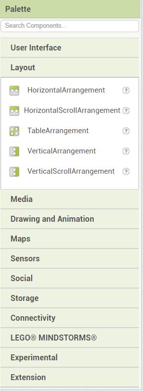
3- When adding elements to the program, we have the option to change the properties like text, scale, font.
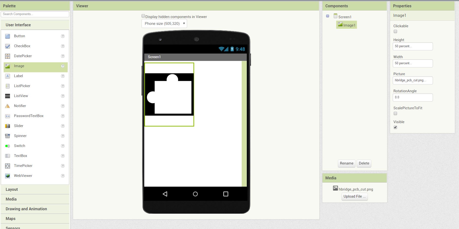
4- Also change the shapes and color of the added elements.
5- In the block UI, we can program the app just by adding blocks to each-other to preform an action.
Individual Assignment
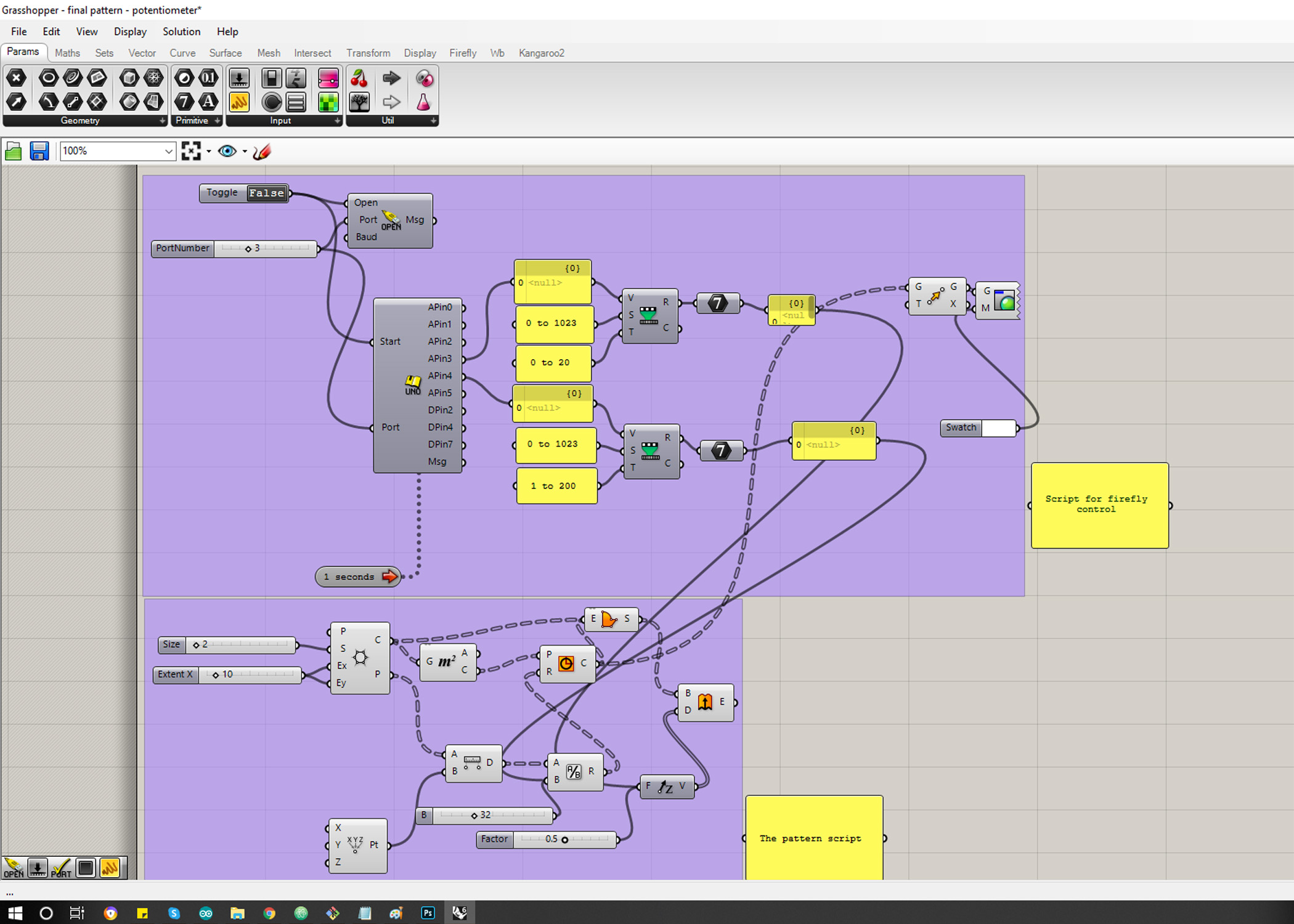
I have done a similar pattern for my final project and control the Geometries using Firefly grasshopper and Arduino, i read the data from the temperature sensor and controled LED.
First: the Apps i have used
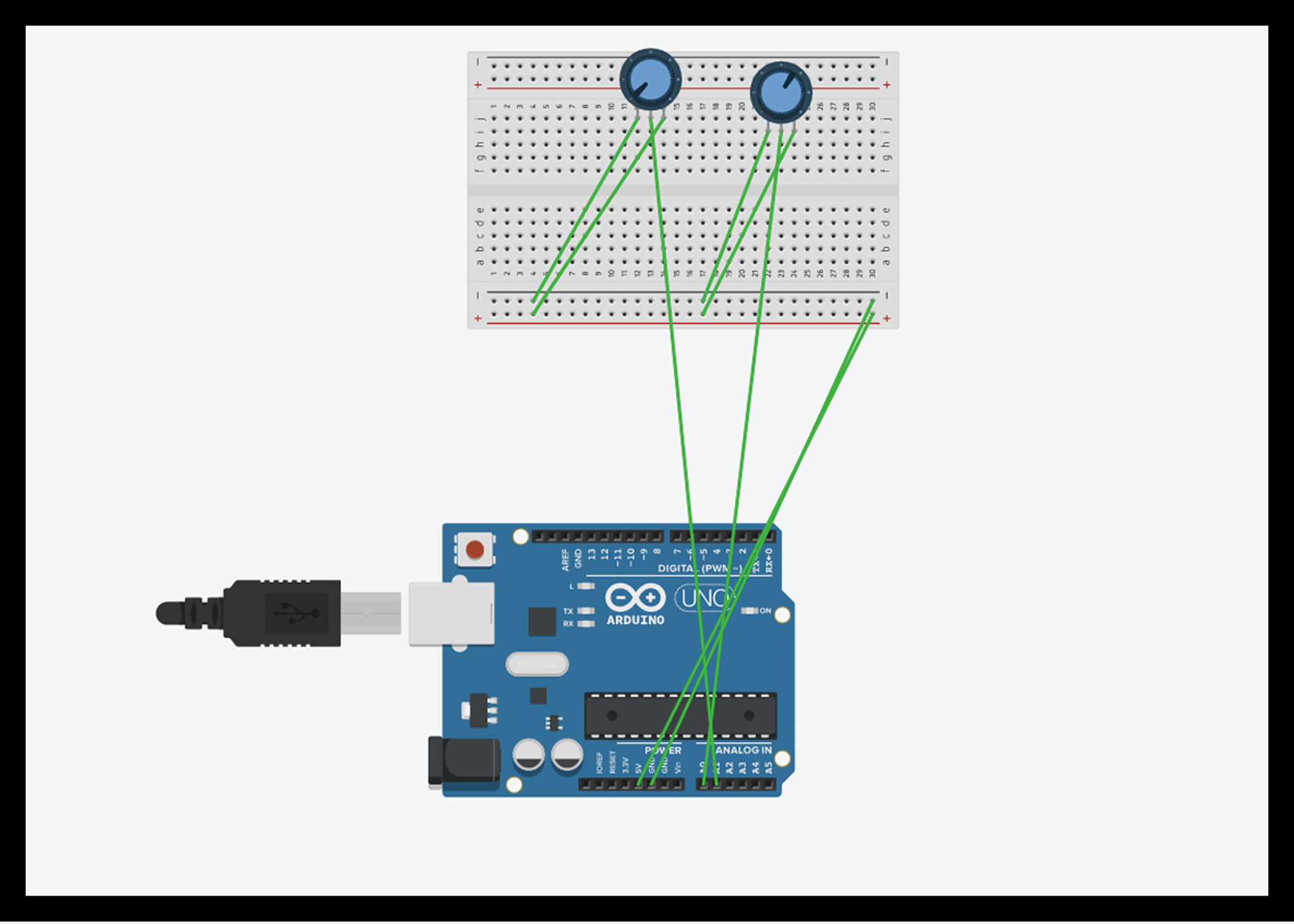
The Equipments
| Item | Quantity |
|---|---|
| Arduino UNO | 1 |
| BreadBoard | 1 |
| Wires | 10 |
| Potentiometer | 2 |
Files
TinkerCad connection Simulation :
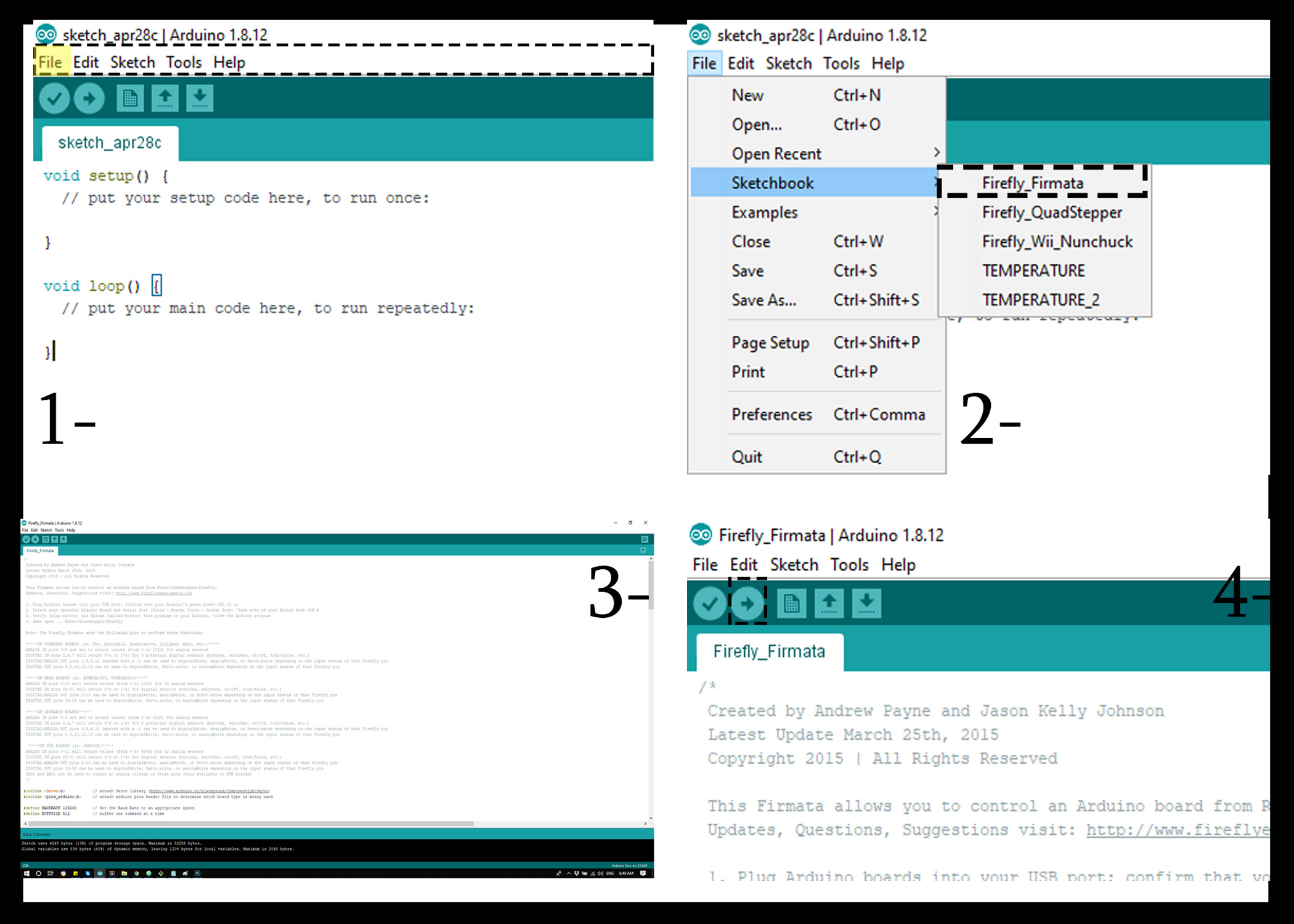
First : Work with Arduino !
Step 1 : Open Arduino app
Step 2 : Go to file - Sketchbook - choose (firefly firmata).
Step 3 : Then press on Upload button the get the code ready for the next step.
Step 4 : change the last part of the code as following ” only if the arduino version is the latest version “
      #if defined(__SAM3X8E__)

      void WriteToDAC(int _pin, int _value){

        if(_pin == 0) analogWrite(DAC0, _value);
        else if (_pin == 1) analogWrite(DAC1, _value);

      }

      #endif
Change it to this :
      void WriteToDAC(int _pin, int _value){
        #if defined(__SAM3X8E__)

        if(_pin == 0) analogWrite(DAC0, _value);
        else if (_pin == 1) analogWrite(DAC1, _value);

      }
.
      /*
       Created by Andrew Payne and Jason Kelly Johnson
       Latest Update March 25th, 2015
       Copyright 2015 | All Rights Reserved

       This Firmata allows you to control an Arduino board from Rhino/Grasshopper/Firefly.
       Updates, Questions, Suggestions visit: http://www.fireflyexperiments.com

       1. Plug Arduino boards into your USB port; confirm that your Arduino's green power LED in on
       2. Select your specific Arduino Board and Serial Port (Tools > Board; Tools > Serial Port) *Take note of your Serial Port COM #
       3. Verify (play button) and Upload (upload button) this program to your Arduino, close the Arduino program
       4. then open ... Rhino/Grasshopper/Firefly

       Note: The Firefly Firmata sets the following pins to perform these functions:

       *****ON STANDARD BOARDS (ie. Uno, Diecimila, Duemilanove, Lillypad, Mini, etc.)*****
       ANALOG IN pins 0-5 are set to return values (from 0 to 1023) for analog sensors
       DIGITAL IN pins 2,4,7 will return 0's or 1's; for 3 potential digital sensors (buttons, switches, on/off, true/false, etc.)
       DIGITAL/ANALOG OUT pins 3,5,6,11 (marked with a ~) can be used to digitalWrite, analogWrite, or Servo.write depending on the input status of that Firefly pin
       DIGITAL OUT pins 8,9,10,12,13 can be used to digitalWrite, Servo.write, or analogWrite depending on the input status of that Firefly pin

       *****ON MEGA BOARDS (ie. ATMEGA1280, ATMEGA2560)*****
       ANALOG IN pins 0-15 will return values (from 0 to 1023) for 16 analog sensors
       DIGITAL IN pins 22-31 will return 0's or 1's; for digital sensors (buttons, switches, on/off, true/false, etc.)
       DIGITAL/ANALOG OUT pins 2-13 can be used to digitalWrite, analogWrite, or Servo.write depending on the input status of that Firefly pin
       DIGITAL OUT pins 32-53 can be used to digitalWrite, Servo.write, or analogWrite depending on the input status of that Firefly pin

       *****ON LEONARDO BOARDS*****
       ANALOG IN pins 0-5 are set to return values (from 0 to 1023) for analog sensors
       DIGITAL IN pins 2,4,7 will return 0's or 1's; for 3 potential digital sensors (buttons, switches, on/off, true/false, etc.)
       DIGITAL/ANALOG OUT pins 3,5,6,11 (marked with a ~) can be used to digitalWrite, analogWrite, or Servo.write depending on the input status of that Firefly pin
       DIGITAL OUT pins 8,9,10,12,13 can be used to digitalWrite, Servo.write, or analogWrite depending on the input status of that Firefly pin

        *****ON DUE BOARDS (ie. SAM3X8E)*****
       ANALOG IN pins 0-11 will return values (from 0 to 4095) for 12 analog sensors
       DIGITAL IN pins 22-31 will return 0's or 1's; for digital sensors (buttons, switches, on/off, true/false, etc.)
       DIGITAL/ANALOG OUT pins 2-13 can be used to digitalWrite, analogWrite, or Servo.write depending on the input status of that Firefly pin
       DIGITAL OUT pins 32-53 can be used to digitalWrite, Servo.write, or analogWrite depending on the input status of that Firefly pin
       DAC0 and DAC1 can be used to output an analog voltage on those pins (only available on DUE boards)
       */

      #include <Servo.h>            // attach Servo library (http://www.arduino.cc/playground/ComponentLib/Servo)
      #include <pins_arduino.h>     // attach arduino pins header file to determine which board type is being used

      #define BAUDRATE 115200       // Set the Baud Rate to an appropriate speed
      #define BUFFSIZE 512          // buffer one command at a time

      /*==============================================================================
       * GLOBAL VARIABLES
       *============================================================================*/

      char buffer[BUFFSIZE];        // declare buffer
      uint8_t bufferidx = 0;        // a type of unsigned integer of length 8 bits
      char *parseptr;
      char buffidx;

      int counter = 0;
      int numcycles = 1000;

      #if defined(__AVR_ATmega328P__) || defined(__AVR_ATmega168__)                                                // declare variables for STANDARD boards
        Servo Servo13, Servo12, Servo11, Servo10, Servo9, Servo8, Servo6, Servo5, Servo3;
        Servo SERVO_CONFIG[] = {Servo13, Servo12, Servo11, Servo10, Servo9, Servo8, Servo6, Servo5, Servo3};       // declare array of Servo objects
        int WRITE_PIN_CONFIG[] = {13,12,11,10,9,8,6,5,3};
        int READ_APIN_CONFIG[] = {0,1,2,3,4,5};
        int READ_DPIN_CONFIG[] = {2,4,7};
      #endif

      #if defined(__AVR_ATmega32U4__) || defined(__AVR_ATmega16U4__)                                               // declare variables for LEONARDO board
        Servo Servo13, Servo12, Servo11, Servo10, Servo9, Servo8, Servo6, Servo5, Servo3;
        Servo SERVO_CONFIG[] = {Servo13, Servo12, Servo11, Servo10, Servo9, Servo8, Servo6, Servo5, Servo3};       // declare array of Servo objects
        int WRITE_PIN_CONFIG[] = {13,12,11,10,9,8,6,5,3};
        int READ_APIN_CONFIG[] = {0,1,2,3,4,5};
        int READ_DPIN_CONFIG[] = {2,4,7};
      #endif

      #if defined(__AVR_ATmega1280__) || defined(__AVR_ATmega2560__)                        // declare variables for MEGA boards
        Servo Servo2, Servo3, Servo4, Servo5, Servo6, Servo7, Servo8, Servo9, Servo10, Servo11, Servo12, Servo13, Servo32, Servo33, Servo34, Servo35, Servo36, Servo37, Servo38, Servo39, Servo40, Servo41, Servo42, Servo43, Servo44, Servo45, Servo46, Servo47, Servo48, Servo49, Servo50, Servo51, Servo52, Servo53;
        Servo SERVO_CONFIG[] = {Servo2, Servo3, Servo4, Servo5, Servo6, Servo7, Servo8, Servo9, Servo10, Servo11, Servo12, Servo13, Servo32, Servo33, Servo34, Servo35, Servo36, Servo37, Servo38, Servo39, Servo40, Servo41, Servo42, Servo43, Servo44, Servo45, Servo46, Servo47, Servo48, Servo49, Servo50, Servo51, Servo52, Servo53};  // declare array of Servo objects
        int WRITE_PIN_CONFIG[] = {2,3,4,5,6,7,8,9,10,11,12,13,32,33,34,35,36,37,38,39,40,41,42,43,44,45,46,47,48,49,50,51,52,53};
        int READ_APIN_CONFIG[] = {0,1,2,3,4,5,6,7,8,9,10,11,12,13,14,15};
        int READ_DPIN_CONFIG[] = {22,23,24,25,26,27,28,29,30,31};
      #endif

      #if defined(__SAM3X8E__)                 // declare variables for DUE boards
        Servo FDAC0, FDAC1, Servo2, Servo3, Servo4, Servo5, Servo6, Servo7, Servo8, Servo9, Servo10, Servo11, Servo12, Servo13, Servo32, Servo33, Servo34, Servo35, Servo36, Servo37, Servo38, Servo39, Servo40, Servo41, Servo42, Servo43, Servo44, Servo45, Servo46, Servo47, Servo48, Servo49, Servo50, Servo51, Servo52, Servo53;
        Servo SERVO_CONFIG[] = {FDAC0, FDAC1, Servo2, Servo3, Servo4, Servo5, Servo6, Servo7, Servo8, Servo9, Servo10, Servo11, Servo12, Servo13, Servo32, Servo33, Servo34, Servo35, Servo36, Servo37, Servo38, Servo39, Servo40, Servo41, Servo42, Servo43, Servo44, Servo45, Servo46, Servo47, Servo48, Servo49, Servo50, Servo51, Servo52, Servo53};  // declare array of Servo objects
        int WRITE_PIN_CONFIG[] = {0,1,2,3,4,5,6,7,8,9,10,11,12,13,32,33,34,35,36,37,38,39,40,41,42,43,44,45,46,47,48,49,50,51,52,53}; //Note: first two values correspond to the DAC pins
        int READ_APIN_CONFIG[] = {0,1,2,3,4,5,6,7,8,9,10,11};
        int READ_DPIN_CONFIG[] = {22,23,24,25,26,27,28,29,30,31};
      #endif

      /*==============================================================================
       * SETUP() This code runs once
       *============================================================================*/
      void setup()
      {
        Init();                       //set initial pinmodes
        Serial.begin(BAUDRATE);       // Start Serial communication
        #if defined(__SAM3X8E__)      //if the connected board is an Arduino DUE
          analogReadResolution(12);   //Set the analog read resolution to 12 bits (acceptable values between 1-32 bits).  This is only for DUE boards
          analogWriteResolution(12);  // Set the analog write resolution to 12 bits (acceptable values between 1-32 bits).  This is only for DUE boards
        #endif
      }

      /*==============================================================================
       * LOOP() This code loops
       *============================================================================*/
      void loop()
      {
        if(Serial){
          ReadSerial();                       // read and parse string from serial port and write to pins
          if (counter >= numcycles){          // Wait every nth loop
            ReadInputs();                     // get input data and print data to the serial port
            counter = 0;                      // reset the counter
          }
          counter ++;                         // increment the writecounter
        }
      }

      /*==============================================================================
       * FUNCTIONS()
       *============================================================================*/

      /*
      * Initializes the digital pins which will be used as inputs
      */
      void Init(){
        int len = sizeof(READ_DPIN_CONFIG)/sizeof(READ_DPIN_CONFIG[0]); //get the size of the array
        for(int i = 0; i < len; i++){
          pinMode(READ_DPIN_CONFIG[i], INPUT);
        }
      }

      /*
      * Reads the incoming ADC or digital values from the corresponding analog and digital input
      * pins and prints the value to the serial port as a formatted commma separated string
      */
      void ReadInputs(){
        int len = sizeof(READ_APIN_CONFIG)/sizeof(READ_APIN_CONFIG[0]); //get the size of the array
        for(int i = 0; i < len; i++){
          int val = analogRead(READ_APIN_CONFIG[i]);  //read value from analog pins
          Serial.print(val); Serial.print(",");
        }
        len = sizeof(READ_DPIN_CONFIG)/sizeof(READ_DPIN_CONFIG[0]); //get the size of the array
        for(int i = 0; i < len; i++){
          int val = digitalRead(READ_DPIN_CONFIG[i]); //read value from digital pins
          Serial.print(val); Serial.print(",");
        }
        Serial.println("eol");  //end of line marker
      }

      /*
      * Retrieve the latest incoming serial value and split the string at the comma delimeter.
      * When a comma is found, the value is offloaded to a temporary variable and written
      * to the corresponding digital pin.
      */
      void ReadSerial(){
        char c;    // holds one character from the serial port
        if (Serial.available()) {
          c = Serial.read();         // read one character
          buffer[bufferidx] = c;     // add to buffer
          if (c == '\n') {
            buffer[bufferidx+1] = 0; // terminate it
            parseptr = buffer;       // offload the buffer into temp variable
            int len = sizeof(WRITE_PIN_CONFIG)/sizeof(WRITE_PIN_CONFIG[0]); //get the size of the array
            for(int i = 0; i < len; i++){
              //parse all incoming values and assign them to the appropriate variable
              int val = parsedecimal(parseptr);       // parse the incoming number
              if(i != len - 1) parseptr = strchr(parseptr, ',')+1;   // move past the ","
              WriteToPin(WRITE_PIN_CONFIG[i], val, SERVO_CONFIG[i]);         //send value out to pin on arduino board
            }
            bufferidx = 0;                             // reset the buffer for the next read
            return;                                    // return so that we don't trigger the index increment below
          }                                            // didn't get newline, need to read more from the buffer
          bufferidx++;                                 // increment the index for the next character
          if (bufferidx == BUFFSIZE-1) bufferidx = 0;  // if we get to the end of the buffer reset for safety
        }
      }

      /*
      * Send the incoming value to the appropriate pin using pre-defined logic (ie. digital, analog, or servo)
      */
      void WriteToPin(int _pin, int _value, Servo _servo){
        if (_value >= 10000 && _value < 20000)            // check if value should be used for Digital Write (HIGH/LOW)
        {
          if (_servo.attached()) _servo.detach();         // detach servo is one is attached to pin
          pinMode(_pin, OUTPUT);
          _value -= 10000;                                // subtract 10,000 from the value sent from Grasshopper
          if (_value == 1) digitalWrite(_pin, HIGH);
          else digitalWrite(_pin, LOW);
        }
        else if (_value >= 20000 && _value < 30000)       // check if value should be used for Analog Write (0-255)
        {
          if (_servo.attached()) _servo.detach();         // detach servo is one is attached to pin
          pinMode(_pin, OUTPUT);
          _value -= 20000;                                // subtract 20,000 from the value sent from Grasshopper
          analogWrite(_pin, _value);
        }
        else if (_value >= 30000 && _value < 40000)       // check if value should be used for Servo Write (0-180)
        {
          _value -= 30000;                                // subtract 30,000 from the value sent from Grasshopper
          if (!_servo.attached())_servo.attach(_pin);     // attaches a Servo to the PWM pin (180 degree standard servos)
          _servo.write(_value);
        }
        else if (_value >= 40000 && _value < 50000)       // check if value should be used for Analog Write (0-4096) for DACs
        {
          if (_servo.attached()) _servo.detach();         // detach servo is one is attached to pin
          pinMode(_pin, OUTPUT);
          _value -= 40000;                                // subtract 40,000 from the value sent from Grasshopper
          WriteToDAC(_pin, _value);
        }
      }

      /*
      * Parse a string value as a decimal
      */
      uint32_t parsedecimal(char *str){
        uint32_t d = 0;
        while (str[0] != 0) {
          if ((str[0] > '50') || (str[0] < '0'))
            return d;
          d *= 10;
          d += str[0] - '0';
          str++;
        }
        return d;
      }

      /*
      * Send the incoming value to the appropriate DAC for DUE boards.
      * Note: analogWrite resolution (default is 12 bits) is defined in the Setup function.
      */
        void WriteToDAC(int _pin, int _value){
           #if defined(__SAM3X8E__)

          if(_pin == 0) analogWrite(DAC0, _value);
          else if (_pin == 1) analogWrite(DAC1, _value);
          #endif

        }
Work with Grasshopper !
Step 1 : Open Rhino App.
Step 2 : Go to tools - choose Grasshopper.
Step 3 : From the tool bar choose Firefly.
Work with the Script
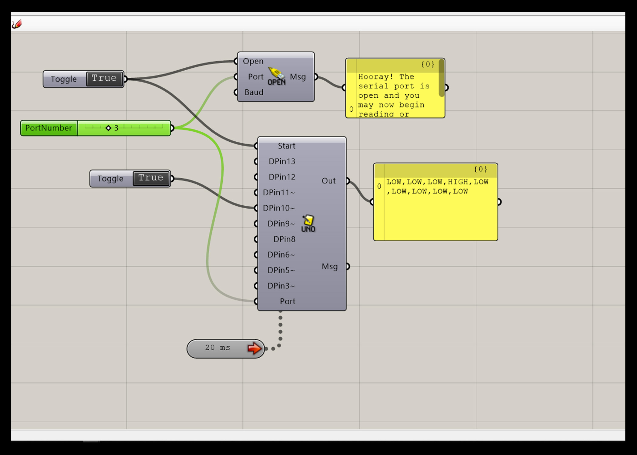
First test (LED):
The file :
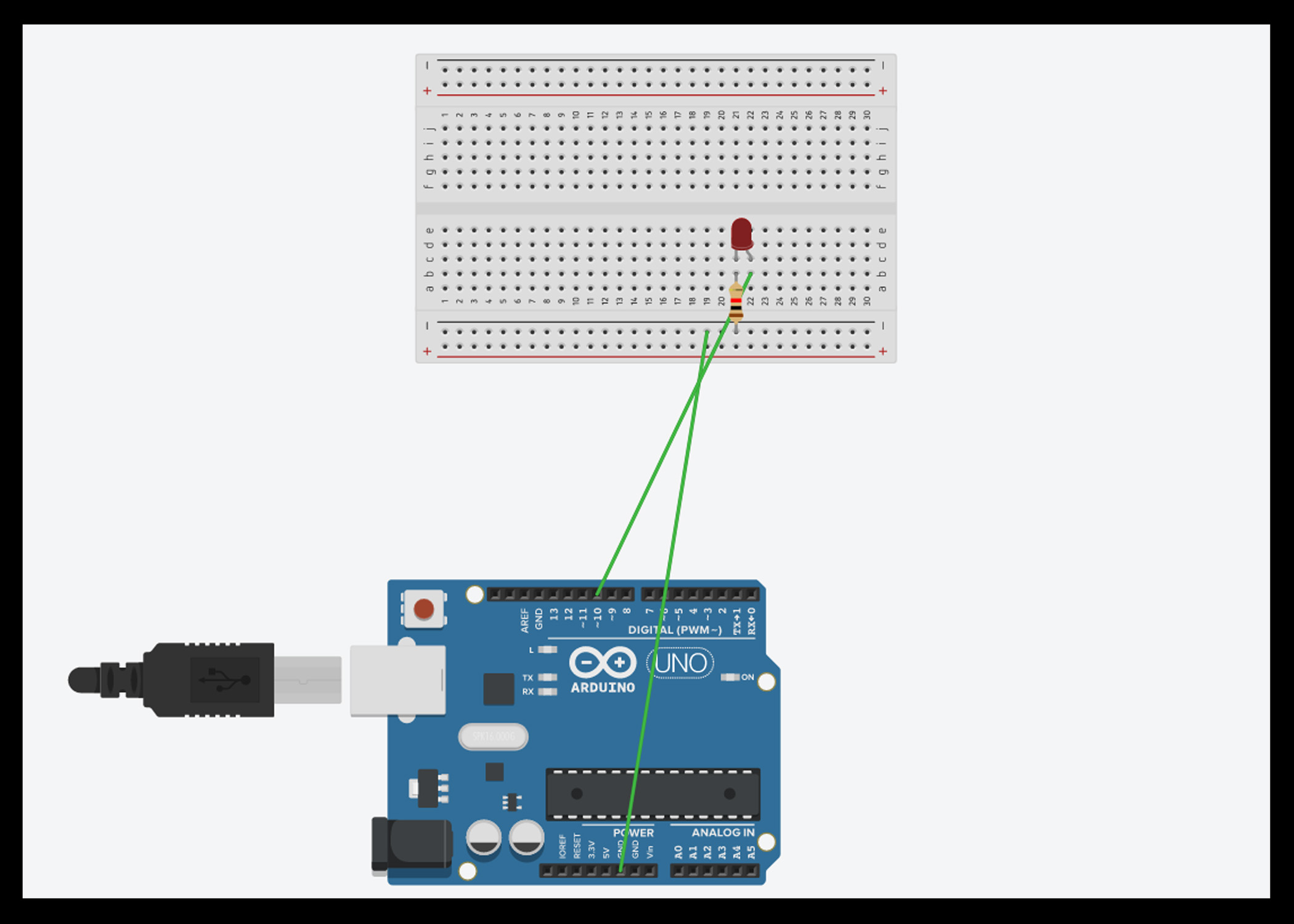
HERO SHOTS
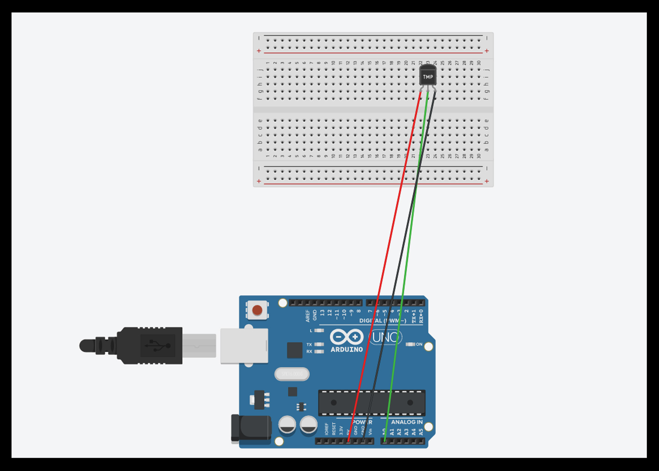
second test: Reading the data from the temperature sensor (lm35).
HERO SHOT_
1 - follow this tutorial below and edit it to get the fellow connection:
Hero shot !