7. Electronics design
This week Assignments! 
Group project
Use the test equipment in your lab to observe the operation of a microcontroller circuit board.
Individual project
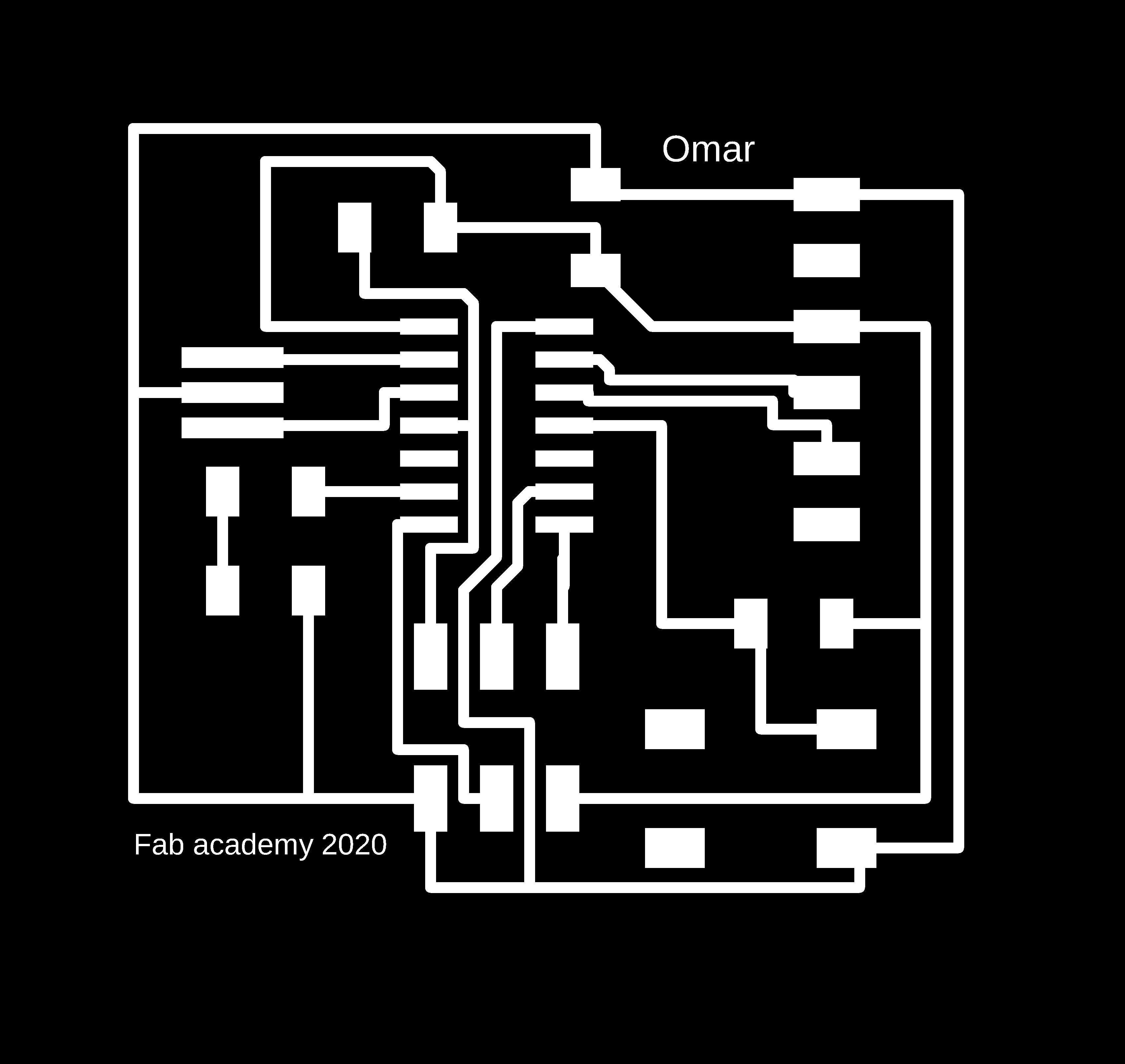
Redraw an echo hello-world board,
add (at least) a button and LED (with current-limiting resistor) check the design rules, make it, and test it extra credit: simulate its operation
Machine
The Machine that exists in Techworks Amman is:
-“ROLAND SRM-20”
Features - Loadable Workpiece Size: 8” x 6” x 2.8” Table Size: 9.14” x 6.17” Max Tool Size: 1/4” or 6mm.
Spindle Speed: 3000-7000 rpm.
- Tools: Milling bit 0,8 (1/32”), Milling bit 0,4 mm (1/64”).
- 
Softwares
Group Assignments
In group assignment we used the digital multimeter to check the continuity between GND pins and VCC pins. Also, we measured the VCC to GND voltage, which should be 5V.
Test 1 :
GND Conductivity
We measured the continuity between the GND pins of the ATtiny44, SPI header and FTDI header. The digital multimeter should beep and read around 0 Ohm. This means all the three pins are connected.
Test 2 :
VCC (5V) Conductivity
We measured the continuity between the VCC pins of the ATtiny44, SPI header and FTDI header. The digital multimeter should beep and read around 0 Ohm. This means all the three pins are connected.
Test 3 :
VCC to GND Conductivity
We measured the continuity between the VCC pin and GND pin. The digital multimeter should not beep and read OL (Overload). This means there is no connection (short circuit) between the VCC and GND.
Test 4 :
GND to VCC Voltage
We connected the board to the FabTiny programmer and then to USB. We measured the voltage between the VCC pin and GND pin. The digital multimeter read 5V, which is the USB port voltage.
Individual Assignments
Redraw an echo hello-world board, add (at least) a button and LED (with current-limiting resistor) check the design rules, make it, and test it extra credit: simulate its operation
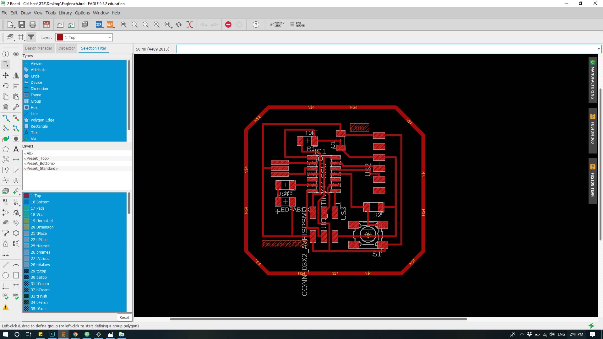
For the board design (echo hello-world board) i have used “Eagle fusion 360” software.
Files
Redrawing the Echo Hello-World board¶:
In order to redraw the board follow the steps below:
Step 1: download Eagle from the link above!
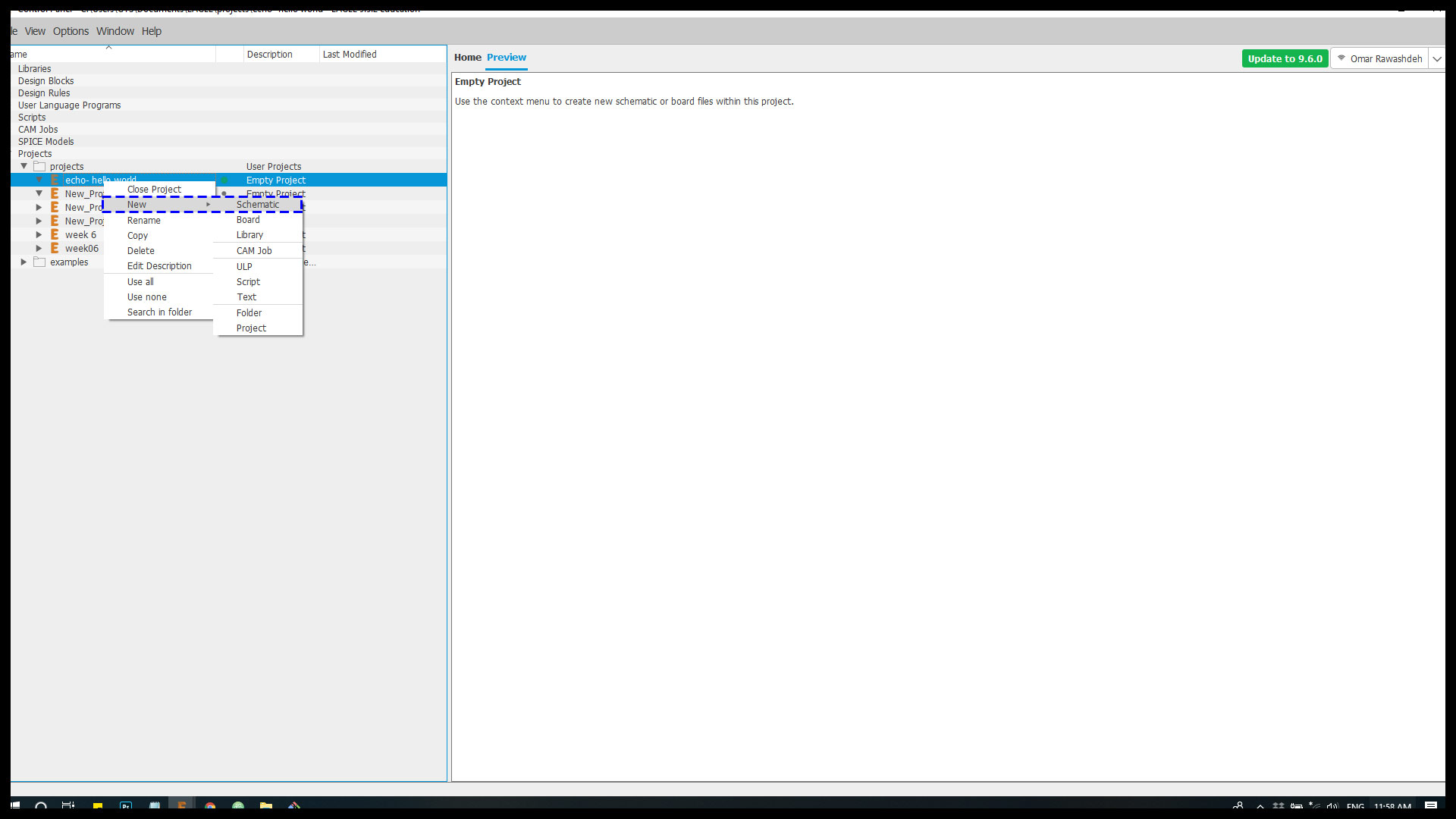
Step 2: then you gp to “file” from the tab panel and choose “New” after this click on project to start the process.

Step 3 : after thin right click on the project which is named “echo hello world” based on the assignment then choose schematic in order to get the components for the board.
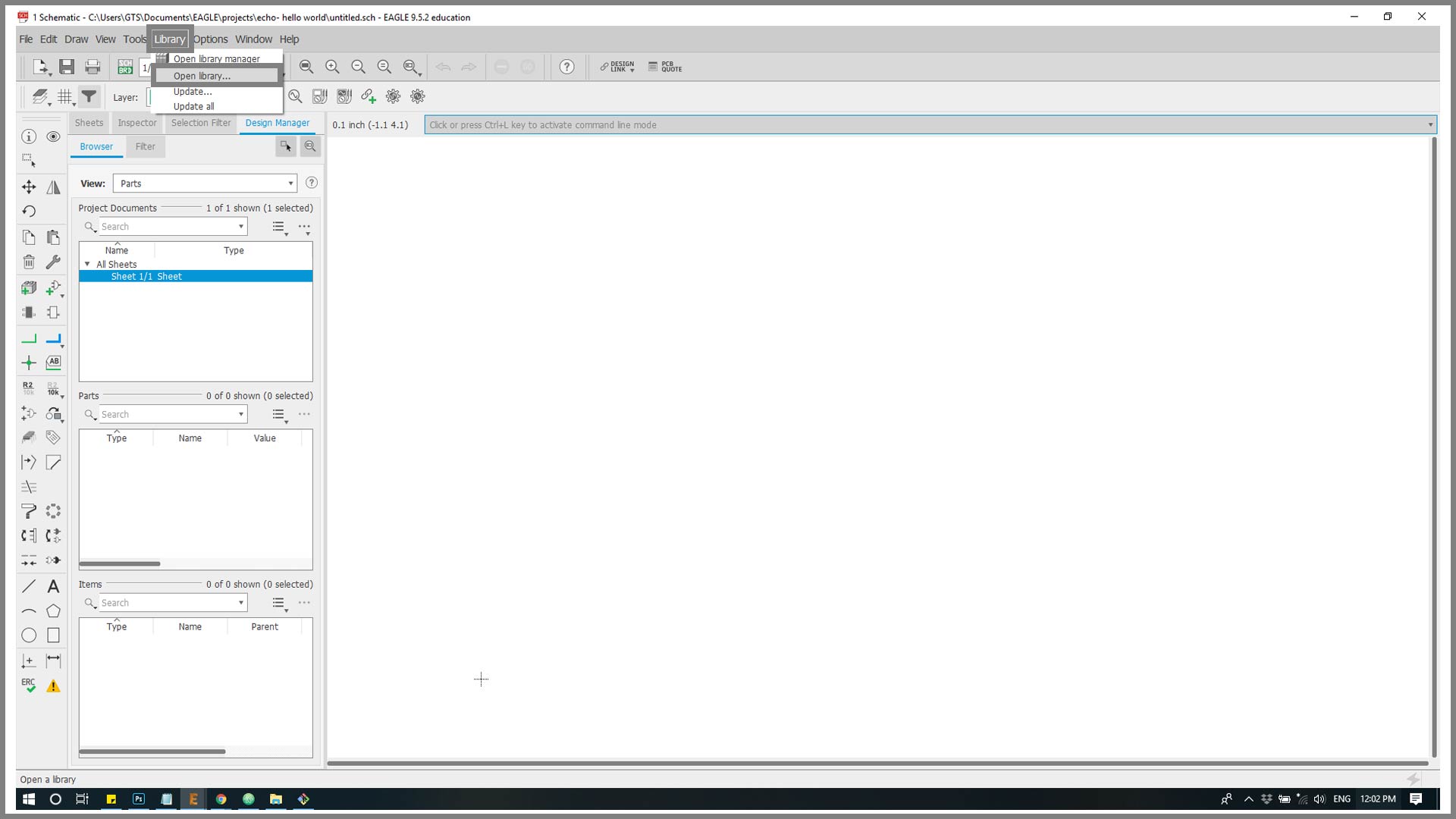
Step 4 :then from the upper panel choose “library” – ” open library ” too add the assignment components from “Eagle fab library”.
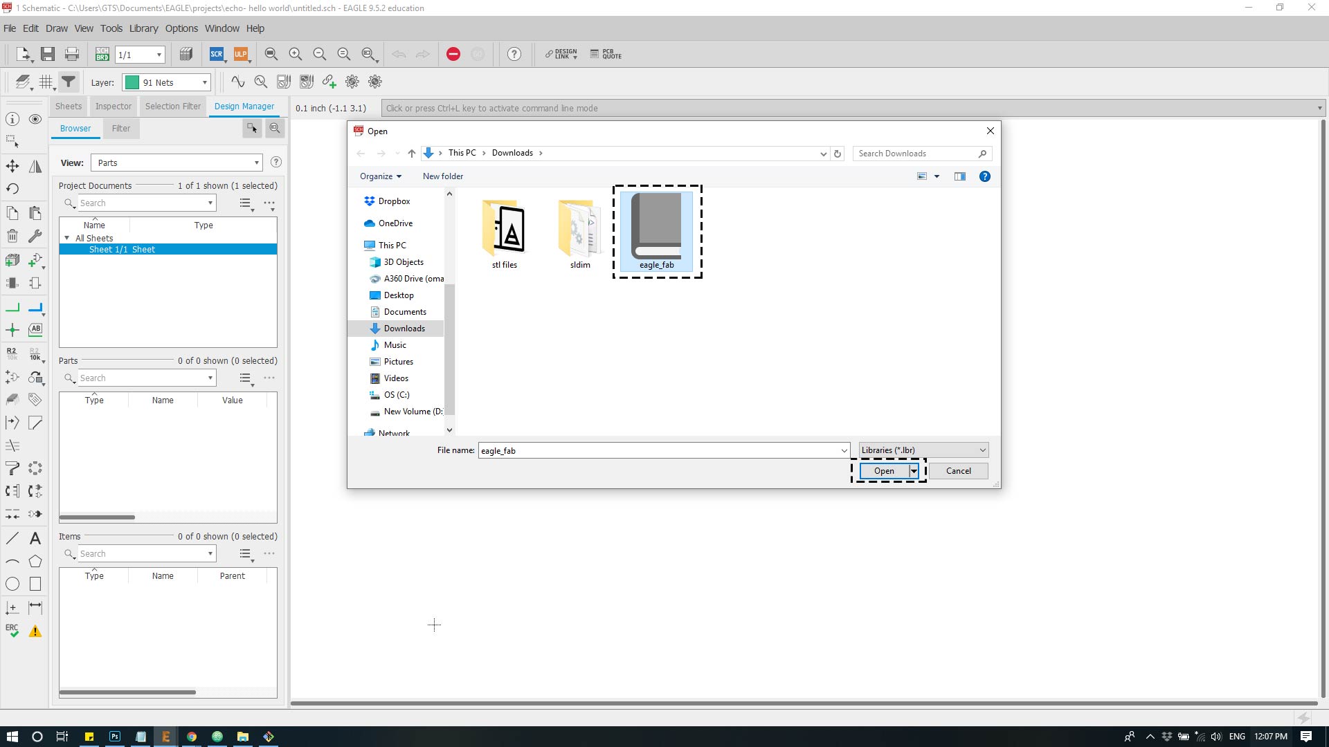
Step 4 : Add the library from the local pc the press open.
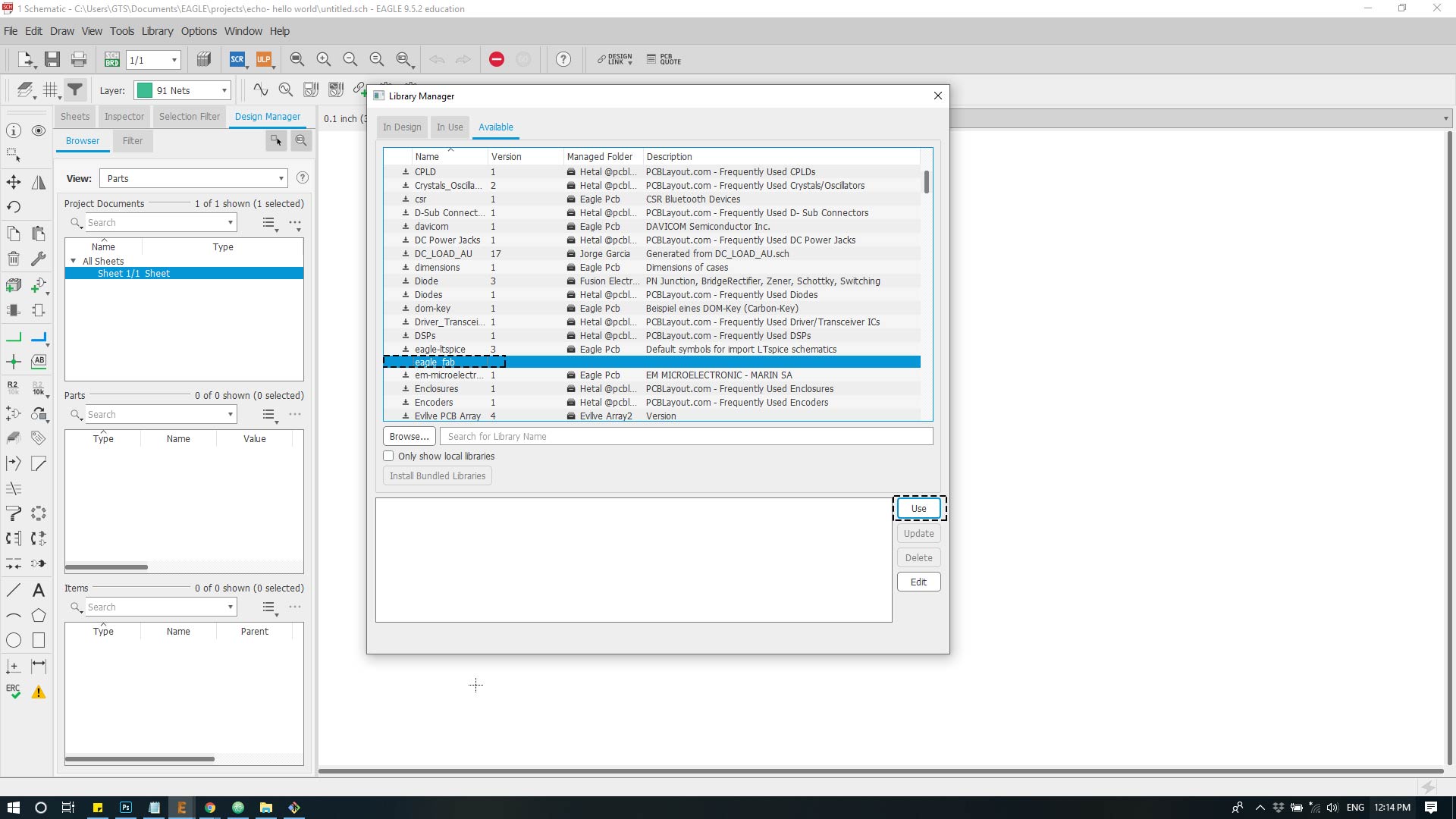
Step 4 : In this point the library has been added to the project, then choose the library from the upper panel then click on open library manger in order to activate the library’s components by scrolling the list down until reach the “eaglefab” then click use .
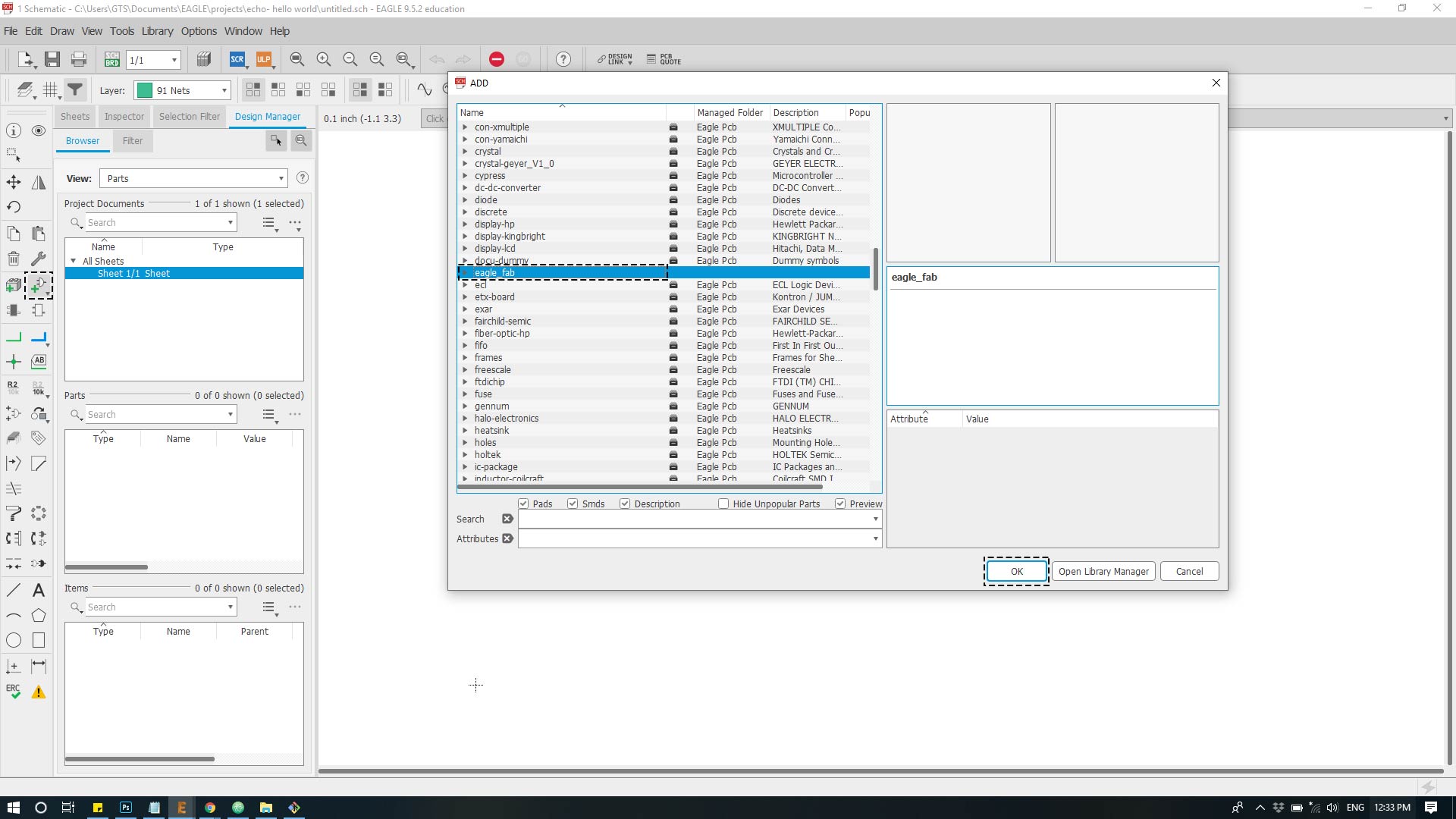
Step 4 : In this point the library is ready to be used in the schematic click from the side panel on “Add part” choose “Eaglefab” from the drop menu to get the components appered.
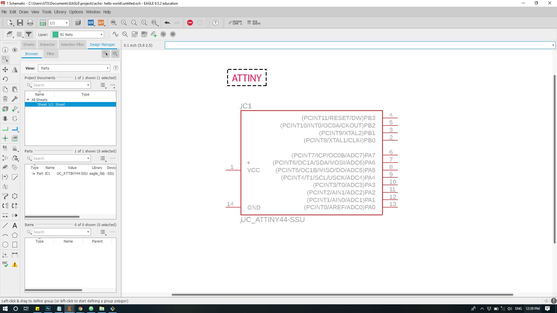
Step 5 : after this you choose the needed components for the board for example i picked “ATTINY 44”.
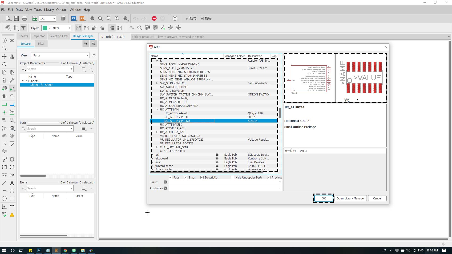
Step 6 : then the component will be added to the schematic plan in order to link it with the other components.
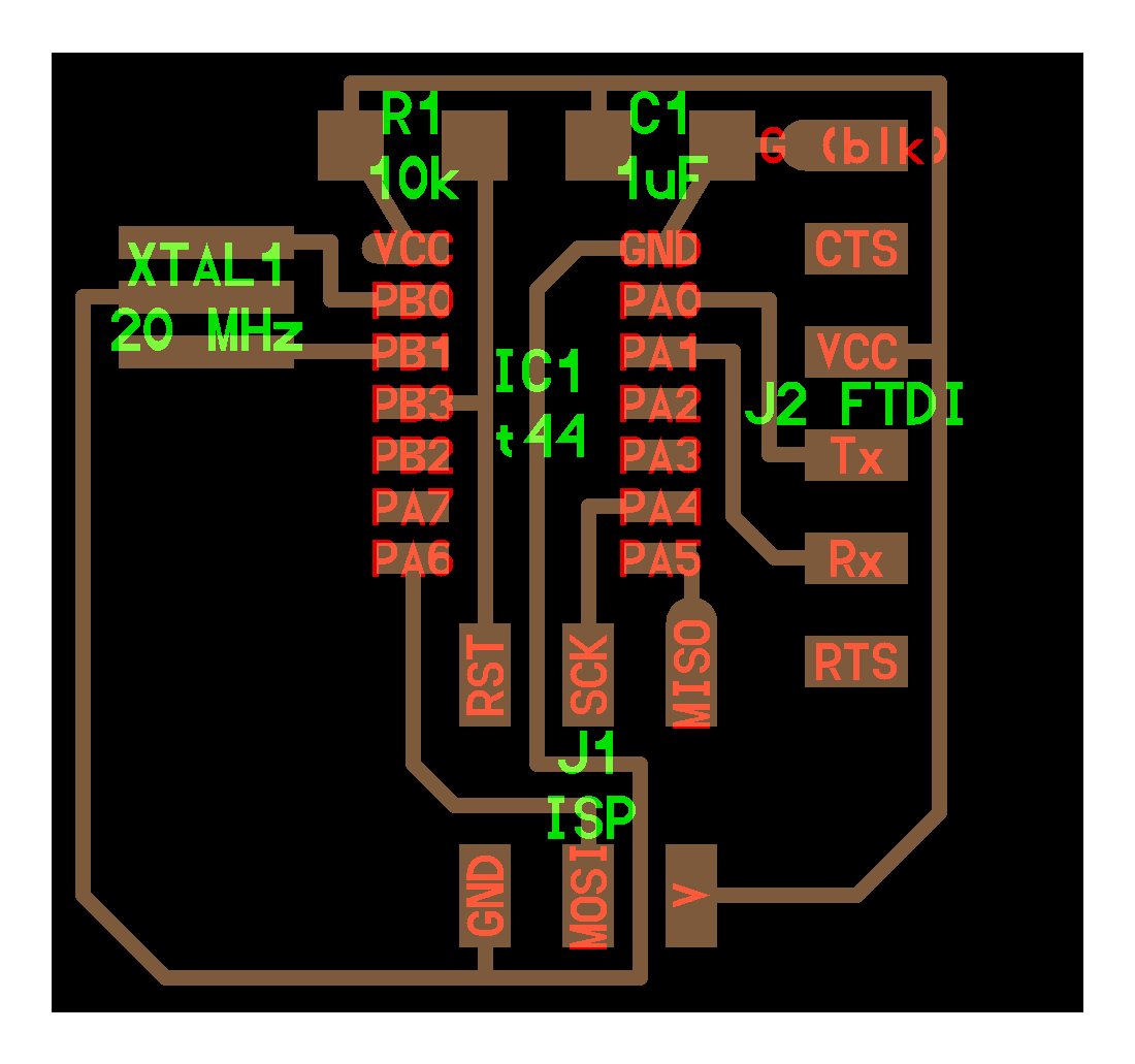
The default Components for hello World :
  Description                     Reference      Search       Lib Name                   Qty
  ATtiny44                      IC1             *tiny*         UC_ATTINY44-SSU              1

  Crystal20MHz                    XTAL1          *resonator*      XTAL_RESONATOR              1

  Header 3x2 ISP                   J1               *ISP*            CONN_03X2_AVRISPSMD            1

  Header 1x6 FTDI                   J2            *FTDI*           CONN_06_FTDI-SMD-HEADER      1

  Capacitor unpolarized 1uF     C1             *cap*            CAP_UNPOLARIZEDFAB           1

  Resistor 10kOhm                 R1               *resistor*       R1206FAB                      1
The added components:
  Resistor 10kOhm           R2            *resistor*            R1206FAB                          1
  Green LED              D1          *led*               LEDFAB1206                         1
  Push button              S1            *switch*             SW_SWITCH_TACTILE_6MM6MM_SWITCH   1
After adding the components the canvas and connected it to its pin.
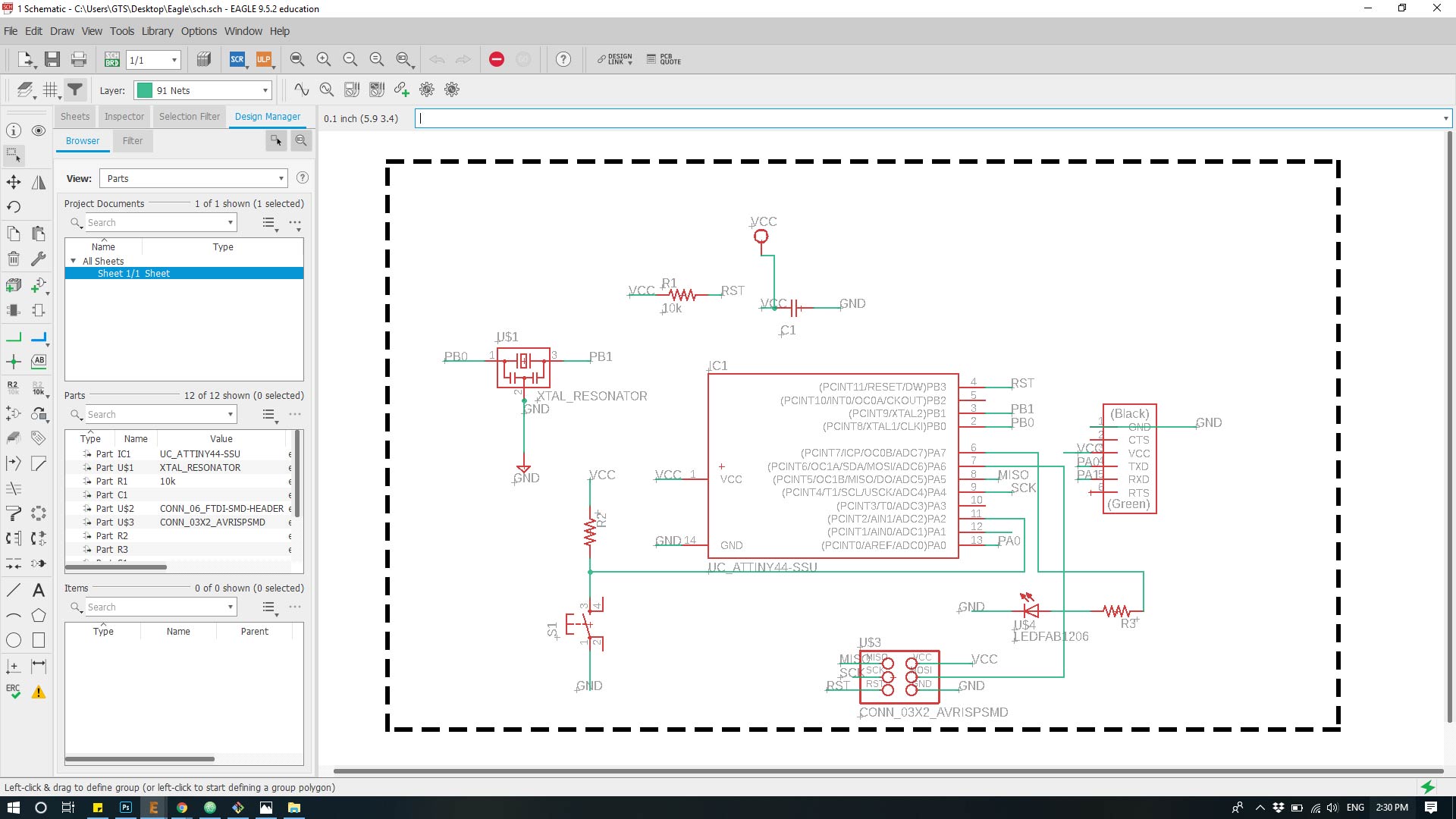
As per the original echo hello-world ATtiny44 board and using “Net” tool, add wiring to components. Make direct connections between components when possible. Using “Name” tool add names to open connections. Using names makes schematic less messy and works the same as direct connection between components. For example all open connections named “PB3” are connected together. Click “Yes” when asked to make connections.
Note :Click on Electrical Rule Check “ERC” to see if there are any errors or warnings in your schematic.
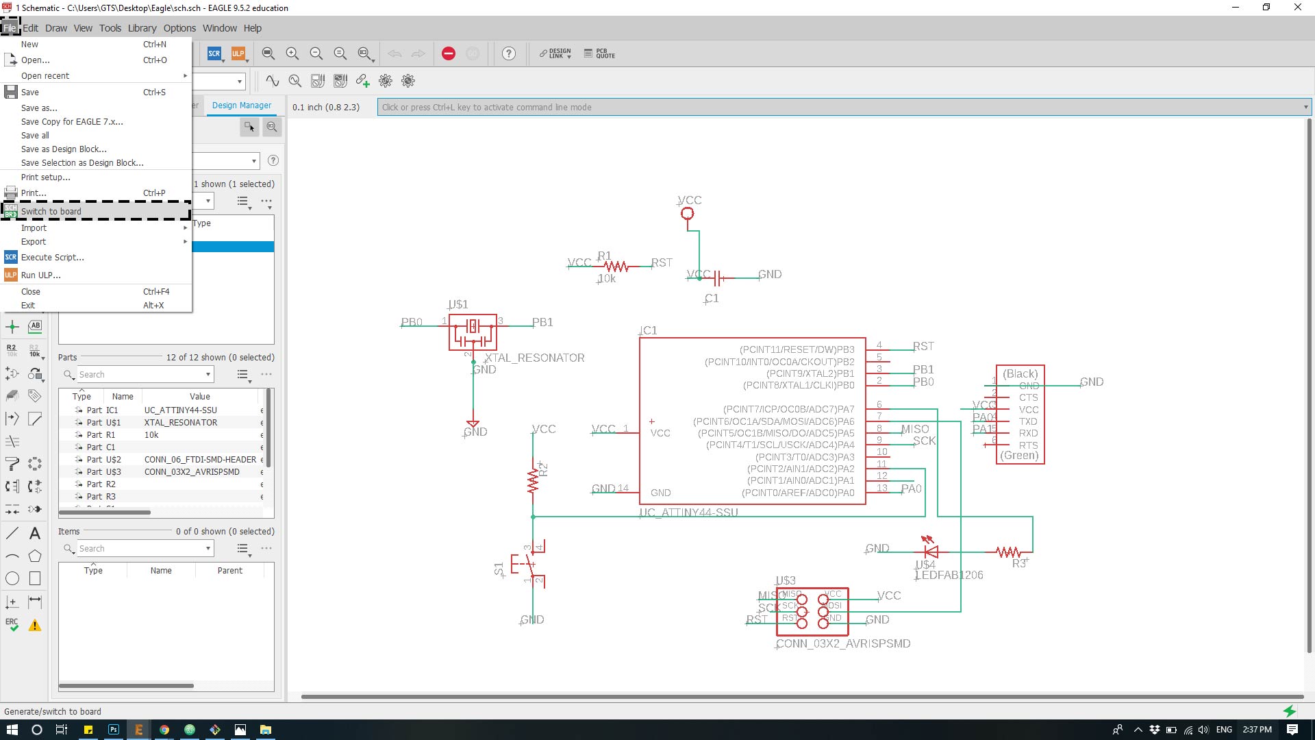
Step 7: After This export the schematic to the board design by Click on “file” then ” switch to board”.
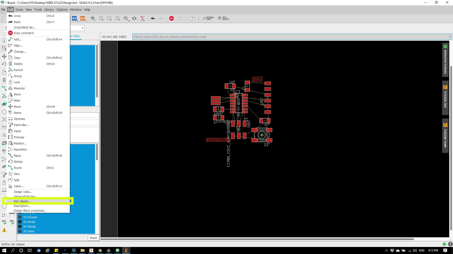
Step : Click on ‘Edit’ then choose ‘Net classes’
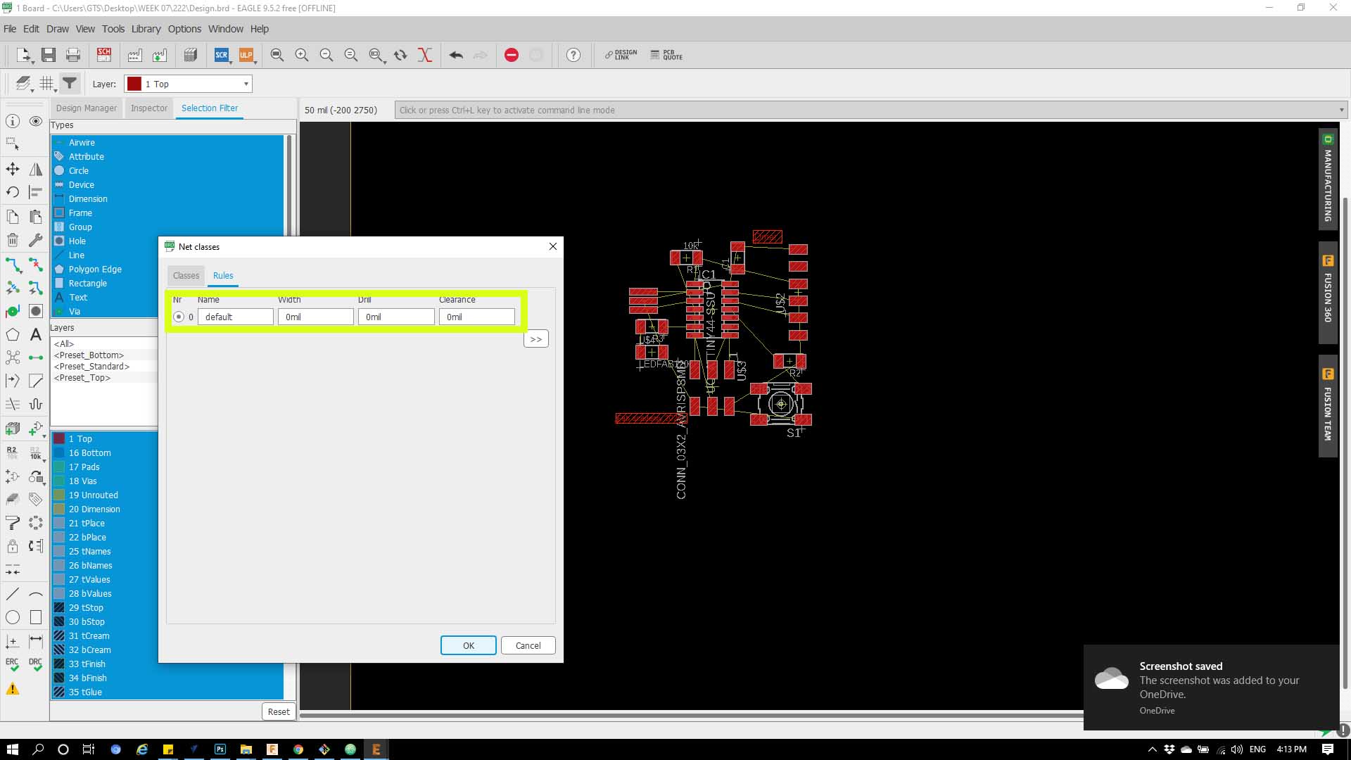
Step : from the dropped down menu choose ‘Rules’ Then on ‘Width’ put ‘16’ and mill ‘ put 1’ as shown below.
 s
s
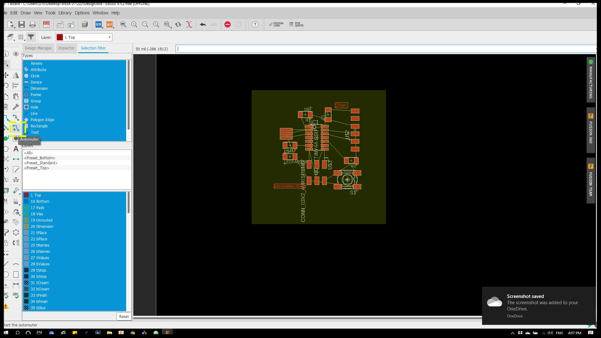
Step 8 : After i got the components in the board design i selected all the components then clicked on ‘AUTOROUTING’ command
Step 9 : Then you choose from the dropped down menu
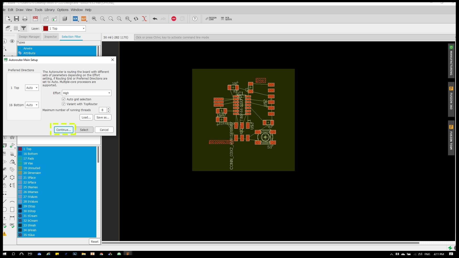
Step 10 : After exporting to design phase, link the yellow lines to each other to get the voltage in the circut.
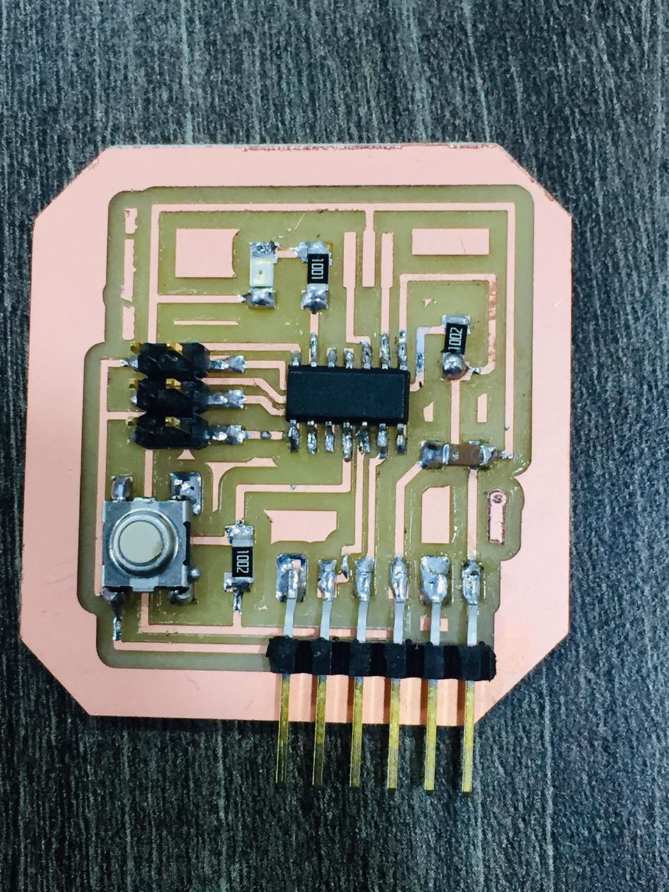
Hero shot
Programming