10. Input devices
Assignment Objectives
Individual assignment
Measure something: add a sensor to a microcontroller board that you have designed and read it.
Group assignment:(Will be done later) Probe an input device’s analog levels and digital signals.
Group assignment
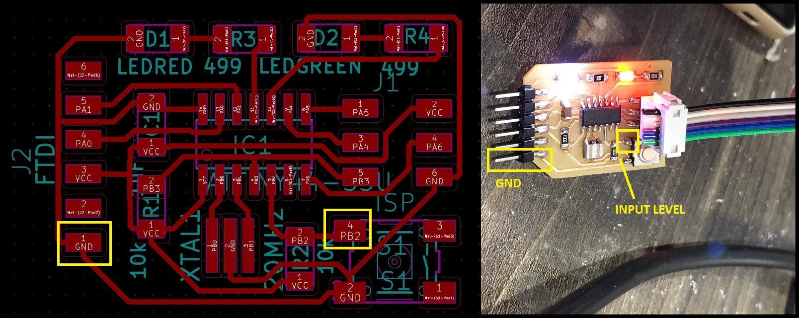
For the group assignment this week we have to probe an input device’s analog levels and digital signals and to do that we have measured the level of a push button that my colleague Aziz have done in its two states, normal and pressed.
-
The push button (normally open) is connected to Vcc through 10kOhm resistor, so in its normal state the level will be 5 V (digitally high). When pressed the level will be 0 V (digitally low).
-
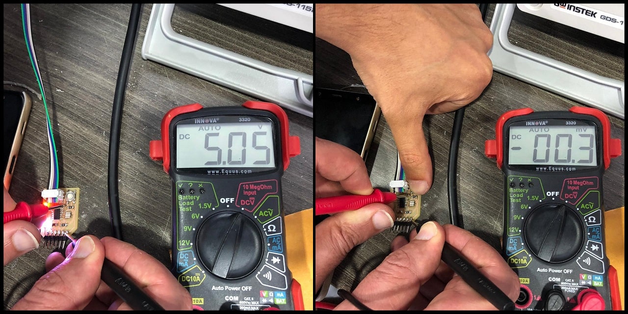
Using the digital multimeter, in the normal state the measured value is 5.05 V (digitally 1 or high), and when pressed, the measured value is -0.3 mV (digitally 0 or low).
-
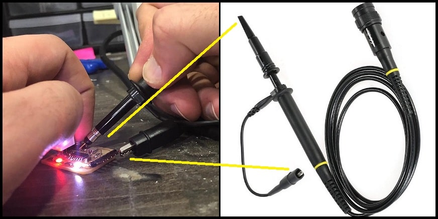
We used oscilloscope to measure the same input signal. To connect the oscilloscope probe, connect the spring loaded end (hock or clamp) to GND and the pin head to test point, which is the push button signal.
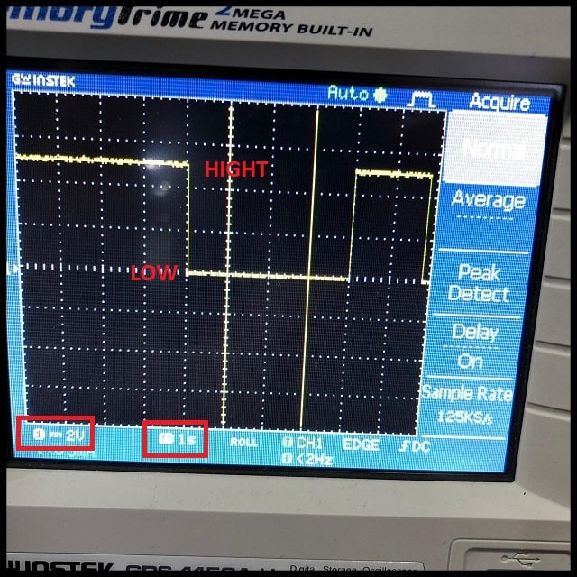
- Note that voltage scale is 2 V/division and time scale is 1 s/division. In the normal state, the signal height is 2.5 vertical divisions, which equals to 5V (2.5 divisions x 2 V/division). When the button is pressed, the level drop to fit over the zero line. The button had been pressed for 4 seconds (4 horizontal divisions x 1 s/division).
Individual assignment
Files :
For this week i want to work on the final board (Phototransistor + Servo):
Input
Phototransistor with Servo : The phototransistor works just like a normal transistor, where the base current is multiplied to give the collector current, except that in a phototransistor, the base current is controlled by the amount of visible or infrared light where the device only needs 2 pins.
microcontroller :
Atmega 328 :
Pinout :
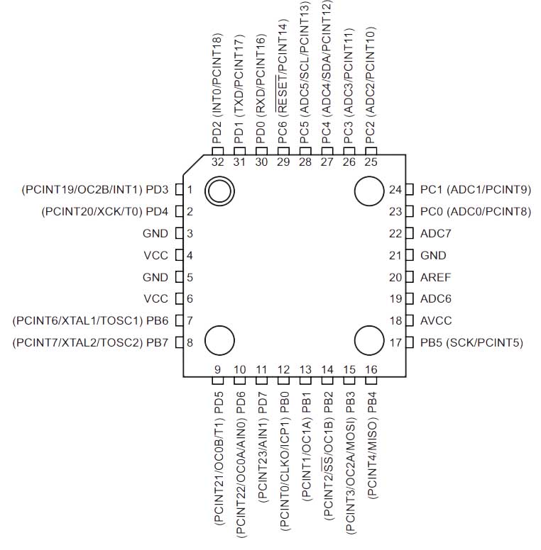
Pin Descriptions :
| VCC | Digital supply voltage. |
| GND | Ground |
| Port B (PB7:0) | Port B is an 8-bit bi-directional I/O port with internal pull-up resistors (selected for each bit). The Port B output buffers havesymmetrical drive characteristics with both high sink and source capability. As inputs, port B pins that are externally pulledlow will source current if the pull-up resi |
| Port C (PC5:0) | Port C is a 7-bit bi-directional I/O port with internal pull-up resistors (selected for each bit). The PC5..0 output buffers havesymmetrical drive characteristics with both high sink and source capability. As inputs, Port C pins that are externally pulledlow will source current if the pull-up resistors are activated. The port C pins are tri-stated when a reset condition becomes active, even if the clock is not running. |
Input sensor :
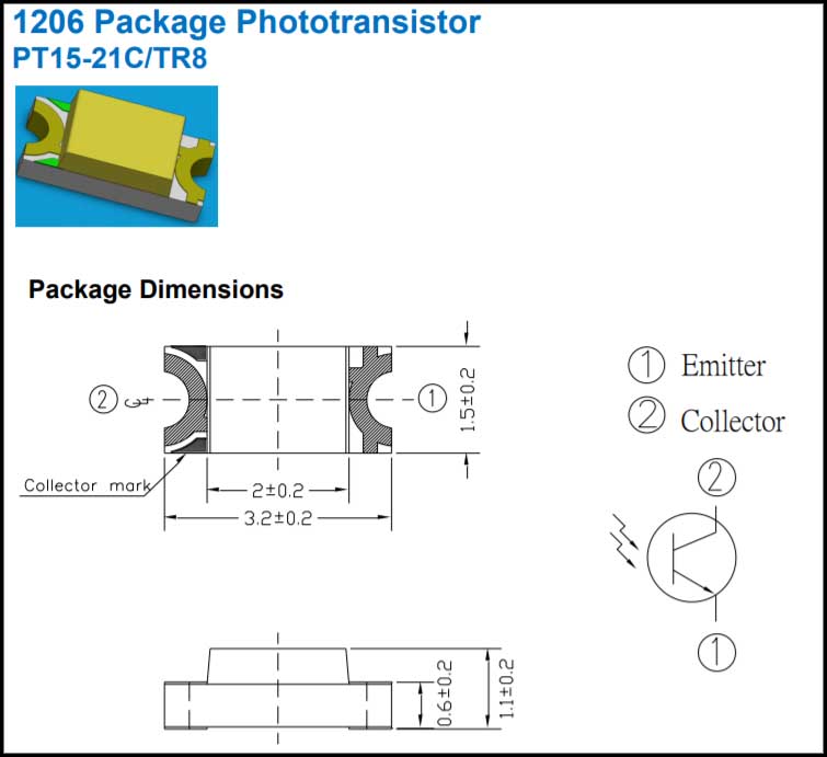
1206 Package Phototransistor:
It has to pin one is the Collector and the other is the Emitter
Working with Board Design :
As given in the Niel’s Board for the Input week as shown below im going to use same routing and add some components that fit my final project Board.
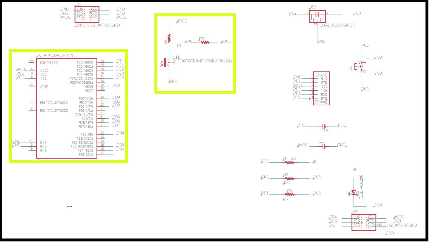
The Schematic
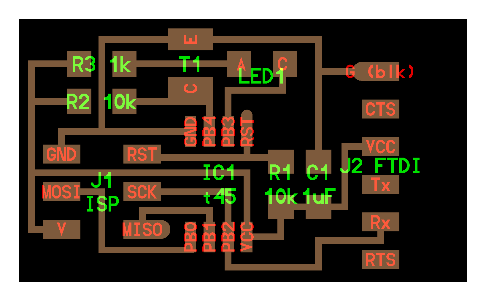
The Board Design
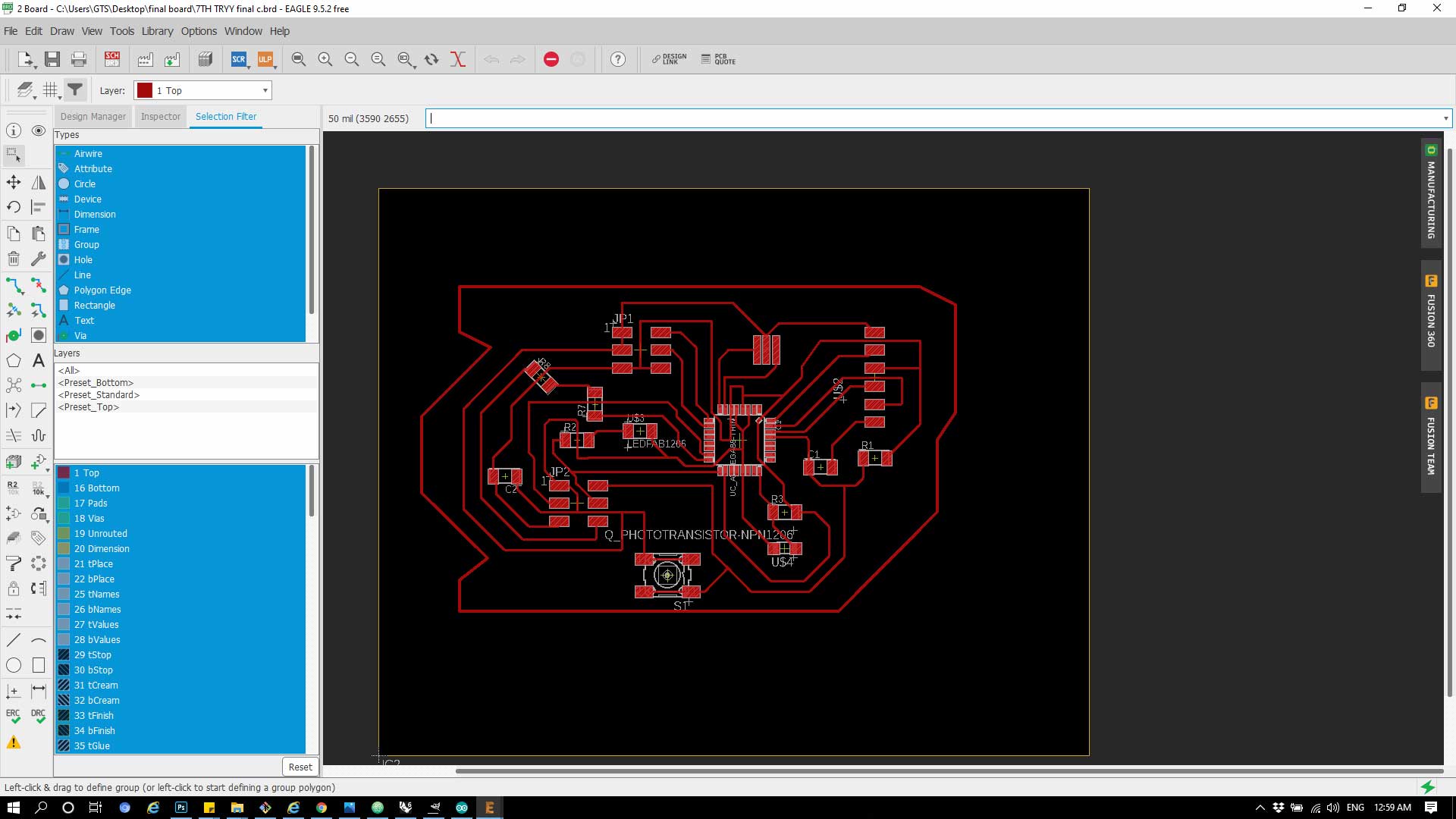
Check how export the schematic to design the board in Week7
| Component | Quantity | |
|---|---|---|
| 1 | ATmega328p | 1 |
| 2 | PIn header | 2 |
| 3 | XTAL | 1 |
| 4 | 10K resistor | 3 |
| 5 | 1K Resistor | 1 |
| 6 | LED | 1 |
| 7 | FTDI | 1 |
| 8 | 0.1 C | 1 |
| 1 C | 1 |
How to Export the Board to Image :
1- From File >> Export >> Image
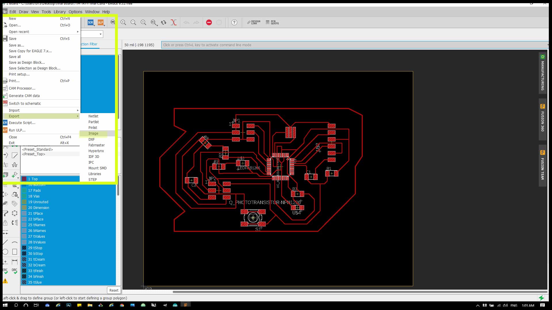
2- From the menu change the Monochrome and tick it and change the resolution to 1000 instead of 150.
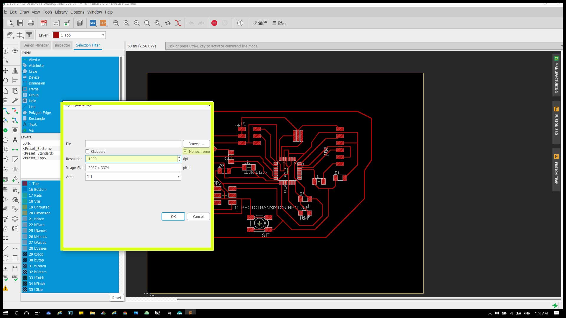
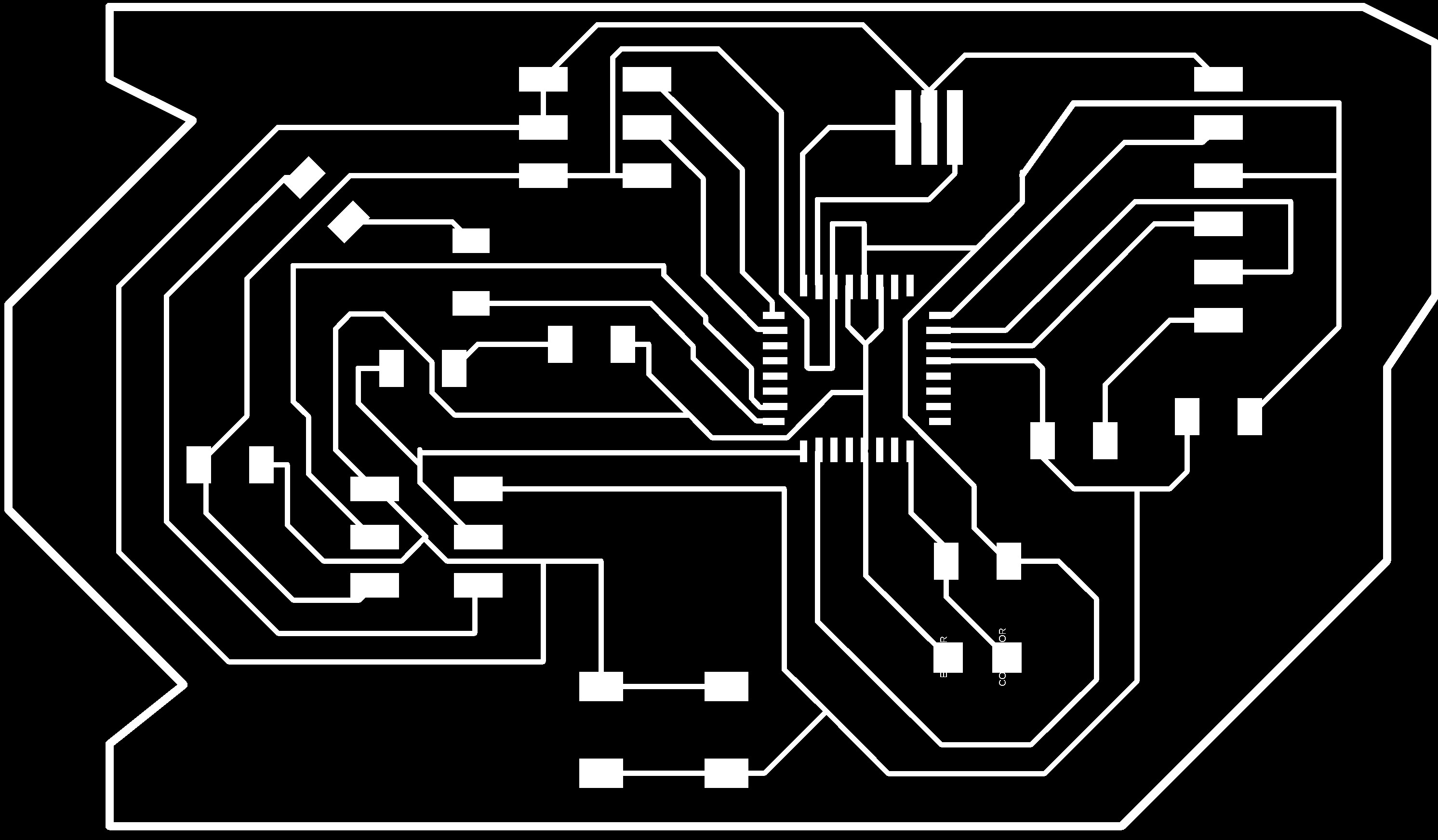
Final Png :
Check how to work with RML and mods in Week7
Code :
                #include <Servo.h>     // Library for Servo Motor

          int potpin=A0;// initialize analog pin 0, connected with photovaristor

          int ledpin=13;// initialize digital pin 13, output regulating the brightness of LED

          int val=0;// initialize variable val

          Servo myServo;   // define servo name


          /* The setup() function is called when a sketch starts. It is used to initialize variables, pin modes, start using libraries, etc. This function will only run once, after each power up or reset of the Arduino board. */


          void setup()

          {

          pinMode(ledpin,OUTPUT);// set digital pin 13 as “output”

          Serial.begin(9600);   // set baud rate at “9600”

          myServo.attach(5);   // servo pin

          myServo.write(0);     // servo start position

          }


          /* The loop() function executes the program repeatedly until Specified. */


          void loop()

          {

          val=analogRead(potpin);// read the analog value of the sensor and assign it to val

          Serial.println(val);// display the value of val

          analogWrite(ledpin,val);// turn on the LED and set up brightness(maximum output value 255)

          delay(10);// wait for 0.01

          if(val>250)

          {

          myServo.write(90);

          }

          else

          {

          myServo.write(0);

          }

          }
The code controls the light intensity from 0 - 1023 and rotate the Servo from 0 - 180 degree.