8. Computer controlled machining
Assignment for this week: Group assignment test runout, alignment, speeds, feeds, and toolpaths for your machine
Individual assignment
Files :
make (design+mill+assemble) something big
Group assignment
Machine
Features
      XY Move Speed :(with full cutting force)  Variable, max. 600”/min.


      Z Move Speed
      (with full cutting force) Variable, max. 360”/min.


      XY Positioning Speed  Variable, max. 1800”/min.


      Z Positioning Speed   Variable, max. 900”/min.


      Step Resolution   0.0005”
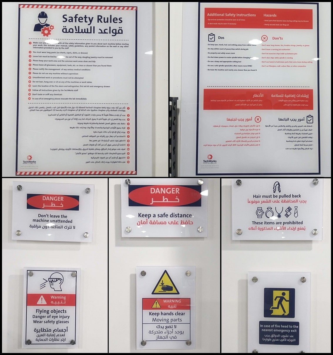
Safety: Follow the safety sign’s rules before using the Machine plus know how to stop the machine before to know to start it!

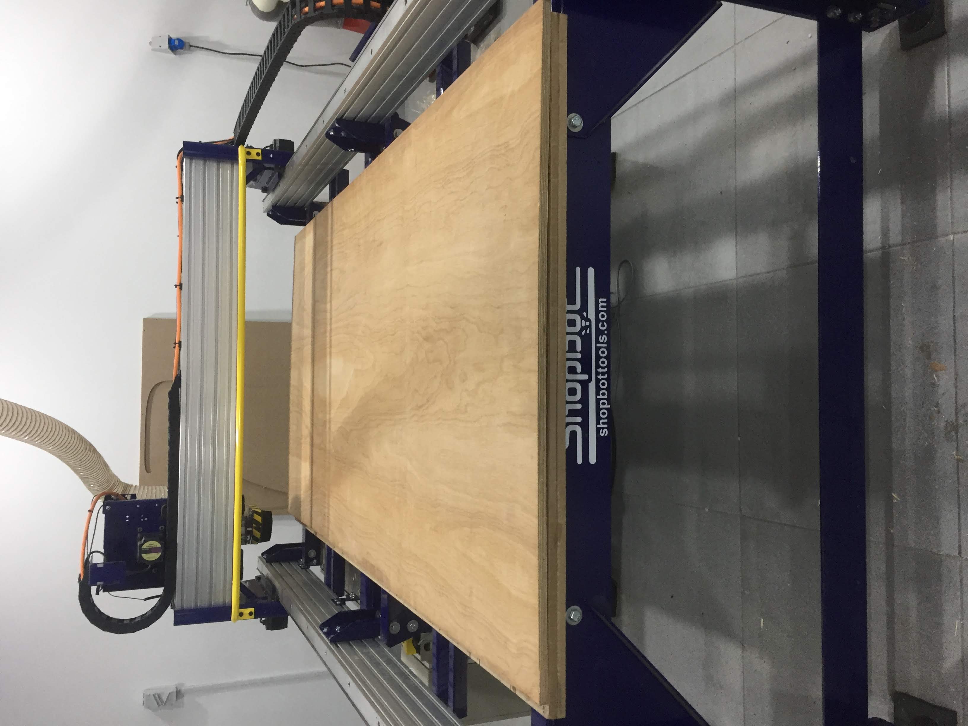
Machine Overview
The ShopBot PRSalpha ATC 96-60-8 is an affordable full-sized gantry tool for CNC cutting, drilling, carving and machining of wood, plastic, aluminum and other materials.
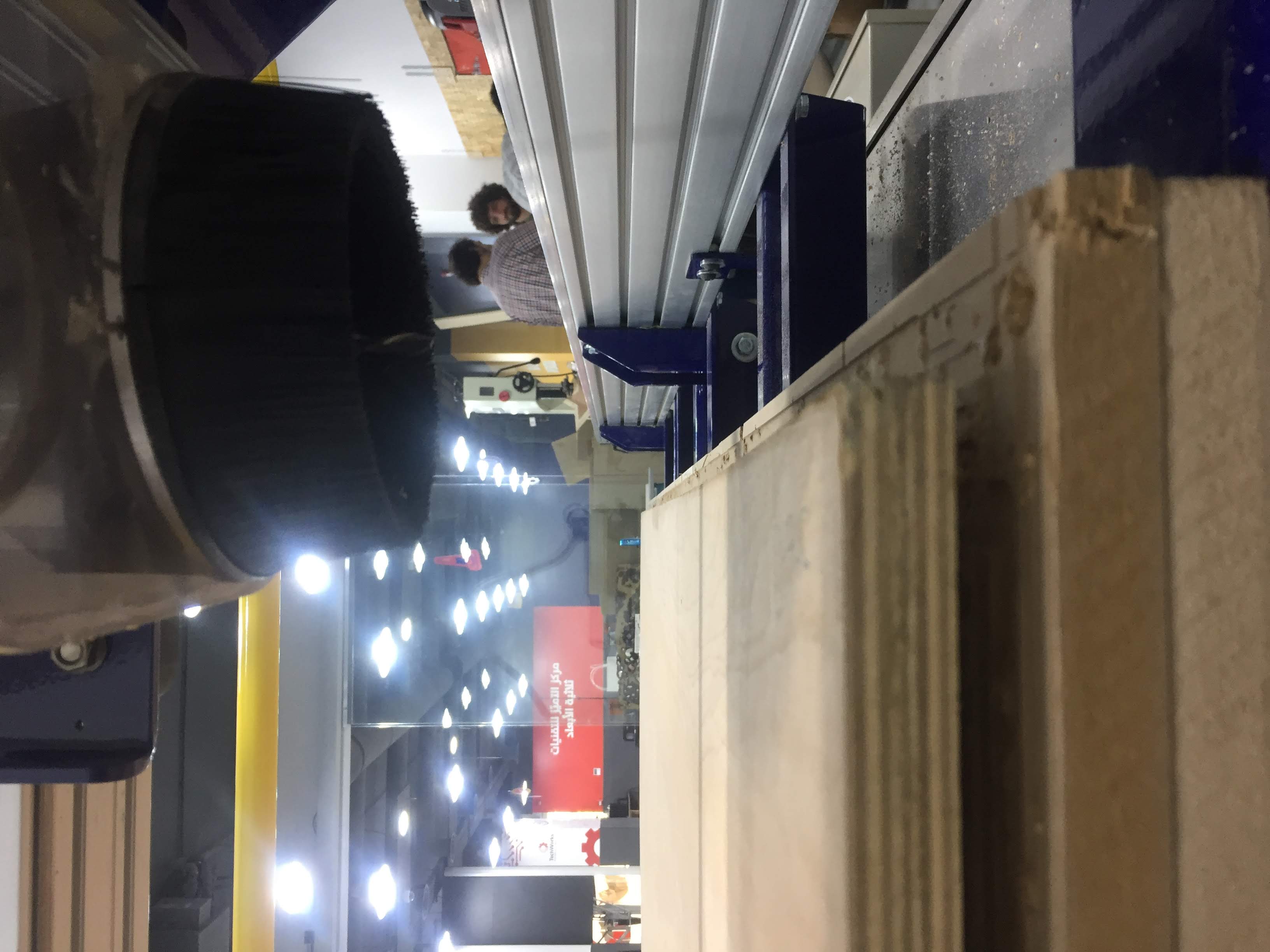
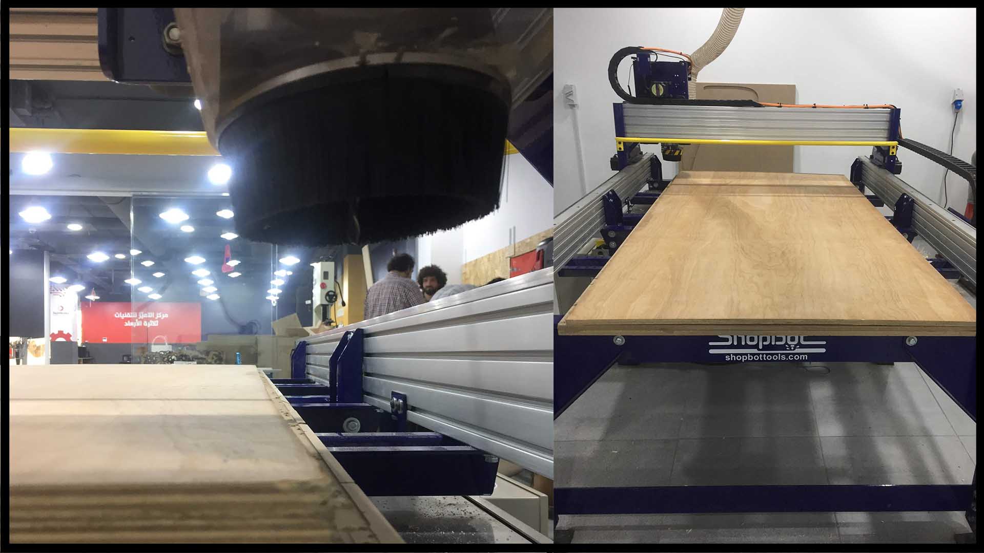
Vacuum :
It is connected direct the machine bit to clean the left over chips.
Tooling :
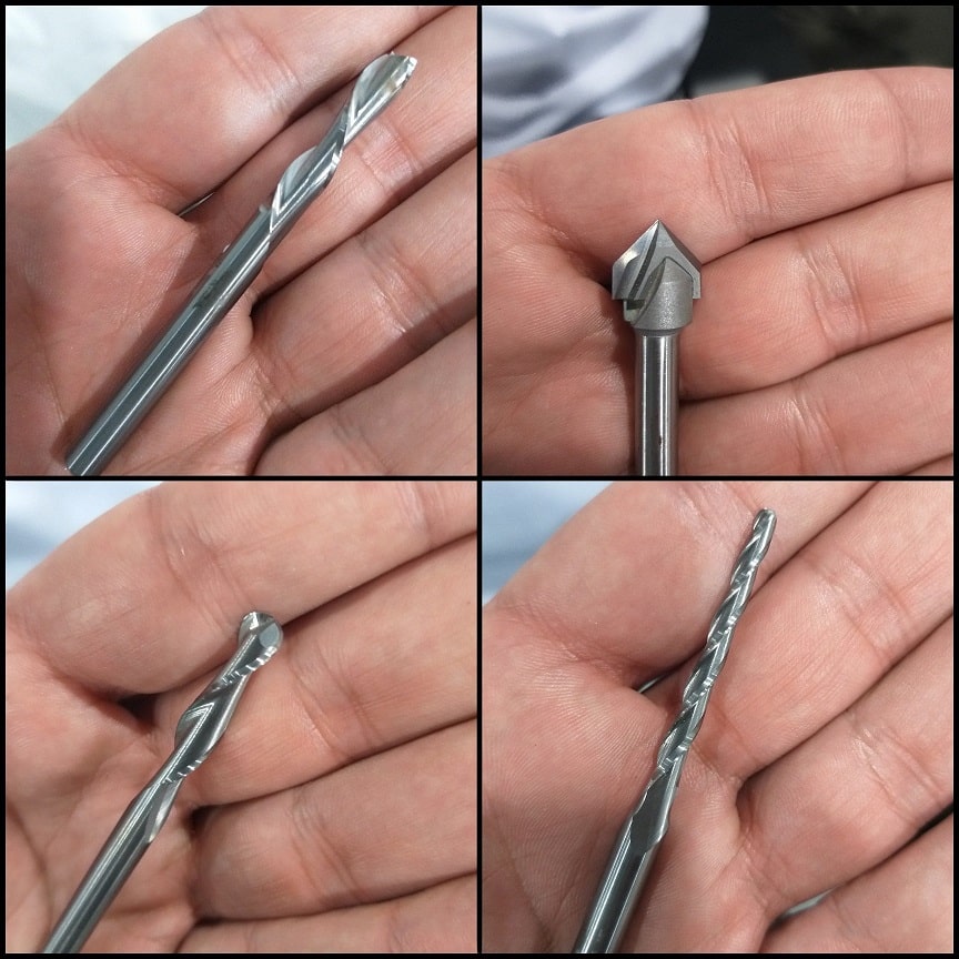
We visually inspected different types of endmills and used two of them to complete our tests. We inspected the spiral, v-carve, ball nose and tapered ball nose endmills. Each has designed for a specific purpose and all can be used in a CNC router.
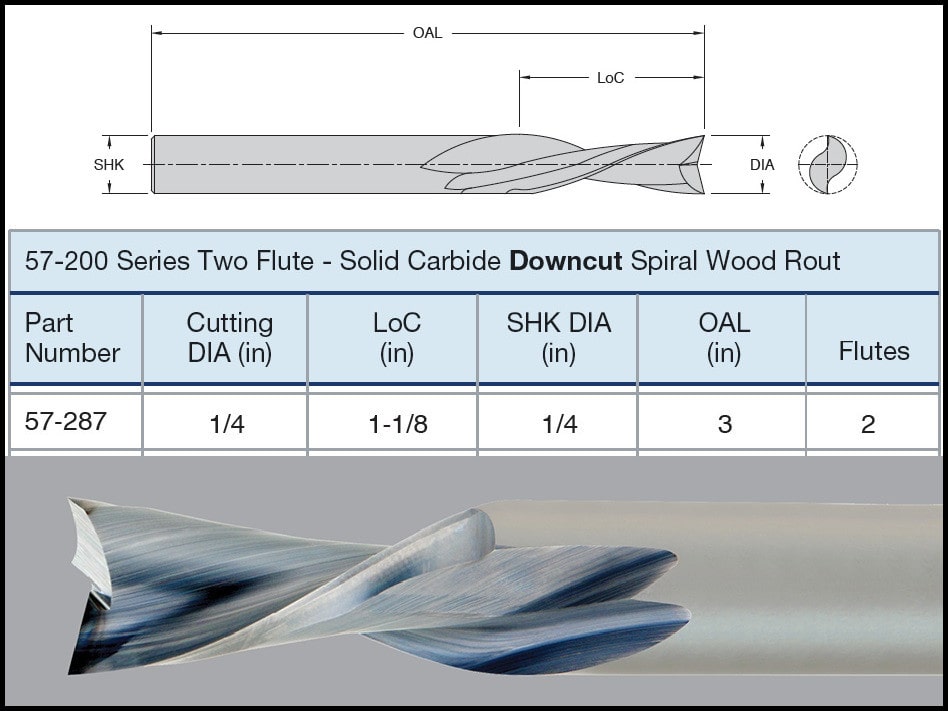
For the tests we used LMT.ONSRUD 57-287, a downcut spiral bit. It has two flutes and a center-cutting tip. Then we repeated the same test using LMT.ONSRUD 52-287 a similar upcut endmill. These endmills are designed for soft Wood, hard Wood, wood composite.
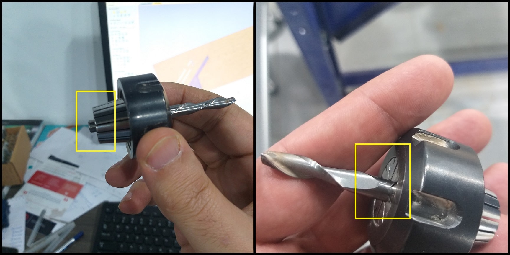
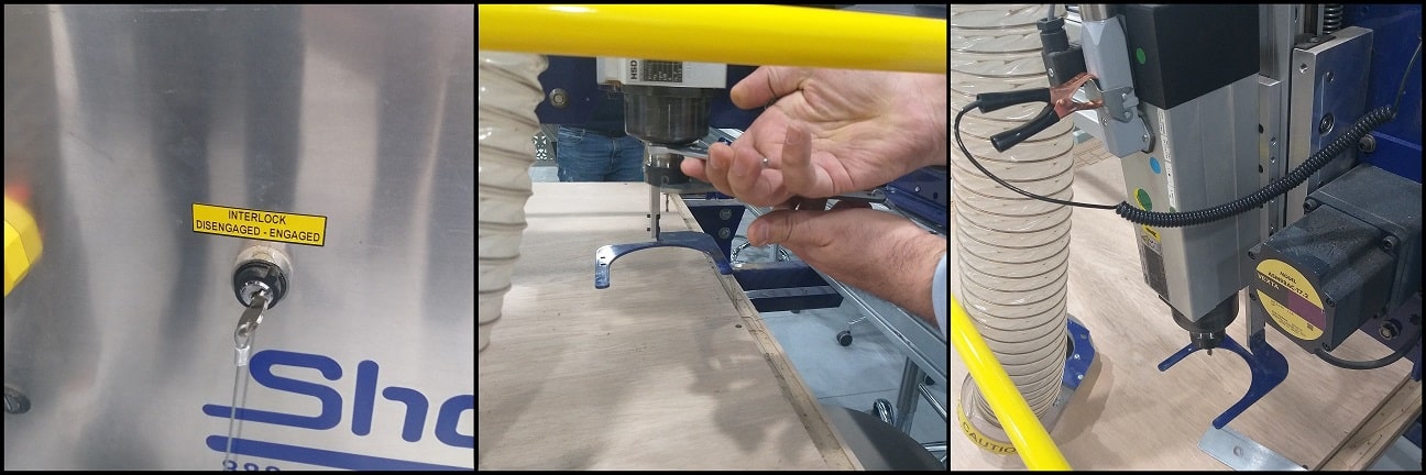
To minimize or eliminate runout (“Runout is the tendency to spin the tool around a centerpoint that is not the tool’s center. It makes the tool wobble instead of spinning cleanly and increases chip loads”), maximum part of endmill shank should be inserted to the collet. The end tip of endmill shank might flush with the collet and if possible it might go beyond the collet end. All ways, a clearance distance between the cutting edges and collet face should be maintained.
To tie the collet and endmill to the spindle, we used to supplied wrenches. A simple safety feature is provided in the machine that one of the wrenches is attached through a string to the “INTERLOCK DISENGAGED - ENGAGED” key. So whenever you need to use the wrench you have to remove the key and spindle cannot be started. Note that to fix the collet to the spindle the dust extractor should be removed first.
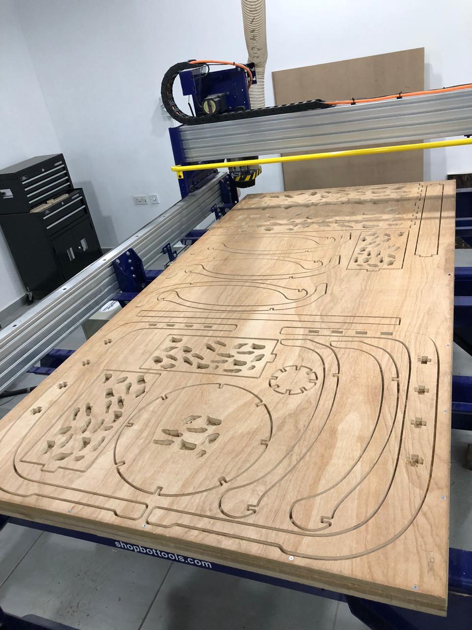
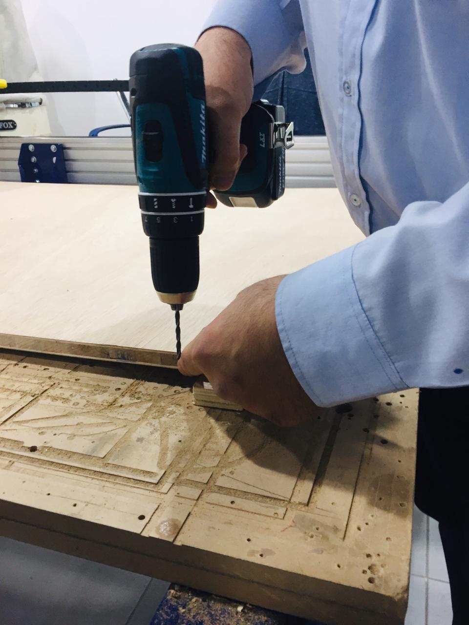
Fixing The Work Piece The machine has MDF sacrifice board fixed on bed. If the endmill penetrates the work piece the extra cut would happen on the sacrifice sheet. This way we make sure machine body and tool won’t be destroyed. Holes were drilled to work piece and wood screws used to fix it to sacrifice board. Note that when we work on software, we define “Boarder Gap” to be 30mm. Cutting will not be happening on this area, so we can use it to put the screws. On the other hand, if the work piece is misaligned to the machine axes, the boarder gap will compensate misalignment and cuts will be inside work piece.
Working on VCarve Pro
We used 17.0 mm latte sandwich uncovered wood to make the tests. Stock was measure using a caliper and the actual size was 17.2 mm. The actual size should be used in machine software. Step-by-step guide for working on VCarve Pro is provided in week assignment section.
Hero Shoot!
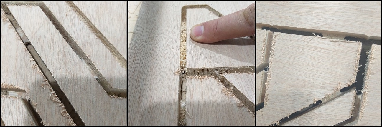
The first image compares the quality of cut on surface using downcut and upcut bits. Note that the chips appears attached to the surface (left) when using an upcut bit, while surface cuts appears better when using downcut bit (right). In the second image chips are much remained between cuts when using a downcut bit. Also, a downcut bit generates more noise compared to an upcut bit.
The third image shows tabs (joints) between target cut and work piece. This will keep stock in place while performing the cuts.
Individual assignment
Make (design+mill+assemble) something big.
File download
- Designing nature back into Furniture
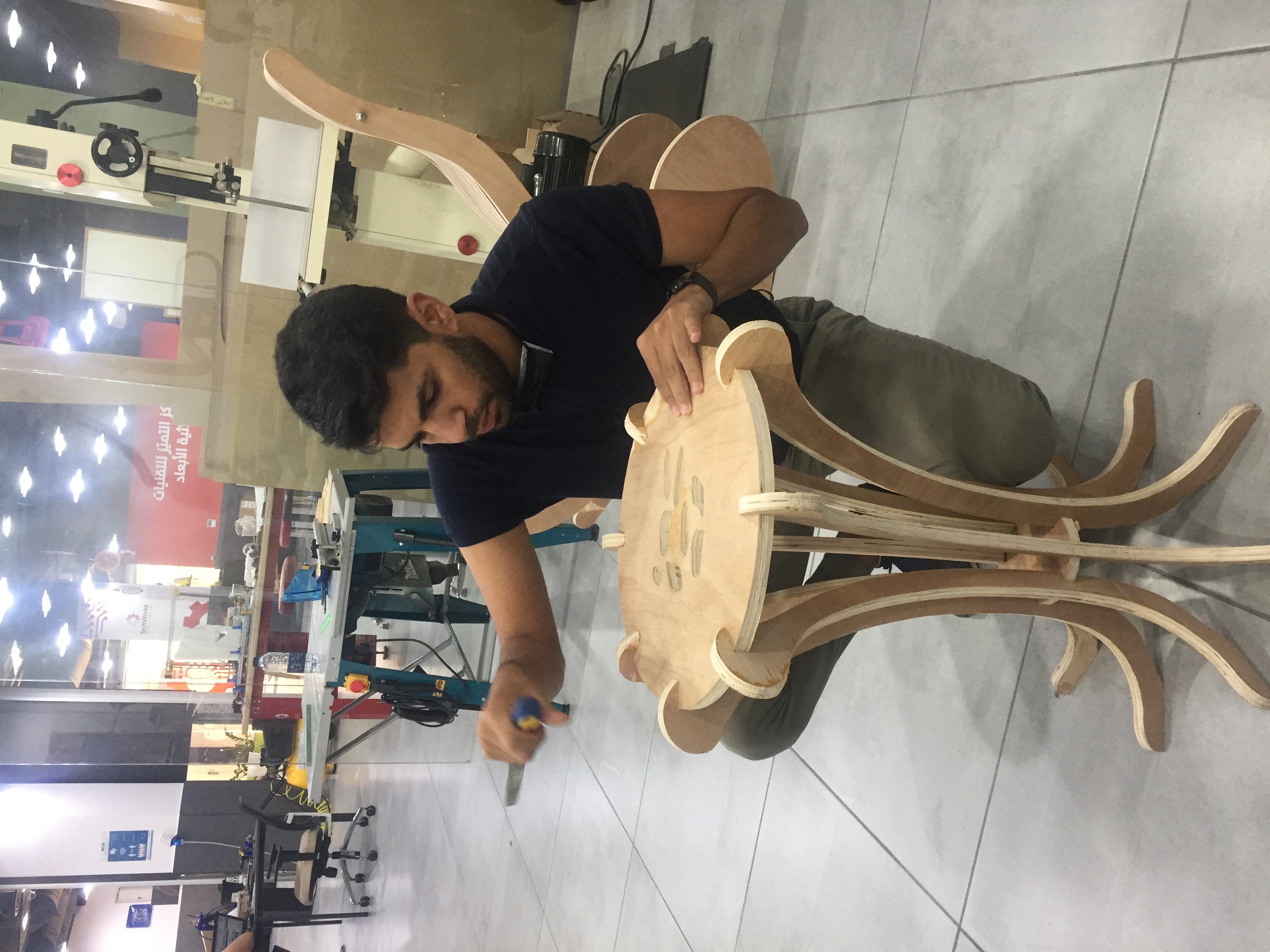
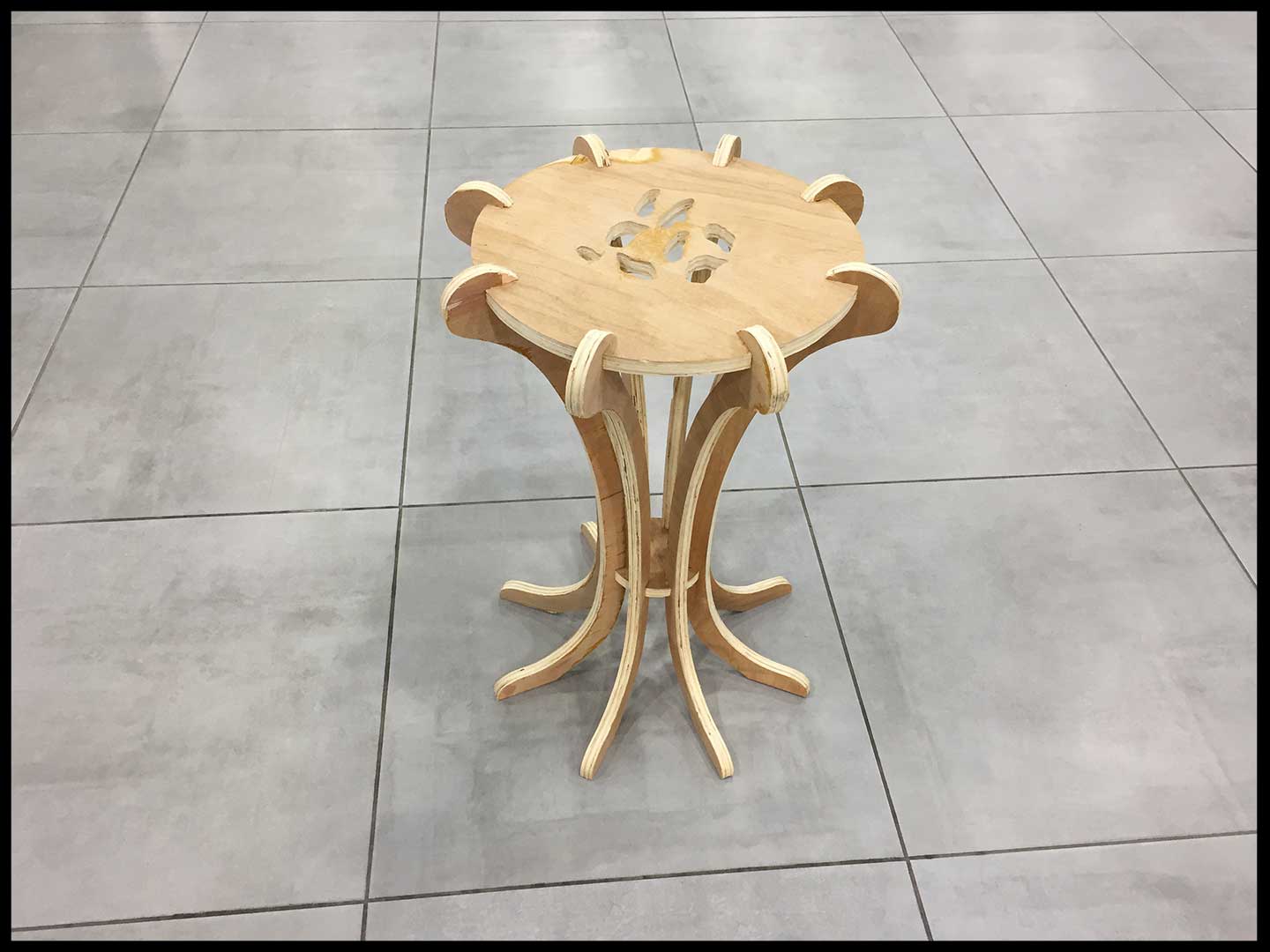
Mushroom Furniture
For this week assignments the inspiration was from the mushroom,

Step 1: I Have used Autocad for 2D design the tables.
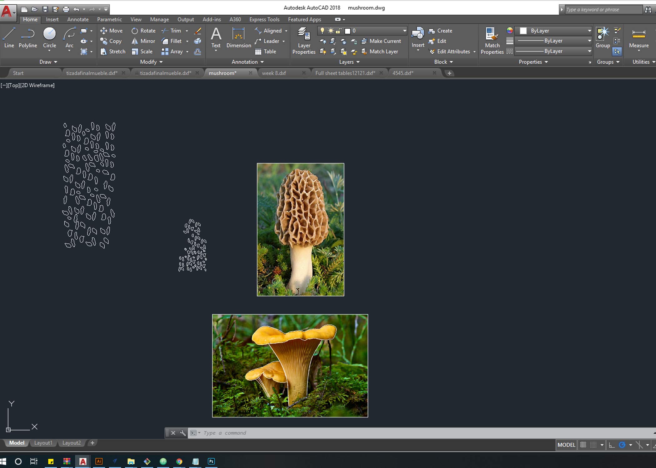
Step 2: after taking the line from the attached pics i got the main geometry for the design using SPLINE command thats helps get organic waves .
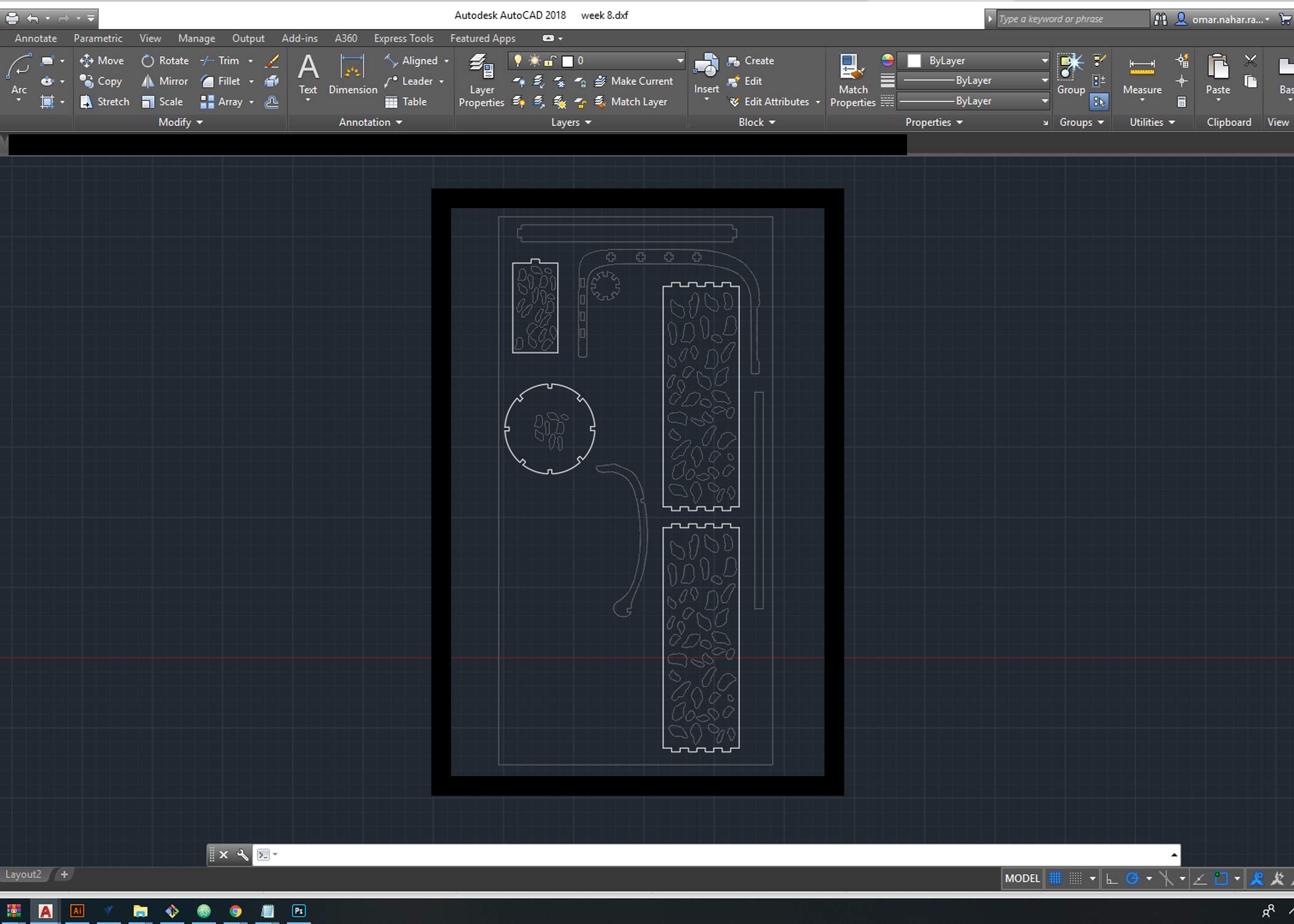
Step 3 : in the design i made the press-fit joints in each part to fit the parts together with gap (1.3 cm)
Step 4 : exported the file to DXF in order to import it to V-CARVE.
Working on VCarve Pro
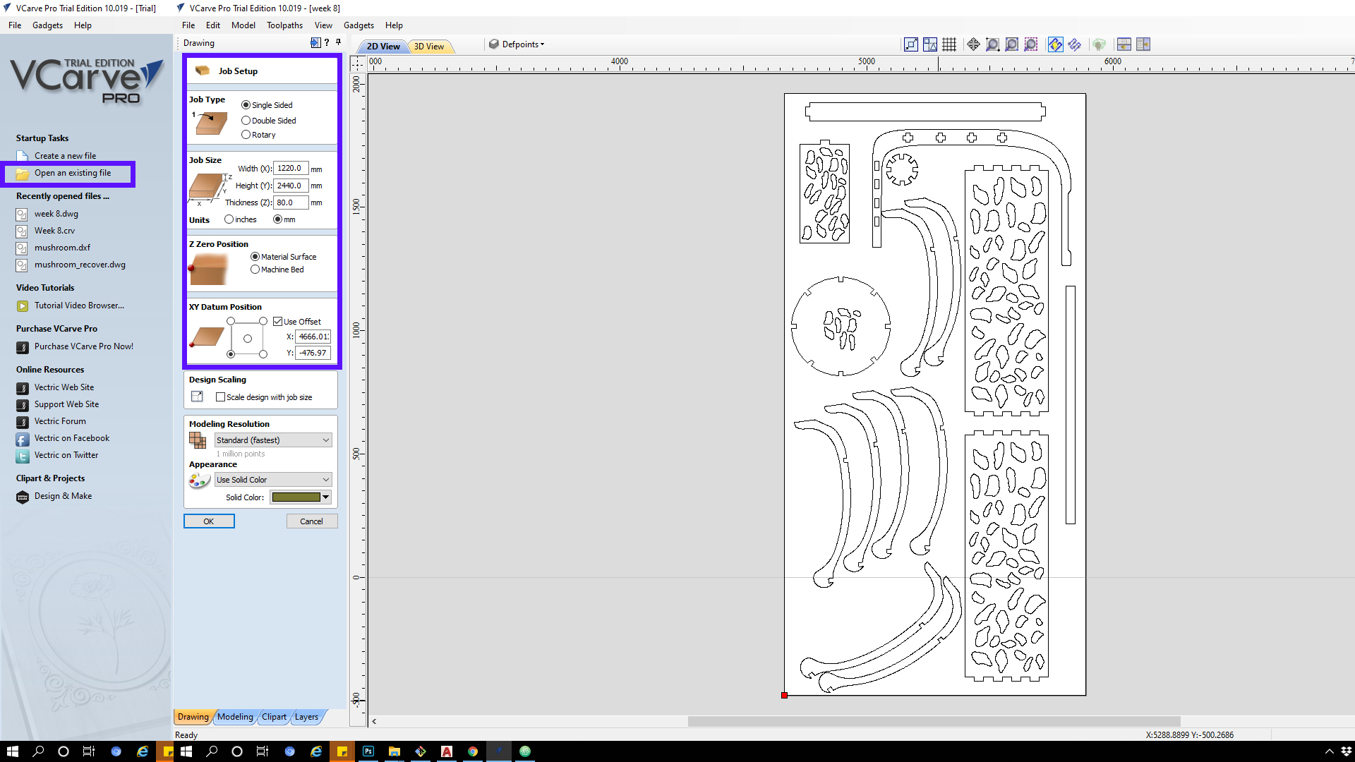
Step 1:
Open VCarvePro and click on “Open an existing file”. choose ‘Table.dxf’ file and open it. then a drop menu will apper to Insert job settings then click “Ok”. The board I used is 2440mm x 1220mm and measured thickness is 17.00mm - 16.90mm so i inserted 17.00mm
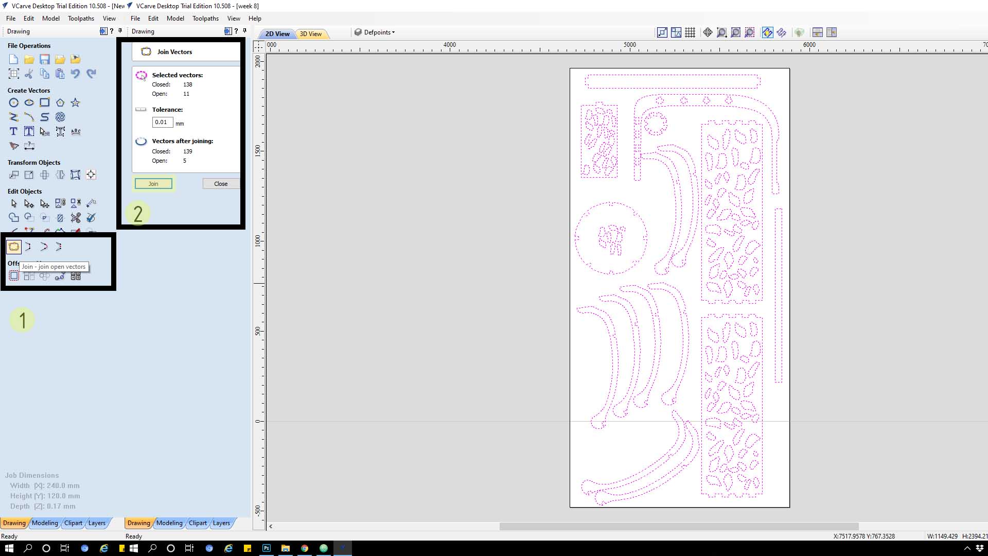
Step 2 : select all the parts on the canvas then click on “Join - join open vectors”, This will join lines and curves in each part so it will be treated as a single toolpath.
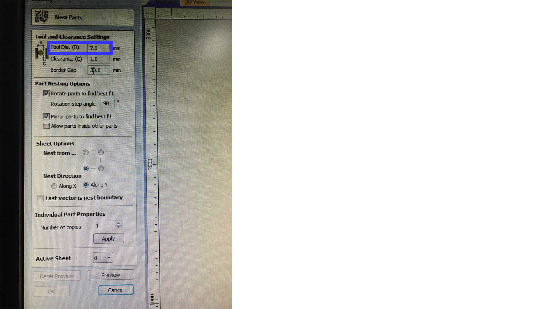
Step 3 : Nesting, ‘The tool Dia.’ value is the gap around each object (7.0) and the Clearance is the gap between each object and it is ‘Tool Dia.’ so the total of the gap between each object is 7.0+1.0 = 8.0 * 2 = 16.0 mm
Work with toolpaths
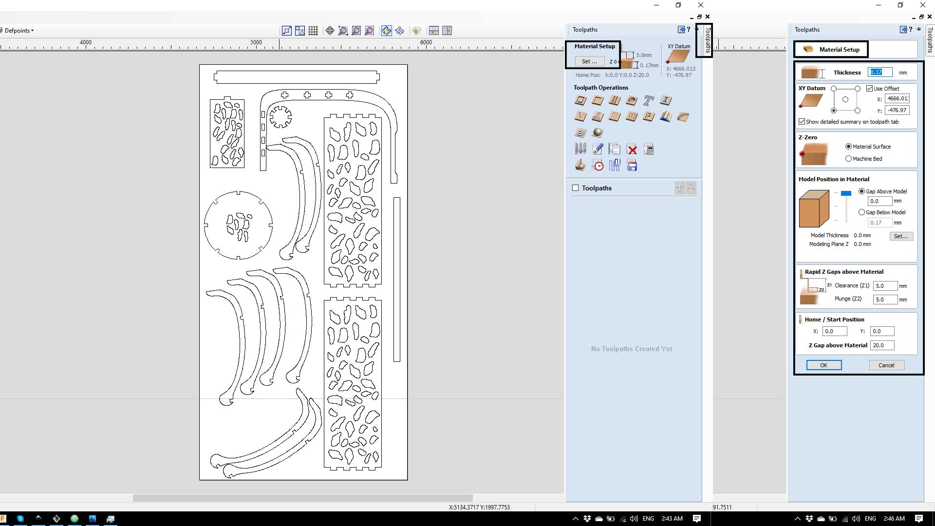
Step 1 : Click on the right top corner ‘toolpaths’ then click on ‘Material setup’ then click on that you can choose the settings, then click ok the apply the settings.
Step 2 : Now we generate the toolpaths and i have used the “Pocket toolpath” for the joints and the “profile toolpath” for the pieces :
2d and Pocket ‘toolpath’ :
click on ‘pocket toolpath’, from the menu click on the second bar and click edit then choose the settings that have been provided in the group assignment.
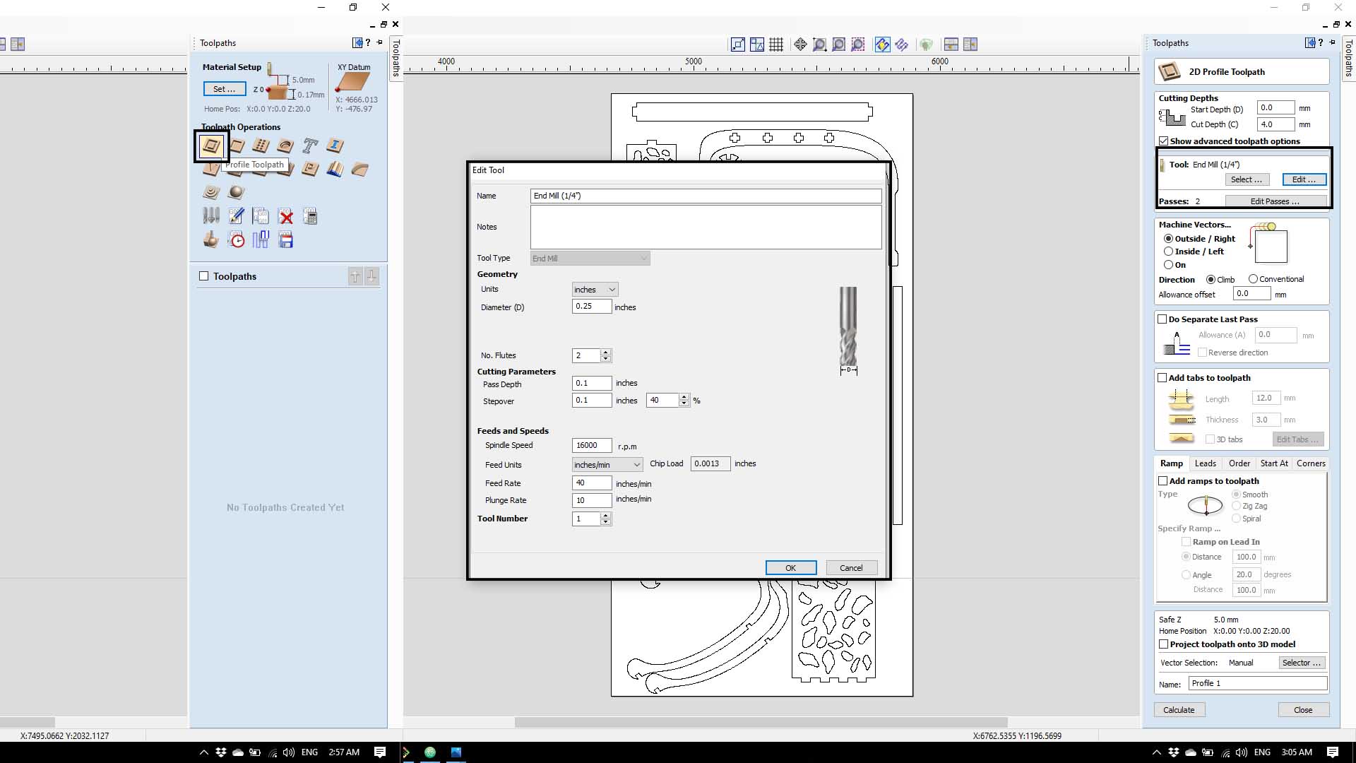
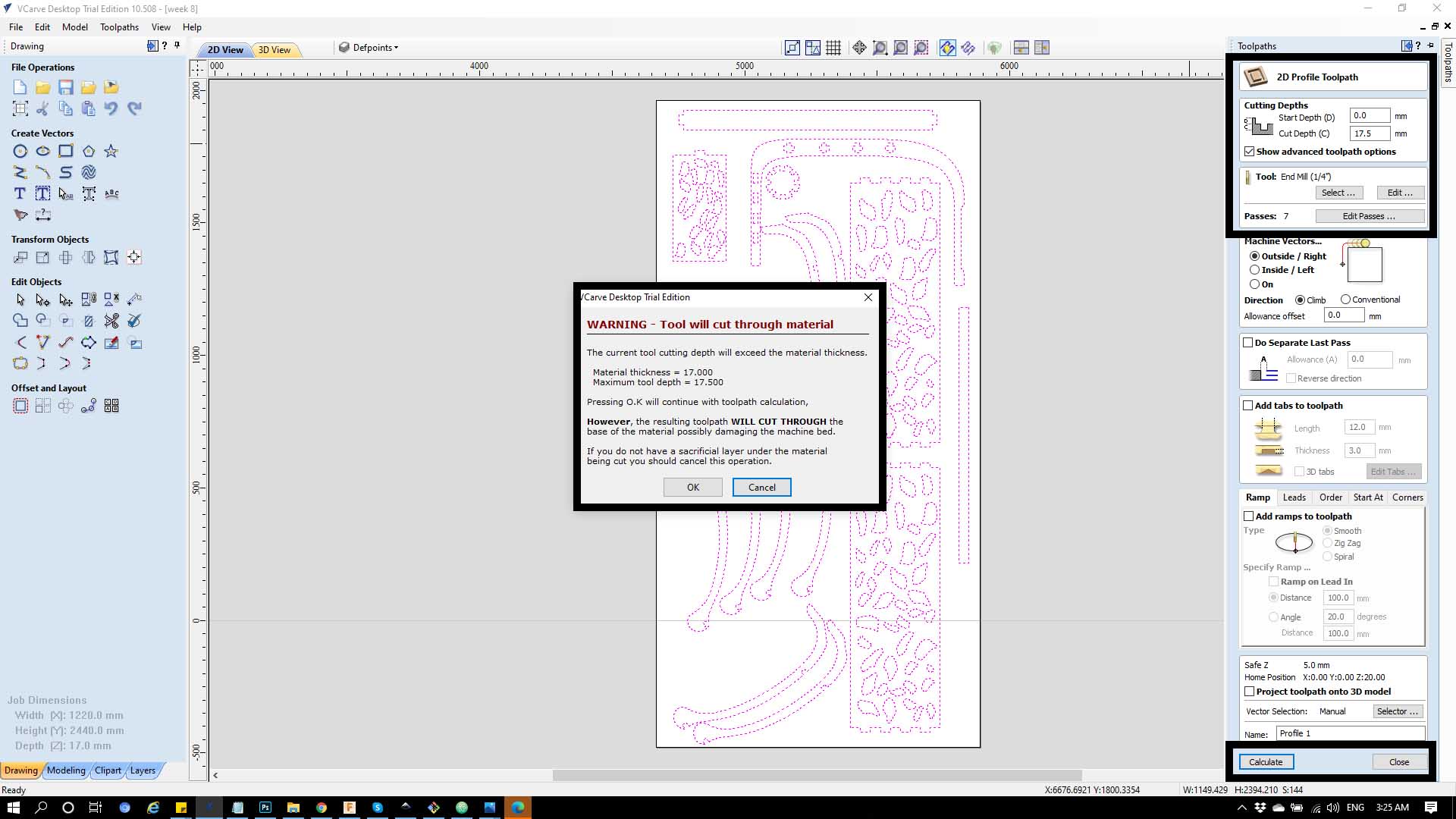
Step 3 : After you choose the mill tool and it is settings you go to the first bar ‘ Cutting Depth’ and change the Cut depth to the the measured deoth of the board + 0.5 to make sure that the board will get cut, Then click on calculate.
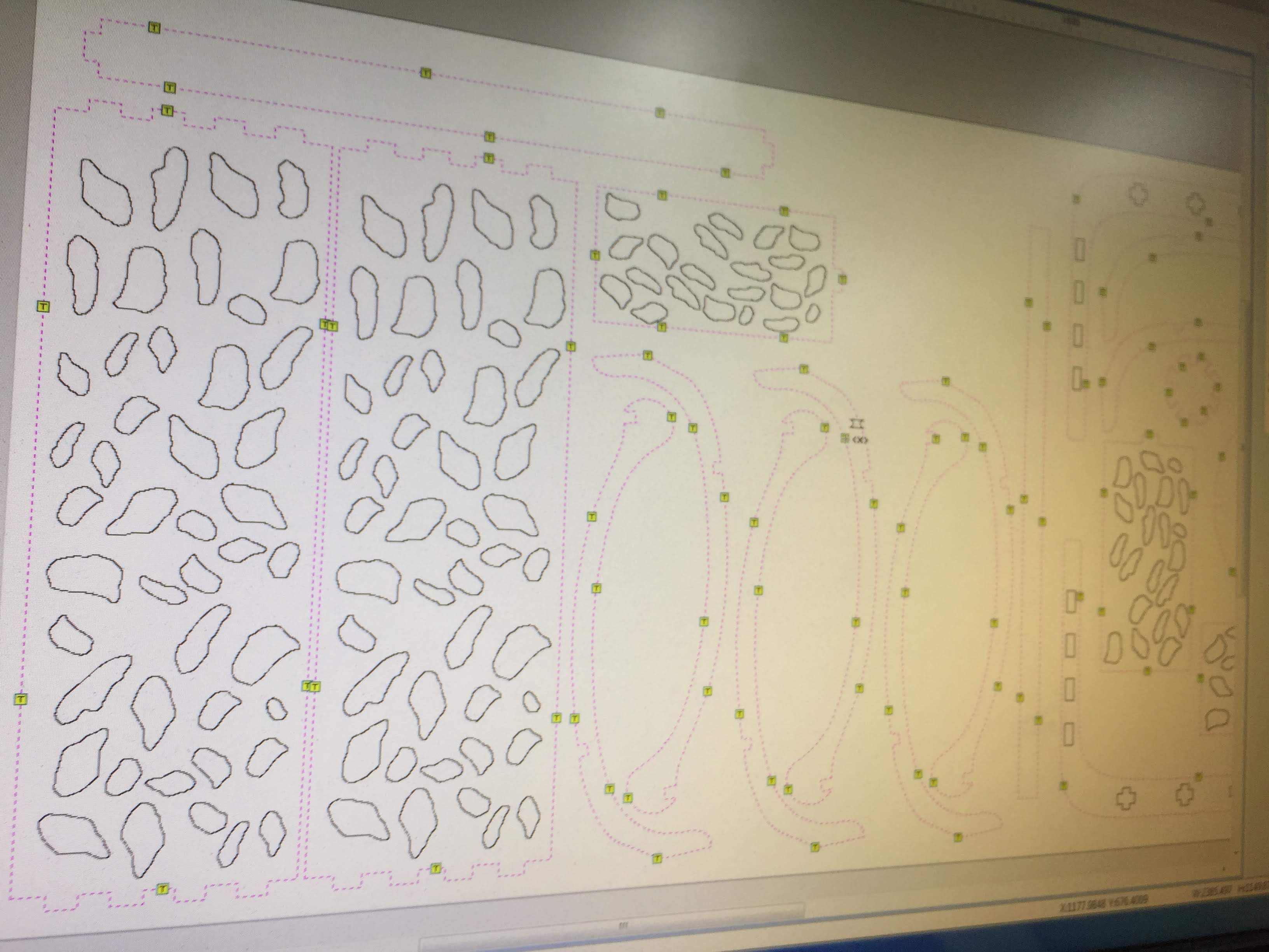
Working with the Tabs
We need to add tabs between objects and board so each part will be kept in place while cutting. First, shift select paths where cuts should be done. Enable “Add tabs to toolpath” and click on “Edit tabs…”. In tabs menu, select “Constant distance between tabs” and change as shown. Click on “Add tabs”. Review tabs and move away from curves using mouse. You can also delete tabs if it was necessary. Click “Close”. Change the “Length” and “Thickness” of tabs and click “Calculate”. Click “Yes” for the warning message.
Placing the board and screw it.
Step 2 : open some holes first to put the screws easily
Step 3 :screw the edges of the board to not let it move during the wood Cutting.
Then i worked with the CNC specialist to set the milling and zero the 3 axis (x,y,z) and save the program in order to send it the ShopBot.
mto setup the machine x and y zero we have to move the machine to the edges , then we zero the 2 axis x,y whoever for the z axis we use the metal blate ( we will place the plate above the board that we are willing to cut) and automated zero and the michine figure it is
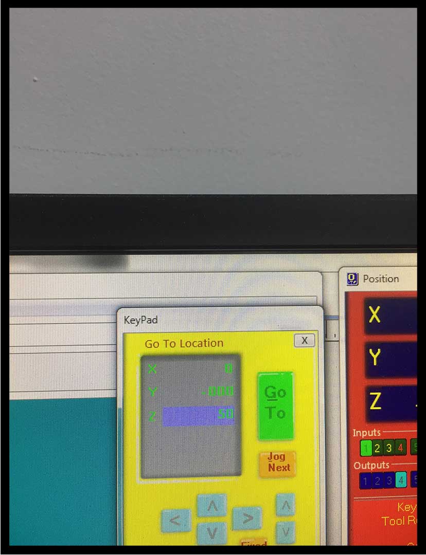
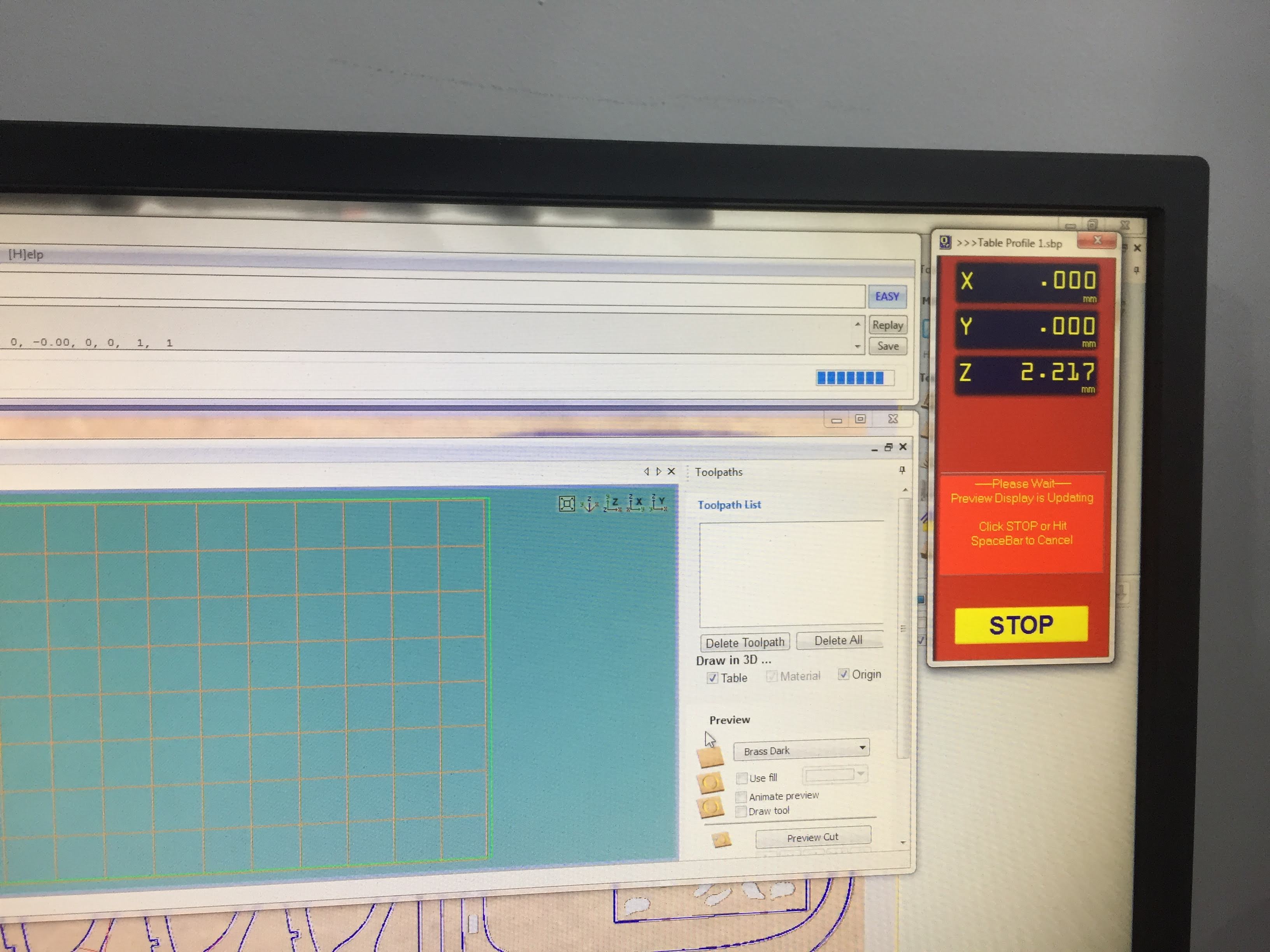
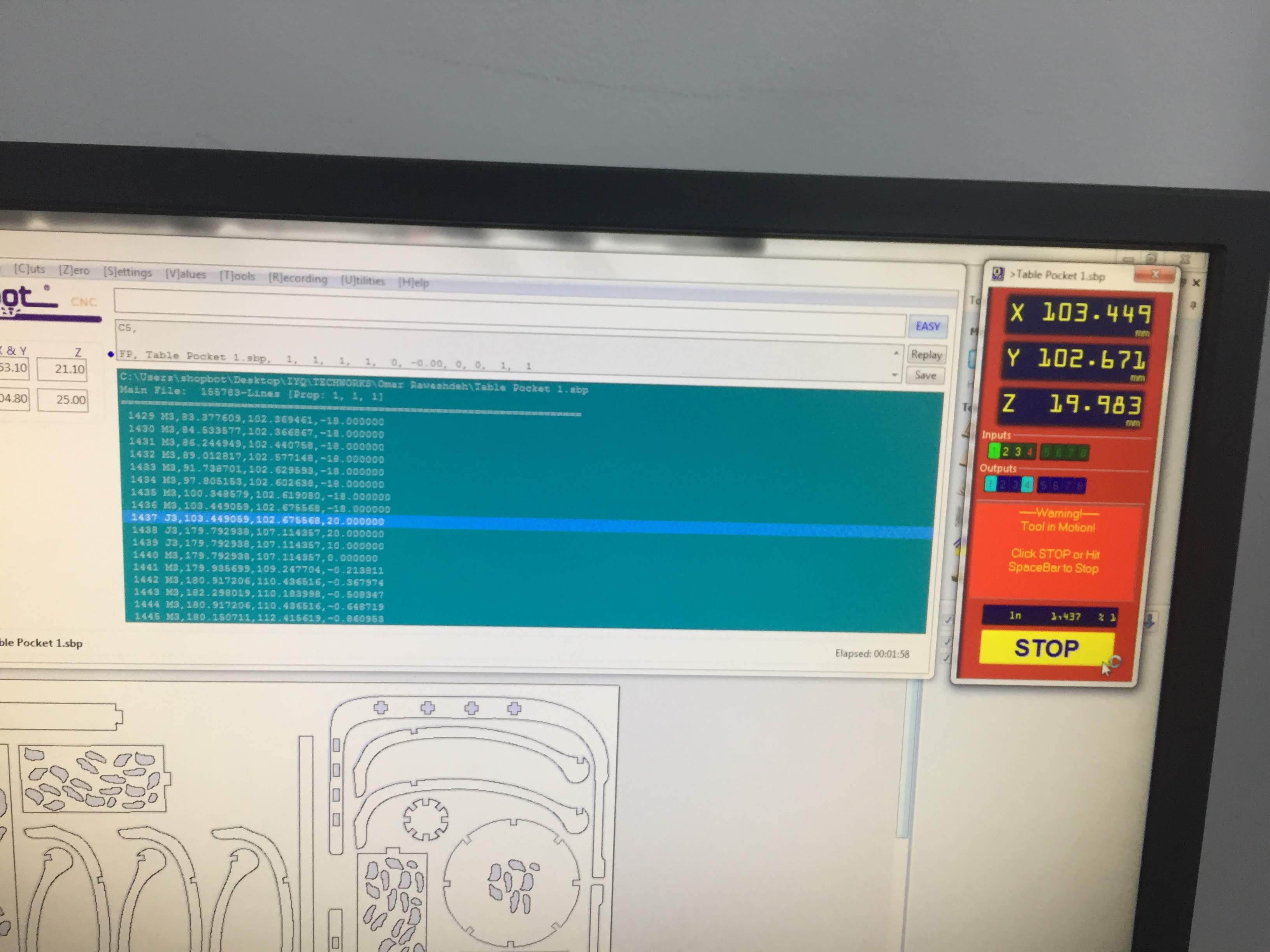
preparing the program
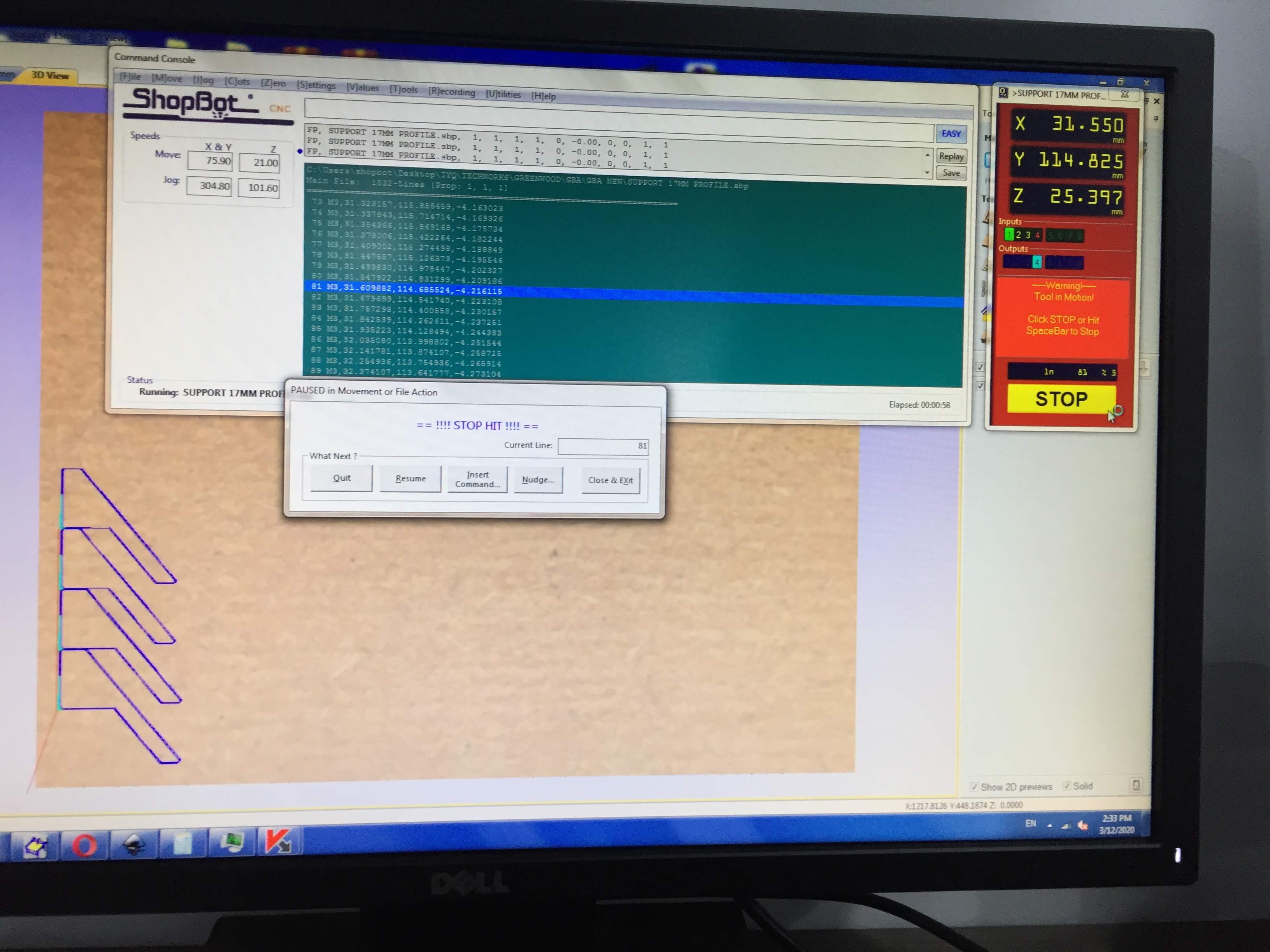
Then press on the green button :
- 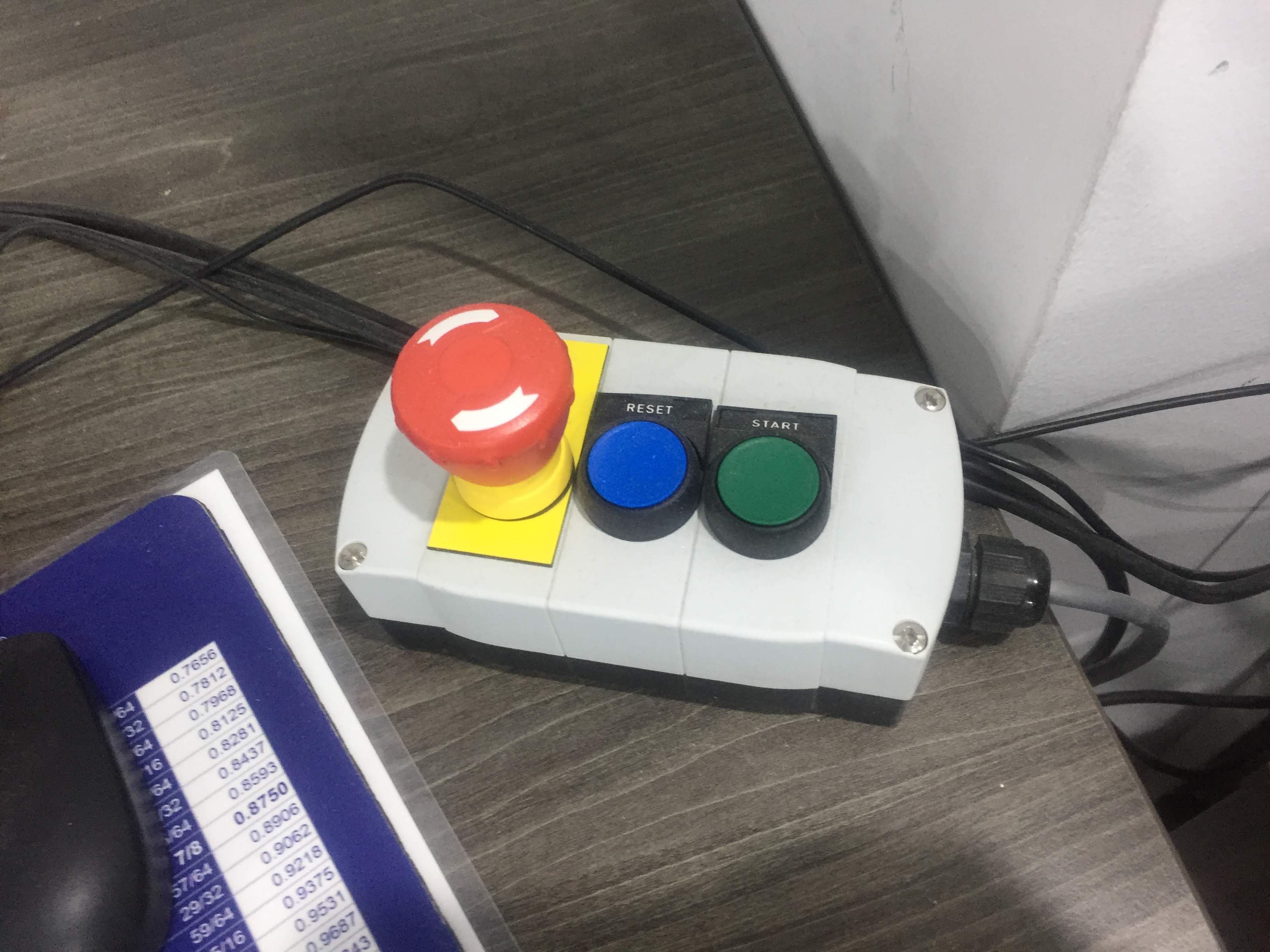
Then this were the last Day before the 3 months Lockdown in my country, so the staff has complete the rest process in order to finish the cut.
Cut the job
After i back to the lab i found the board ready to de-install.