9. Embedded programming
Assignments for week 8
This week we have a group assignment and an individual assignment .
The group assignment for this week is to compare the performance and development workflows .
The individual assignment for this week is to read a microcontroller data sheet program my board to do something, with as many different programming languages and programming environments as possible .
The goal for this week is to try as many programming languages and to get to know how to read a data sheet in order to program a board and in my case the board i am going to program is the one we have made on Week 7 which is the “Hello world” .
Files to download
I have included all the files that you need to download down below and here you can find them directly :
1- ATtiny44 2- Fuse calculator 3- Arduino 4- Toolchain. 5- GNU Make. 6- Avrdude. 7- Zadig.
Group assignment
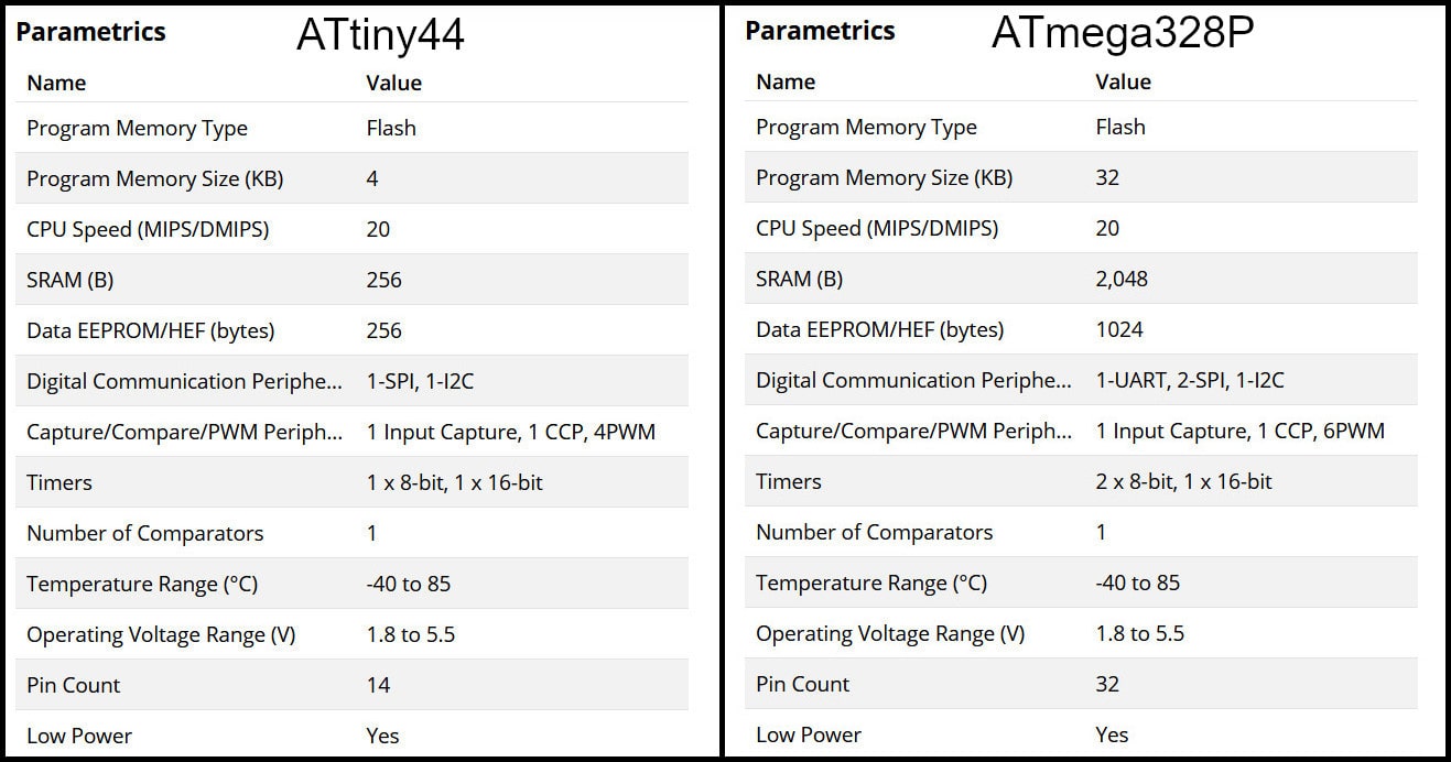
In this part we compared between two AVR families, ATtiny44 from tinyAVR family and ATmega328P from megaAVR family. For ATtiny44 we used avr-dude and FabTinyISP programmer and for ATmega328P we used Arduino UNO board.
Feature Comparison
The table below compares bwteen the two MCUs. “tinyAVR microcontrollers (MCUs) are optimized for applications that require performance, power efficiency and ease of use in a small package”, where “megaAVR microcontrollers (MCUs) are the ideal choice for designs that need some extra muscle. For applications requiring large amounts of code.” Source
Programming ATtiny44 using avr-dude
Write the program in C language using Notepad++ text editor. In the Makefile, define settings like programmer, target MCU, clock rate and lfuse. Using “make” command, build the hex file to be uploaded to target MCU. Connect the FabTinyISP prorammer to USB and ISP cable between programmer and target board. Using the command defined in Makefile “make program-avr-fuses”, program the lfuse to target MCU. Using the command defined in Makefile “make program-avr”, upload the hex file to target MCU.
Programming ATmega328P Using Arduino UNO Board :
Write code using Arduino commands. The target MCU should have the right bootloader burnt to be used on Arduino Uno board. Connect the board to USB and uplad the hex file. To butn a bootloader to a fresh ATmega328P, you can check the built in example from Arduino.
Individual assignment
For the individual assignment i have to read the microcontroller datasheet and to program my board that i have made on Week 06 to do something, with as many programming languages possible also to use the “ISP” that i have made on Week 04 as a programmer .
What is the “ATtiny44” ?
I have used the “ATtiny44” as a microcontroller , So i have to read the ATtiny44 datasheet.
In this week I programmed the board I made in Electronics Design week. The board is based on ATtiny44 and has FTDI port.
Pin configurations And Pin descriptions :
-
the image below shows the pin configurations and the descriptions :
-

| PIN | Function | |
|---|---|---|
| 1 | Gnd | Ground |
| 2 | VCC | Supply voltage |
| 3 | RESET | Reset input. A low level on this pin for longer than the minimum pulse length will generate a reset, even if the clock is not running and provided the reset pin has not been disabled. Shorter pulses are not guaranteed to generate a reset. The reset pin can also be used as a (weak) I/O pin. |
| 4 | Port A (PA7…PA0) | Port A is a 8-bit bi-directional I/O port with internal pull-up resistors (selected for each bit). The Port A output buffers have symmetrical drive characteristics with both high sink and source capability. As inputs, Port A pins that are externally pulled low will source current if the pull-up resistors are activated. The Port A pins are tri-stated when a reset condition becomes active, even if the clock is not running. Port A has alternate functions as analog inputs for the ADC, analog comparator, timer/counter, SPI and pin change interrupt. |
| 5 | Port B (PB3…PB0) | Port B is a 4-bit bi-directional I/O port with internal pull-up resistors (selected for each bit). The Port B output buffers have symmetrical drive characteristics with both high sink and source capability except PB3 which has the RESET capability. To use pin PB3 as an I/O pin, instead of RESET pin, program (‘0’) RSTDISBL fuse. As inputs, Port B pins that are externally pulled low will source current if the pull-up resistors are activated. The Port B pins are tri-stated when a reset condition becomes active, even if the clock is not running. |
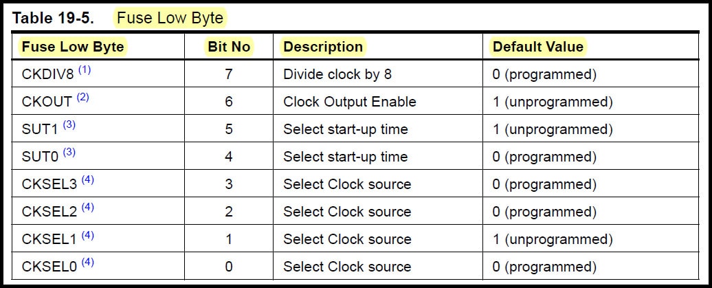
Fuses :
Fuse Low Byte (lfuse) controls clock source, start-up time and, clock division and clock output enabled on CKOUT pin (PB2). lfuse should be programmed only for one time at the beginning, and it is not affected by reprogramming the flash memory.
Programming the Board
Step 1 : Download Arduino.
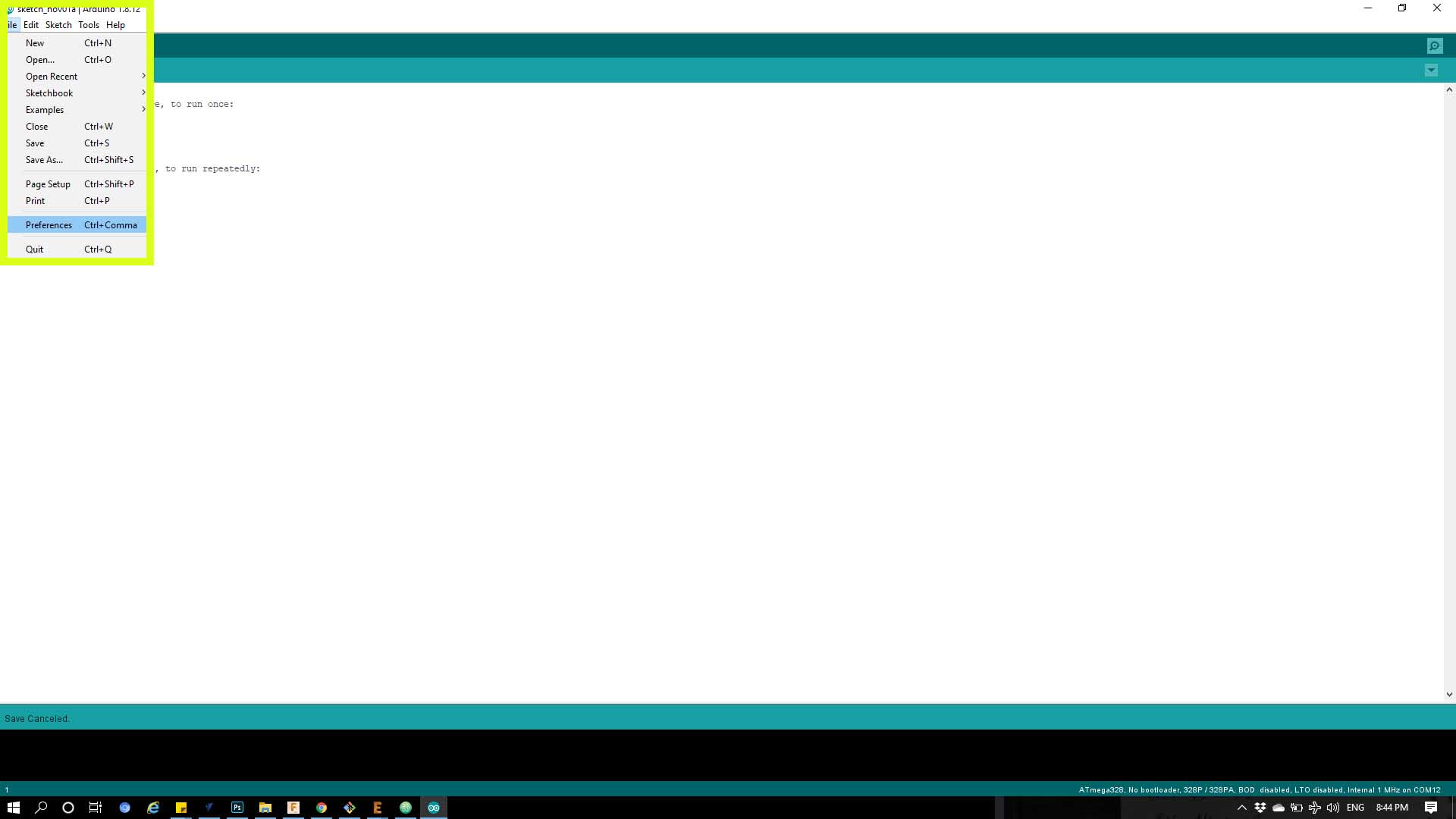
Step 2 : Go and add the library of ATtiny, and that by open Arduino and go to files then Preferences as shown below .
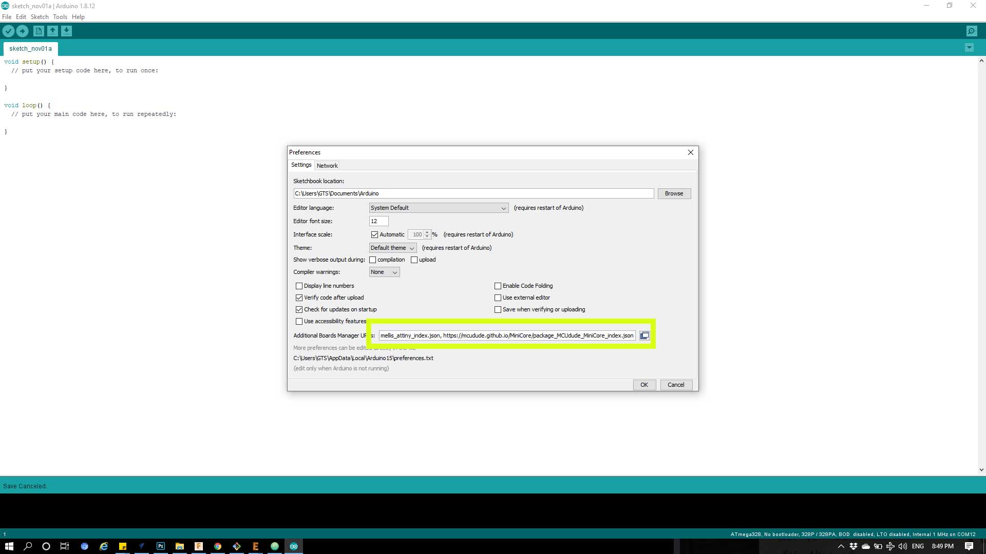
Step 3 : from the drop menu paste the link below in the “Additional board manager URLs”
https://raw.githubusercontent.com/damellis/attiny/ide-1.6.x-boards-manager/package_damellis_attiny_index.json
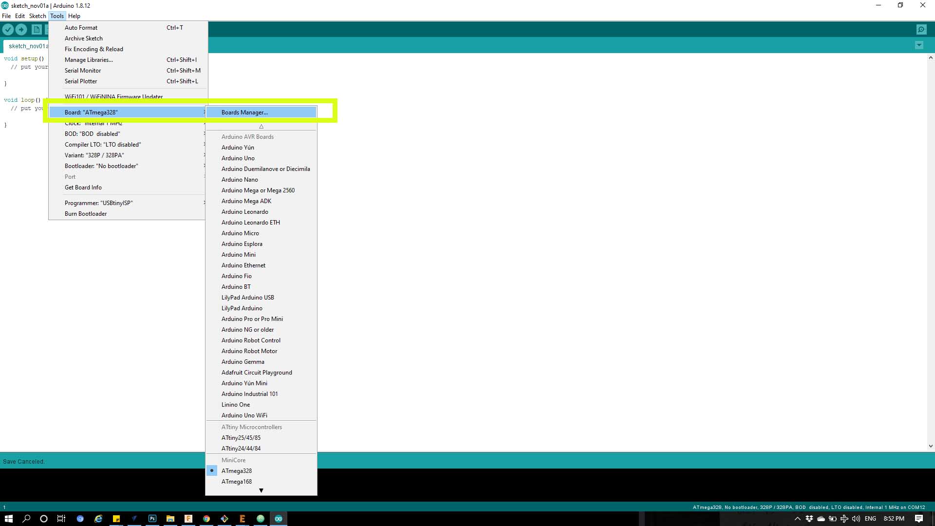
Step 4 : Then click on Tool from the bar above and click on Boards then click on Board manager
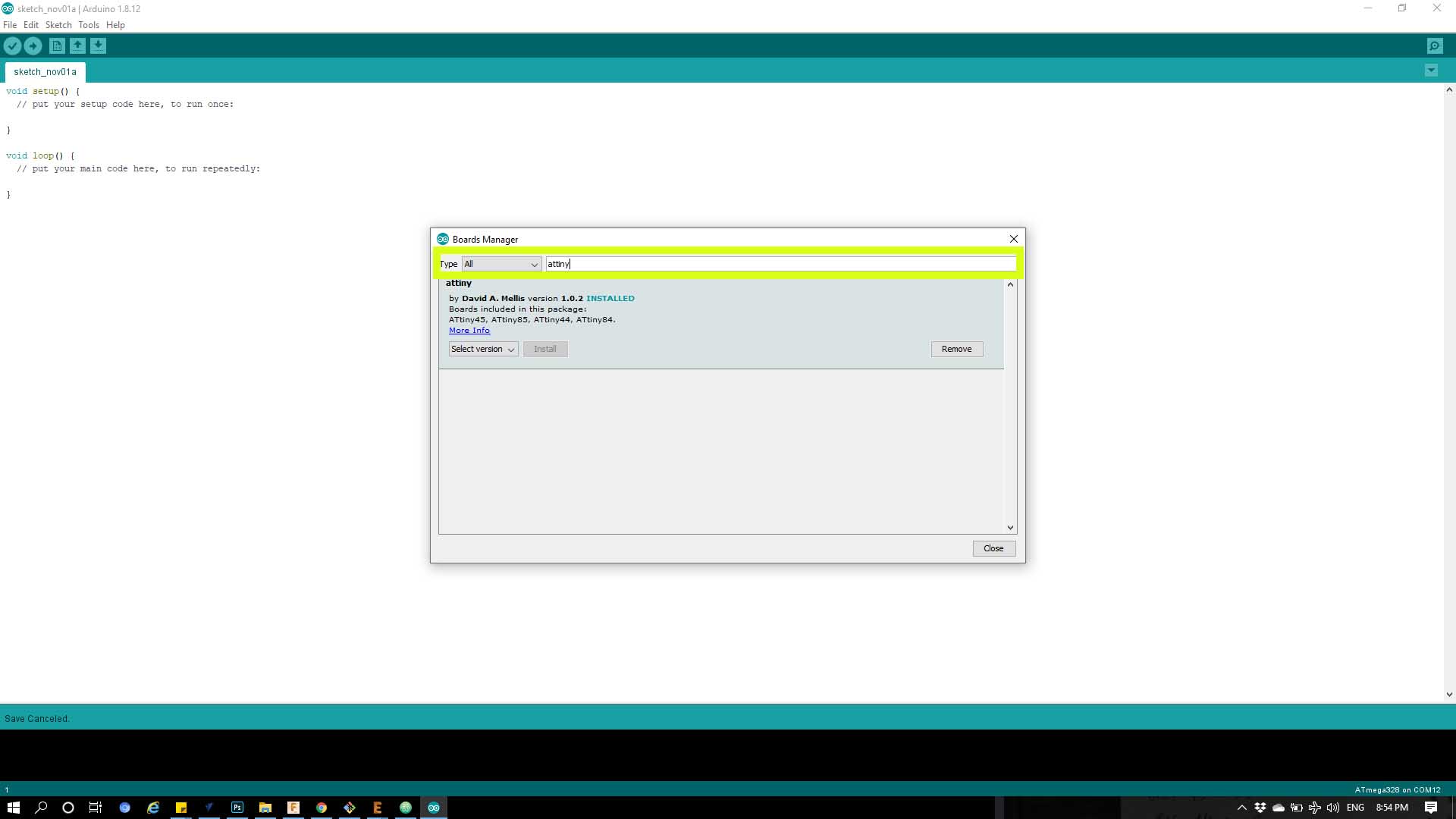
Step 5 : From the drop mneu below write in the search bar ATtiny to be able to download it.
Phase 2 :
Step 1: Download a Toolchain for windows by Download This and register then log in.
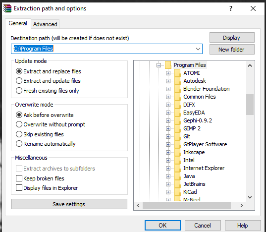
Step 2 : Extract the file [C/programfiles]
Step 3 : Download GNU Make and keep the location of the installing.
Step 4 : Download Avrdude and Extract the file [C/programfiles]
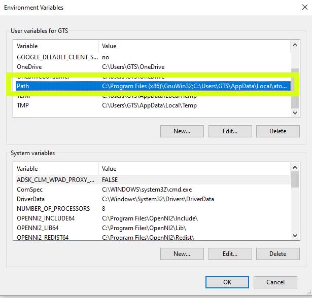
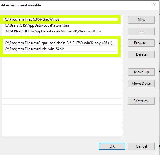
Step 5 : Now work with windows to locate all file we have downloaded, as given below!
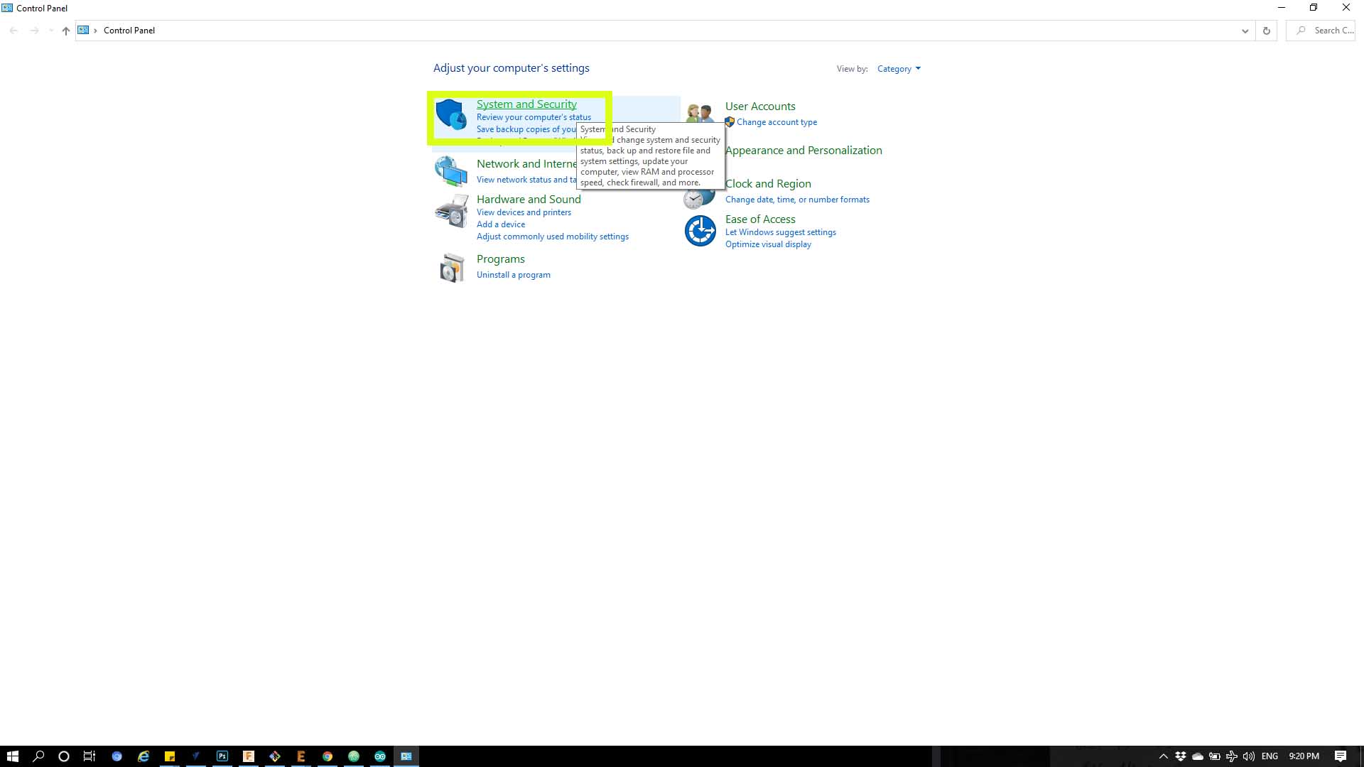
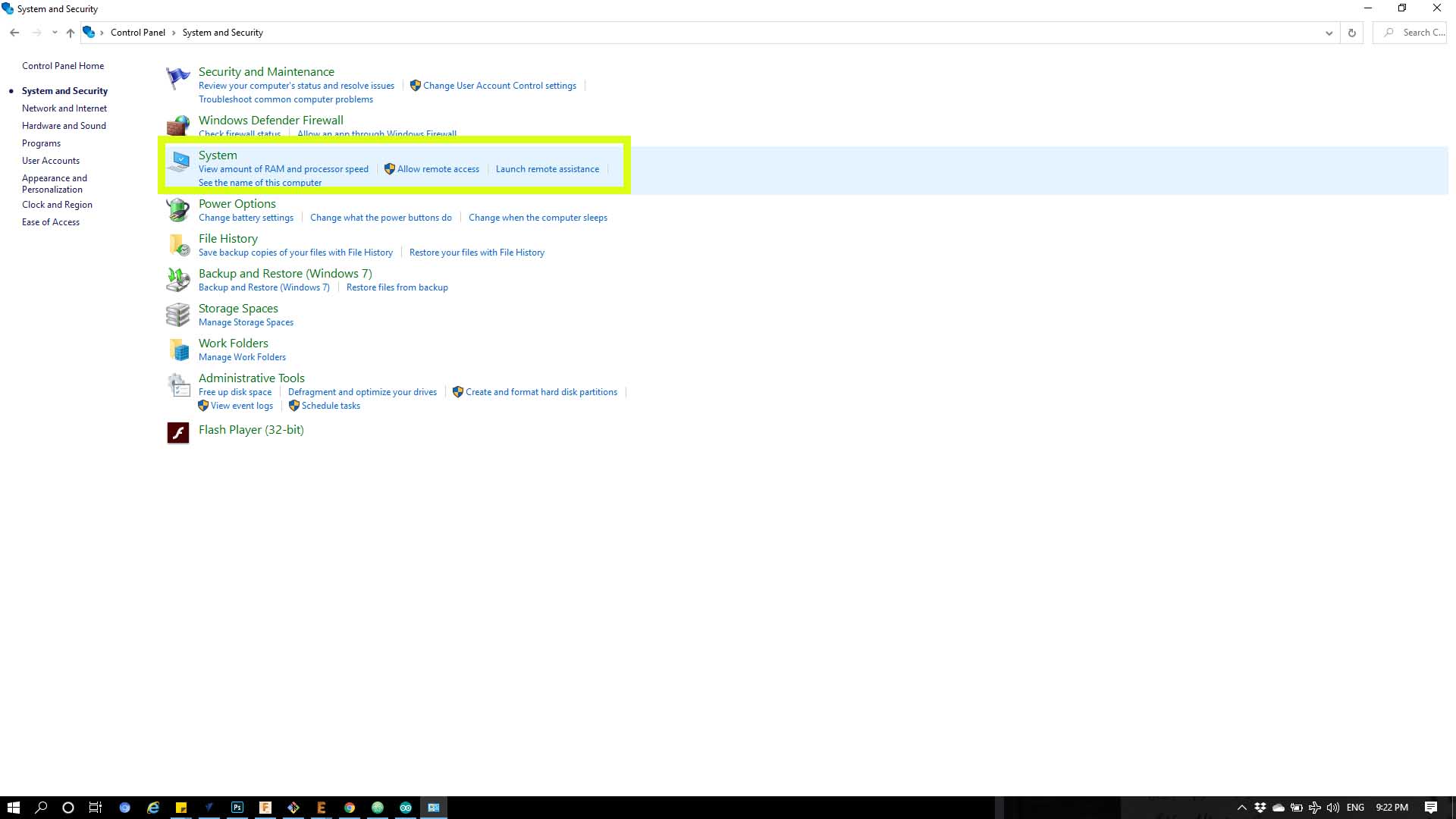
1- Start menu and open the Control Panel
2- Click on System and Security.
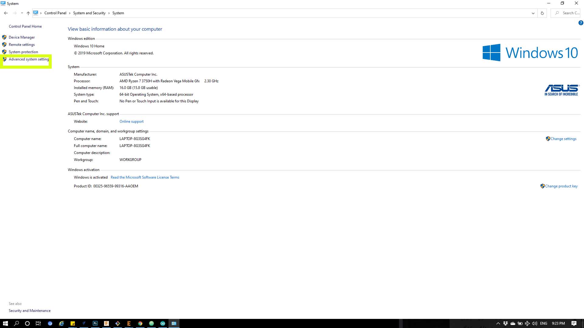
3- choose “Advanced System Settings”.
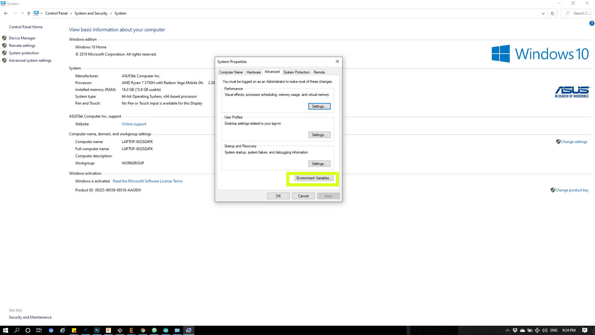
4- click the “Environment Variables”
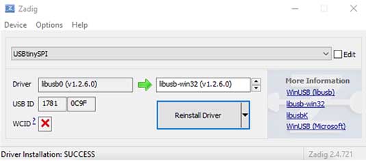
Step 6 : Download this to have driver for the programmer
Programming :
Step 1 : Open Arduino then make sure that the setings below has been changed as shown below.
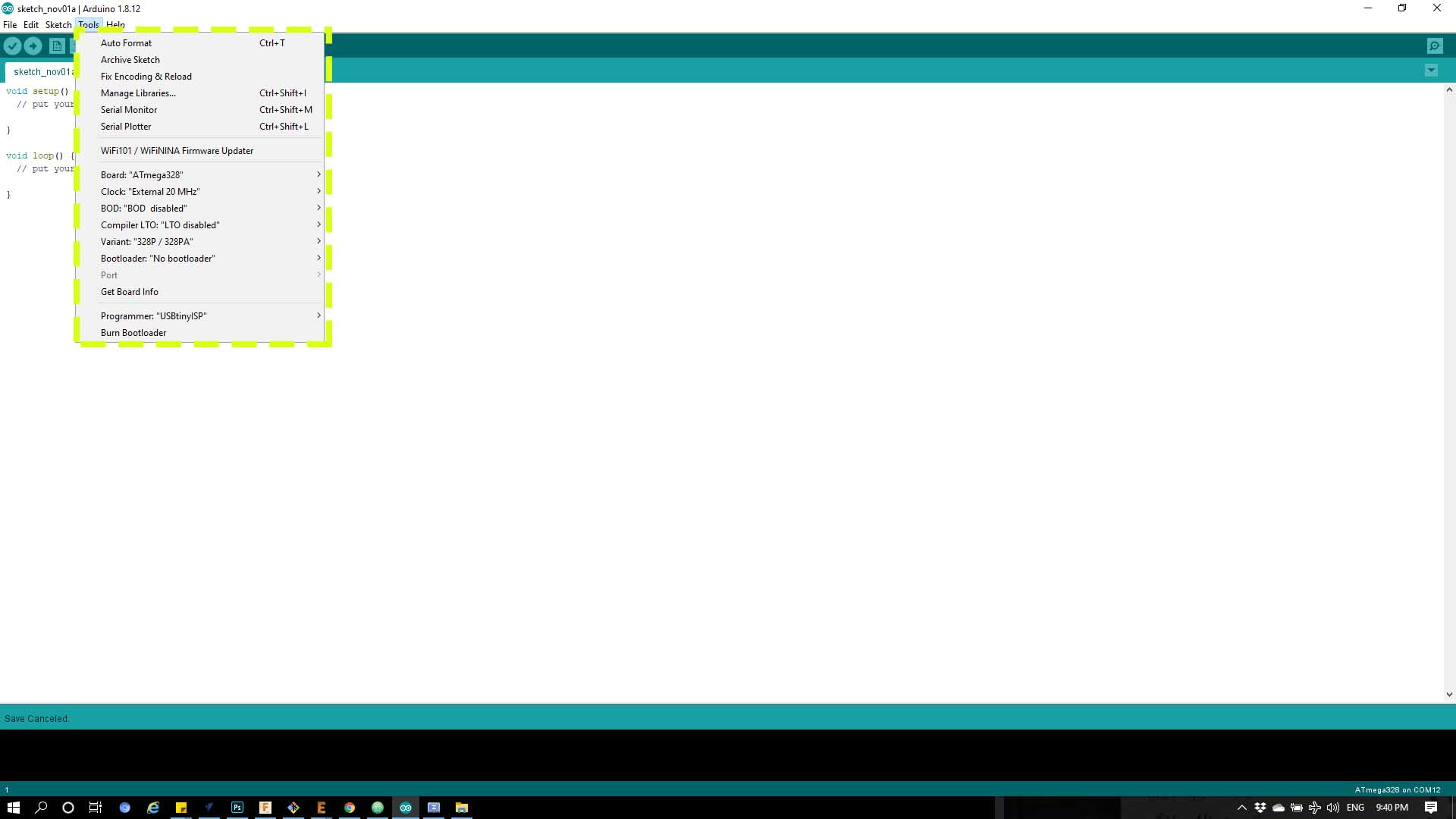
Board : choose “Attiny24/44/84”
Processer : choose “Attiny44” if you are using ATtiny44
Clock : choose “Extended 20 MHZ” for my case because in my board i have added a crystal
Programmer : choose “USBtinyISP”
Hero Shot
Now i have connected my programmer with my board and uploaded a blink code from Arduino IDE to see if everything is working here is the code and here is the board actually working :
Code :
    void setup() {
    // initialize digital pin 2 (PA2) as an output referring to the ATtiny44 datasheet .
    pinMode(2, OUTPUT);
    }

    // the loop function runs over and over again forever
    void loop() {
    digitalWrite(2, HIGH);
    delay(10);
    digitalWrite(2, LOW);
    delay(10);
    }
Hero Shot 2 !
Here i programmed my board to stop blinking if i pressed the button, here is the code and here is a look :
Code :
      const int ledPin =  7;   // As PA7

      // variables will change:
      int buttonState = 0;         // variable for reading the pushbutton status

      void setup() {
        // initialize the LED pin as an output:
        pinMode(ledPin, OUTPUT);
        // initialize the pushbutton pin as an input:
        pinMode(buttonPin, INPUT);
      }

      void loop() {
        // read the state of the pushbutton value:
        buttonState = digitalRead(buttonPin);

        // check if the pushbutton is pressed. If it is, the buttonState is HIGH:
        if (buttonState == HIGH) {
          // turn LED on:
        digitalWrite(7, HIGH);
        delay(10);
        digitalWrite(7, LOW);
        delay(10);
        } else {
          // turn LED off:
          digitalWrite(ledPin, LOW);
        }
      }