4. Computer controlled cutting
This week we have Two assignments to do
1- Group assignment: characterize your lasercutter’s focus, power, speed, rate, kerf, and joint clearance
2- Individual assignment: - Cut something on the vinylcutter - Design, lasercut, and document a parametric construction kit, - Accounting for the lasercutter kerf!
Group assignment
For group assignments we tested two different machines and we worked on the machines to get a physical test for each material such as ( Cardboard, MDF, plywood and acrylic).
1- Vinyl Cutter
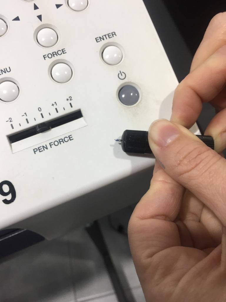
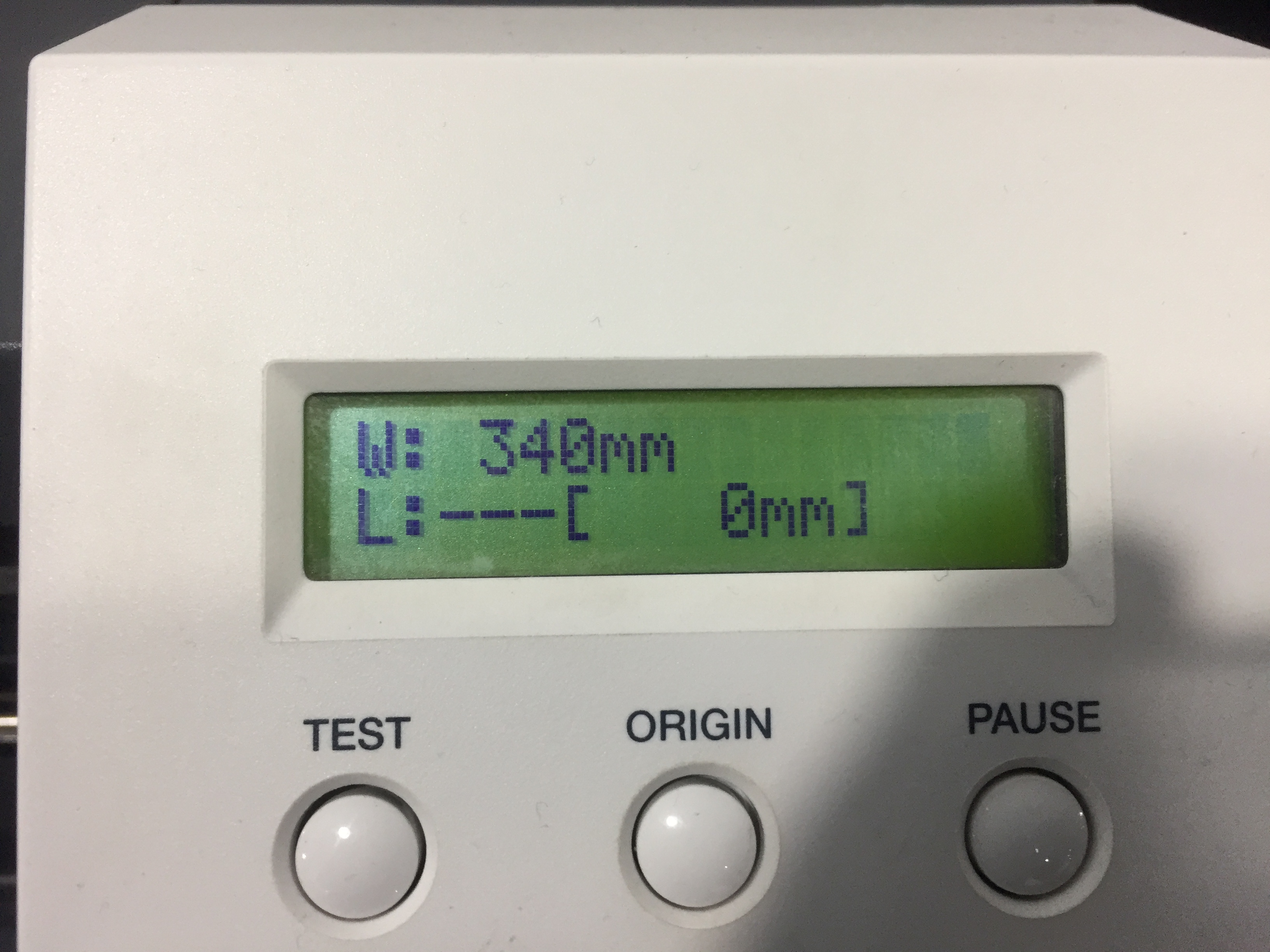
      ROLAND GX-24.
      Software: Inkscape + Driver of Roland
      Maximum cutting area: 584 x 24998 mm
      Cutting speed: 10-50 mm/s
      Settings:
      Textile Vinyl: Speed: 15 cm/s / Force: 90gf
The machine’s parts
1- Cutting blade:
The cutting blade has different levels for cutting and you can change it by push it from the back end of the piece.
- To get the best quality of cutting the blade should be sharp as shown in the picture.
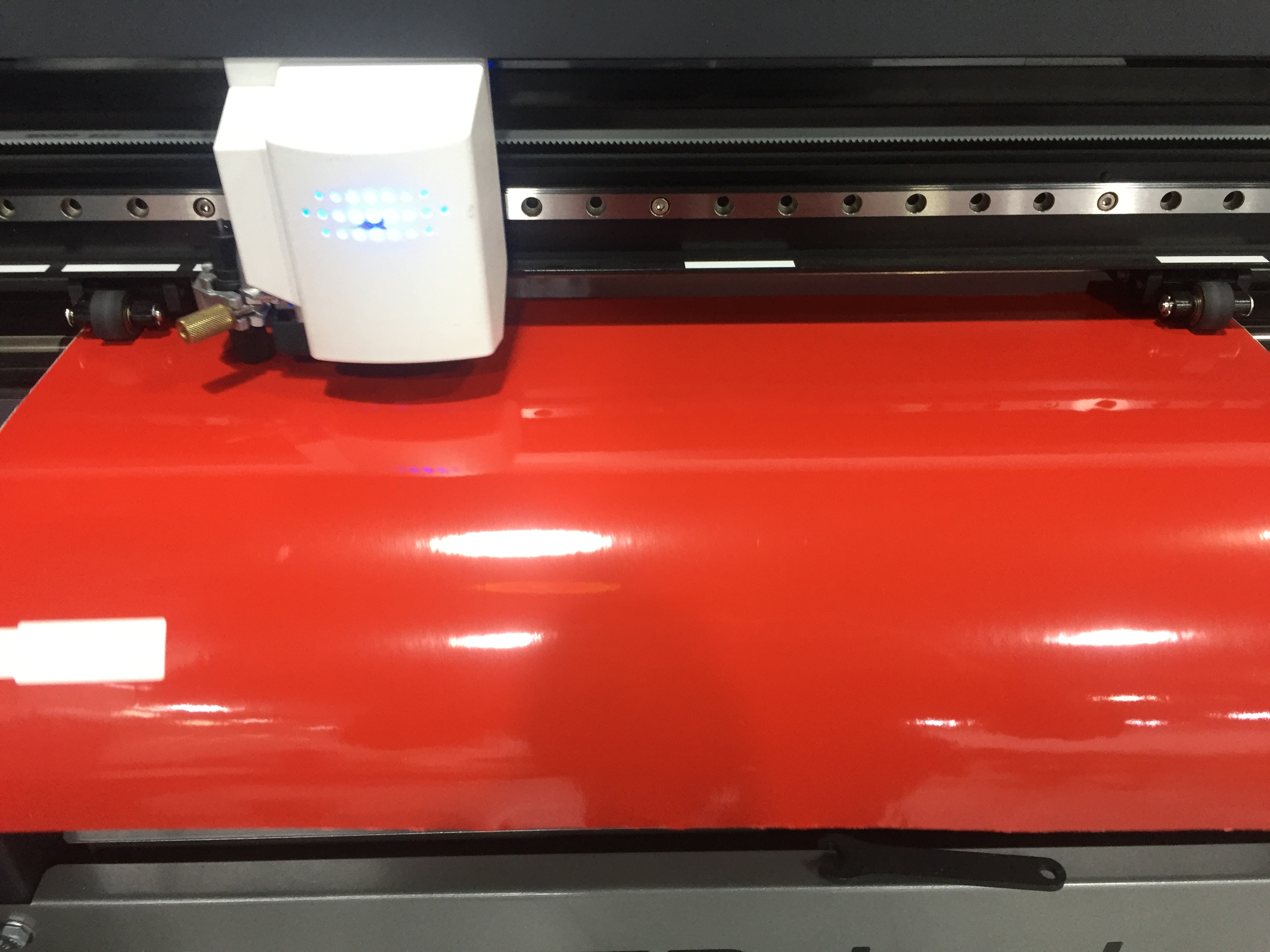
2- The roll place:
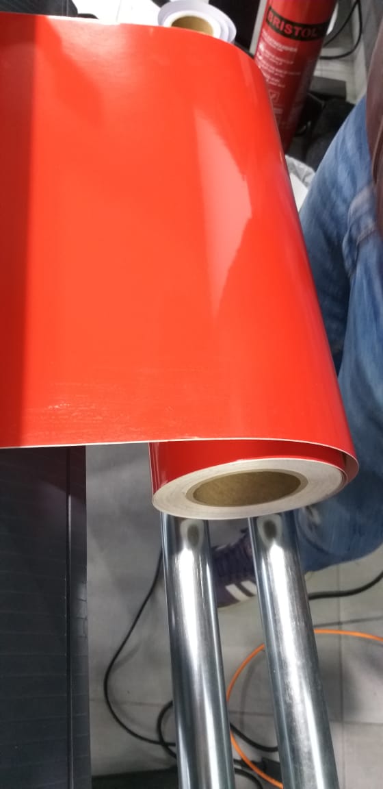
The vinyl roll is placed on the back of the machine, and it can be changed manually to a different roll based on the color you want.
Then you insert the roll manually inside the machine as shown below:

After inserts the roll you drag the rollers that shown in the picture to as a border for the work space then you pull the handle to close it.
Then you press enter, the blade will measure the width of the roll.
- We tested the sharpness and the depth of the blade to make sure that the blade will not cut the white layer of the roll.

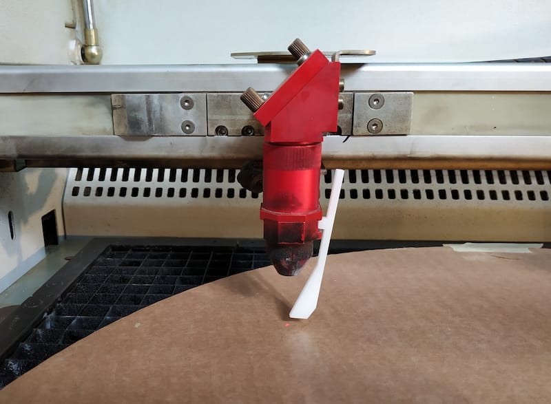
Laser Cutting
LASER CUTTER:
Files : - Laser kit
Model: trotec speedy 400.
We worked on all steps from starting the machine to engraving and cutting a sample on cardboard, MDF, plywood and acrylic.
Safety First!:
We have tested different materials and different tests:
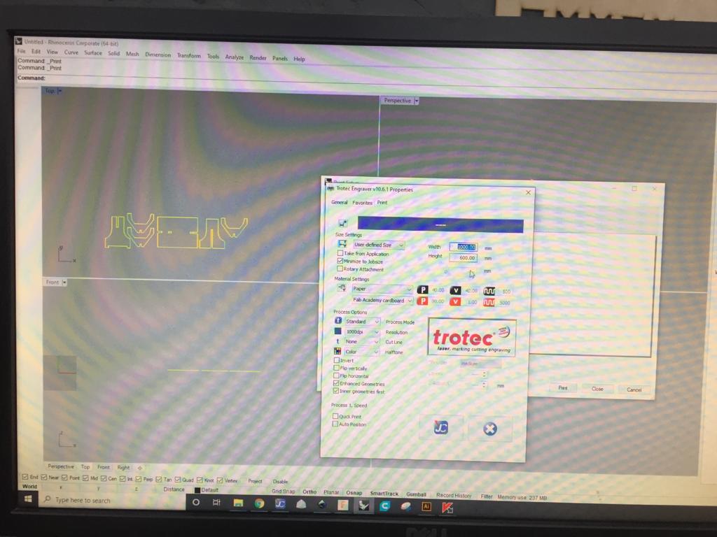
The jobs are run from a computer next to it, through Rhinoceros, print driver and controller.
The software is basically used for importing files and assigning colors and layers. This step is important, especially if you are going to work with more than one work operation.
-
Then After setting the layers and sending the print command, the job goes to the controller.
-
Add the material.
-
Focus the machine.
Then were done Tests.
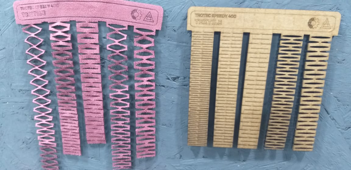
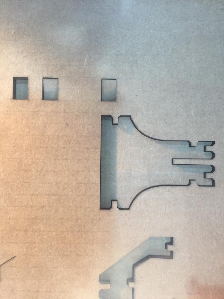
- The best results were 3.9 mm and 4.0mm gaps for cardboard ..
2 - Individual assignment
VINYL CUTTER
Files :
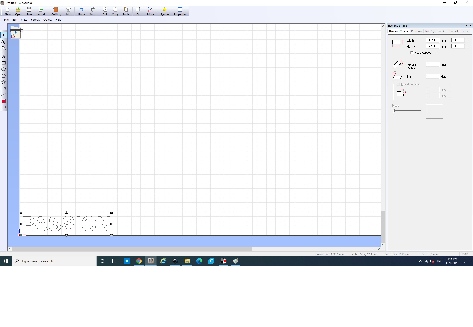
I have used v-cut to design the sticker as shown below:

Then click on the Text command in order to start write whatever you want as shown below :
then i have scaled down the text size to 16*9 cm
then click on ‘file’ then click on cutting ‘command’
The from the dropped down menu the defult setting will will be ready to be used
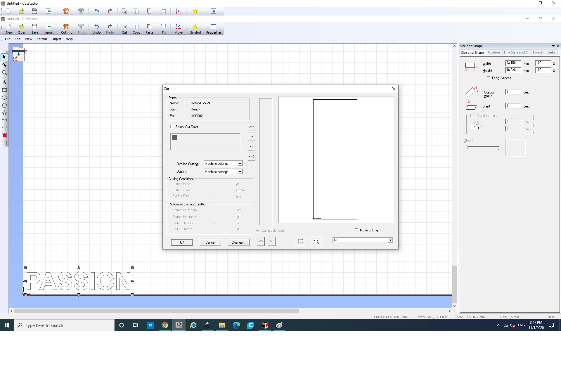
Then press ‘OK’
- Step 2: used a red roll and put it inside the cutter.

- Step 3: The machine cut the sticker with the same settings on the machine.
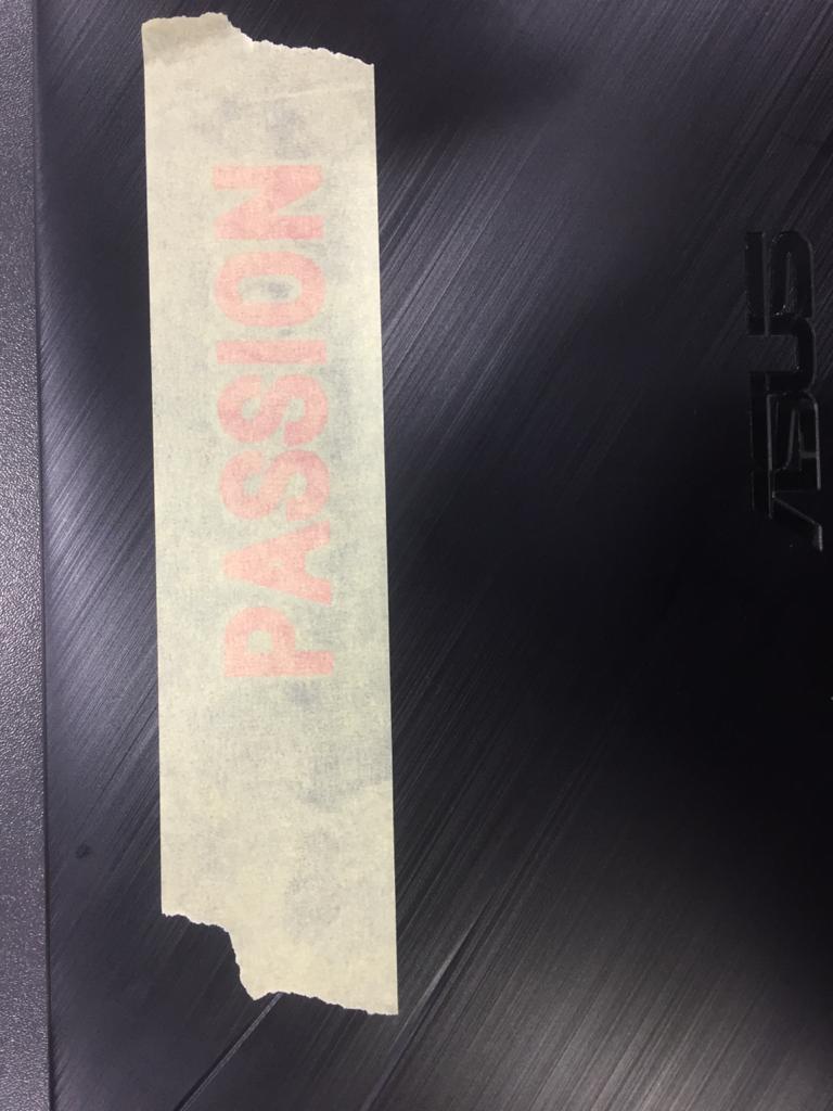
- Step 4 : Got the cut ready, then i put a scotch tape on the cut.
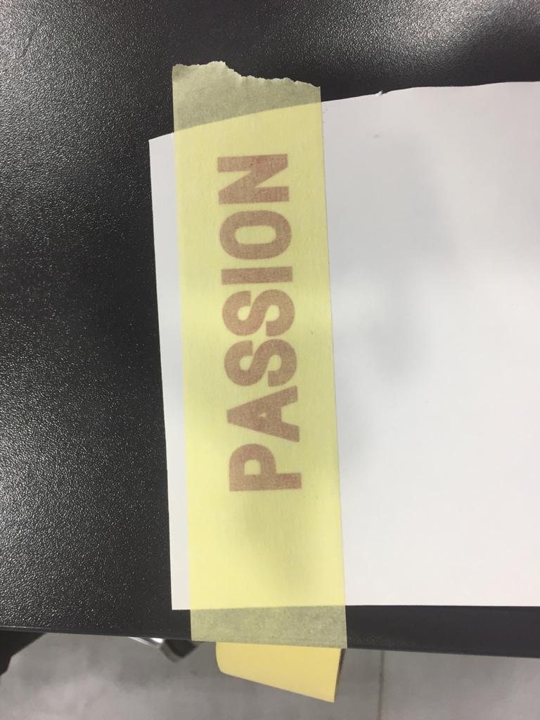
Step 5 :
Stick the sticker on the laptop then remove the tape.
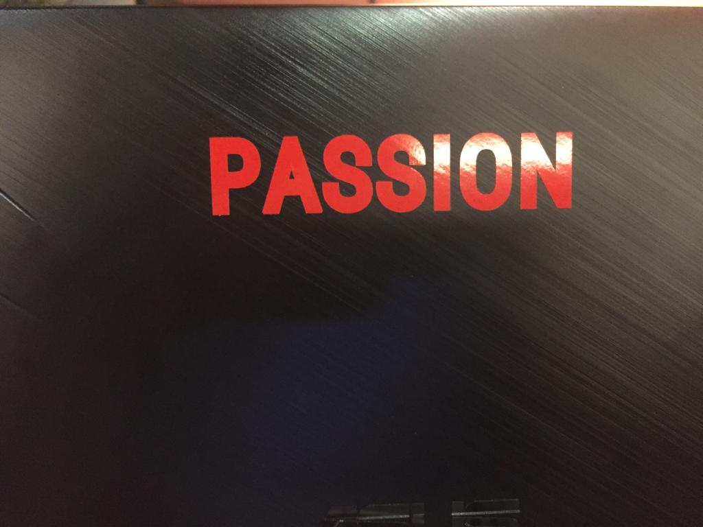
HERO SHOT !
LAPTOP COVER
LASER CUTTER
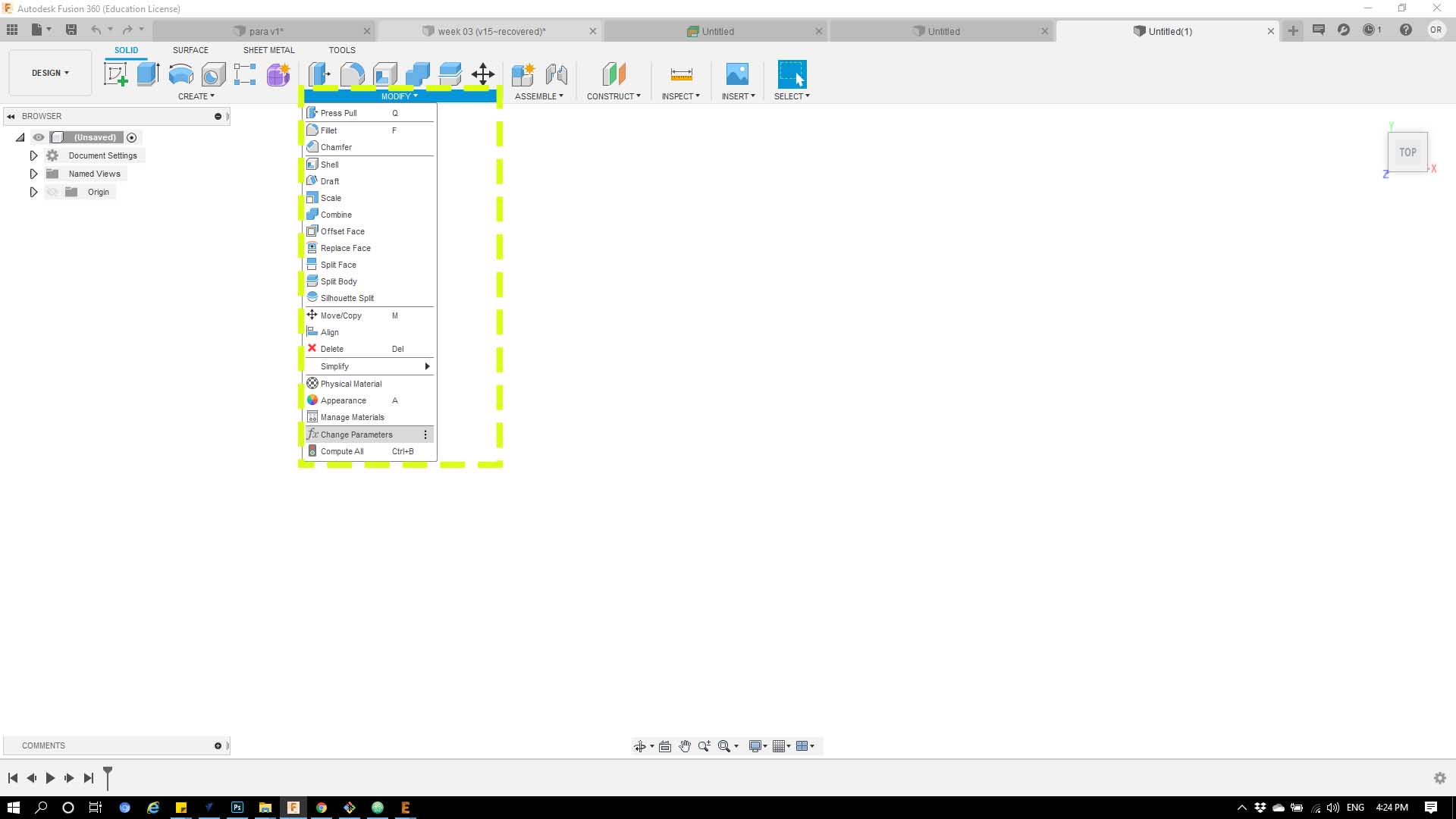
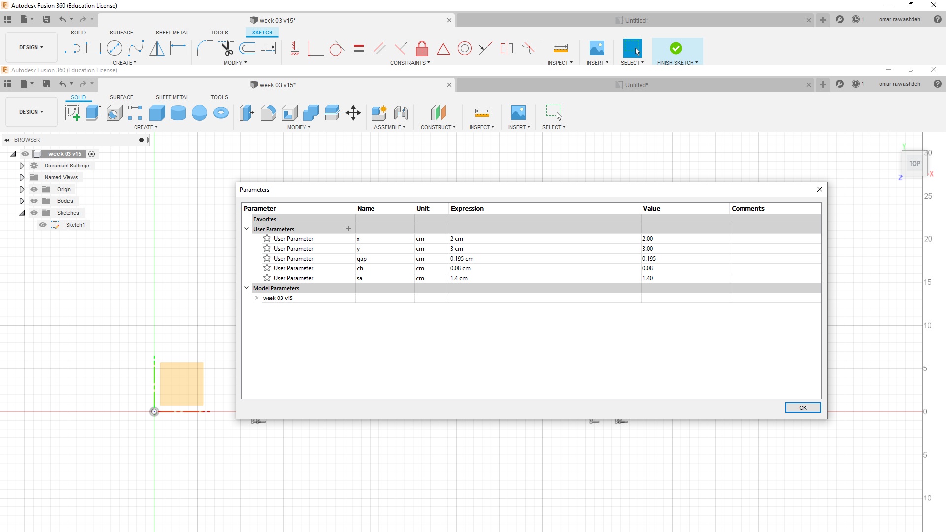
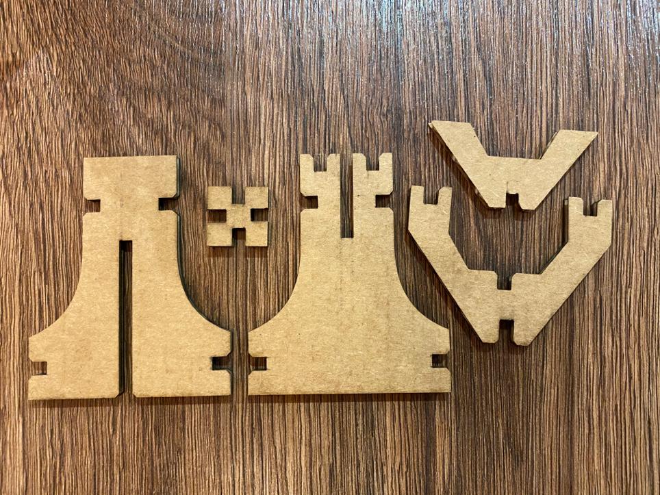
To make the design I used Fusion 360. It is very important to do a Parametric Design, because you do not know the exact tolerance and changing it with only one number is really useful. A parametric design is a design based on the defenition of the parameters. Then it is all mathematical, so if you wanted to change your design is as simple as changing those numbers. It is really usefull to adjust tolerances, but you have to be really carefull. I did all the design paramaetric, so all the dimesnions where parameters, but I did a mistake, and I regret it afterwards… I did some simetry with fusion and the mesurments weren’t saved, so I had to sand some joints. Also be carefull, because if there are a lot of parameters fusion can show some errors and collapse.
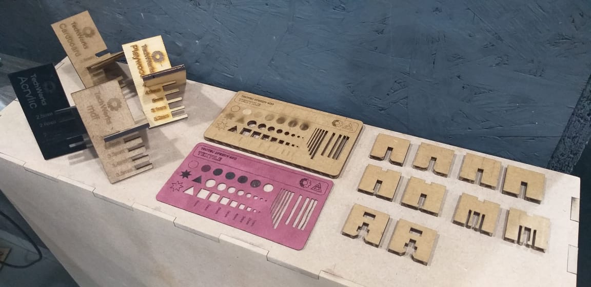
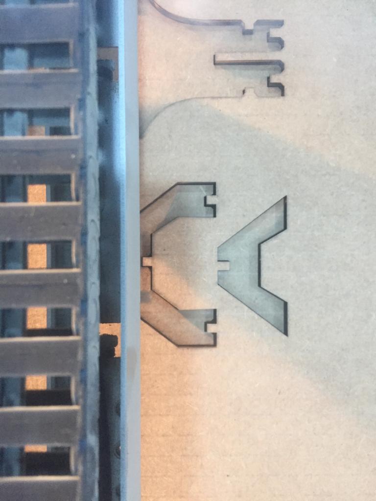
The design was made of 5 pieces, The idea is that the strips join one base per each side creating a parallel life’s Tree.

- Fusion 360 design:
- Parameters i have used in the design:
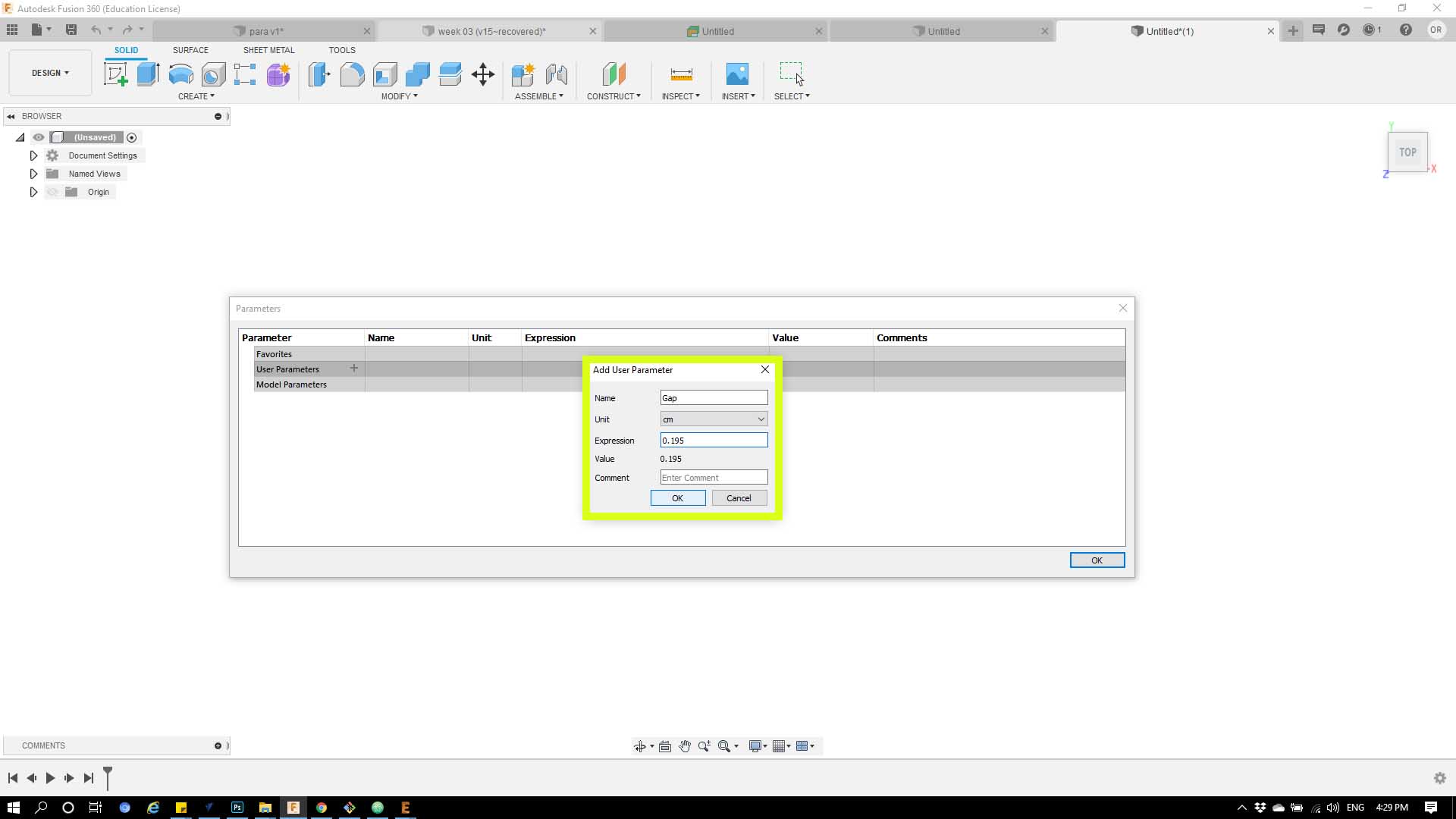
Step 1 : From the commands bar choose ‘Modify’ then from the list choose ‘Change parameters’ as shown below.
Step 2: from the menu will be shown click on ‘User parameters’
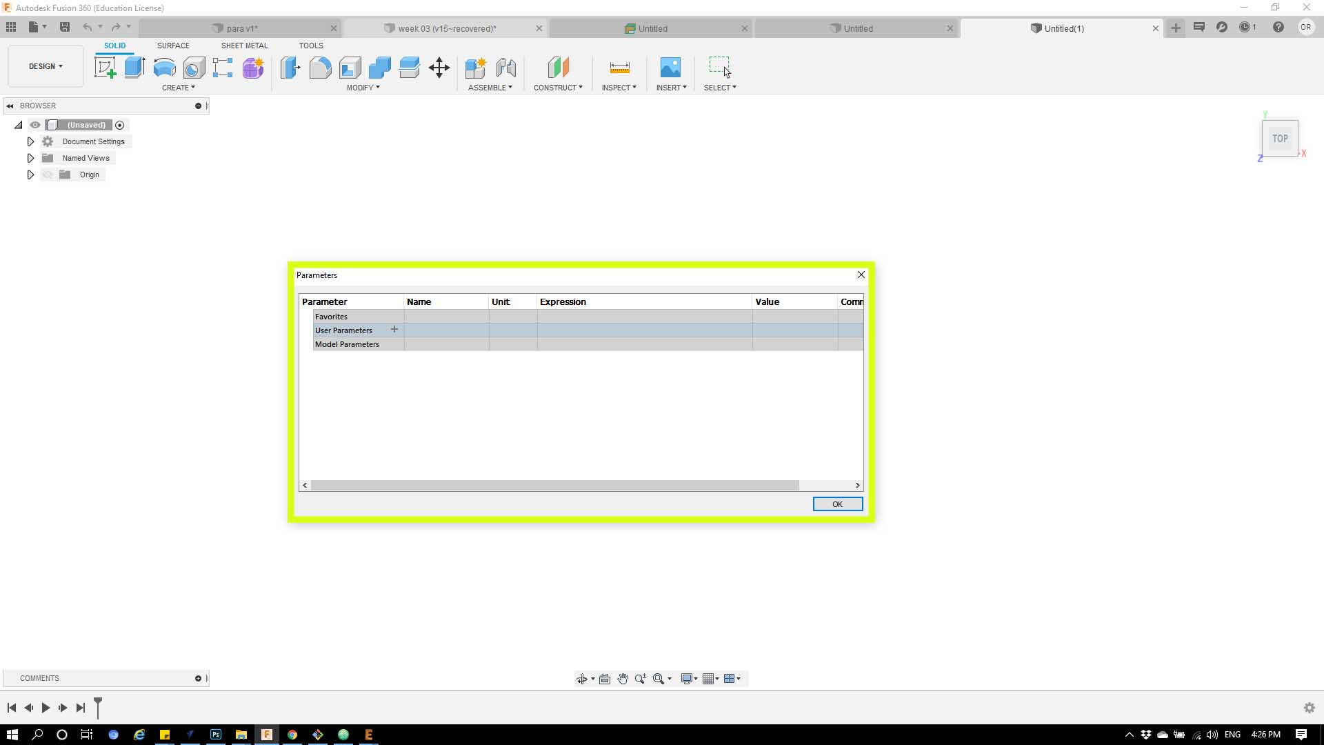
Step 3 : the drop menu will give you the option the name the parameter and give it a value
Then i exported the file to Dxf to import in to rhino, i joined all pieces then from file you choose print, directly the sheet will transformed to job converter.
After this the machine will start cut :
    Cut:
    Power: 60%, Speed: 01%, and frequency: 5000
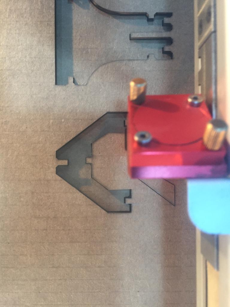
-The final result
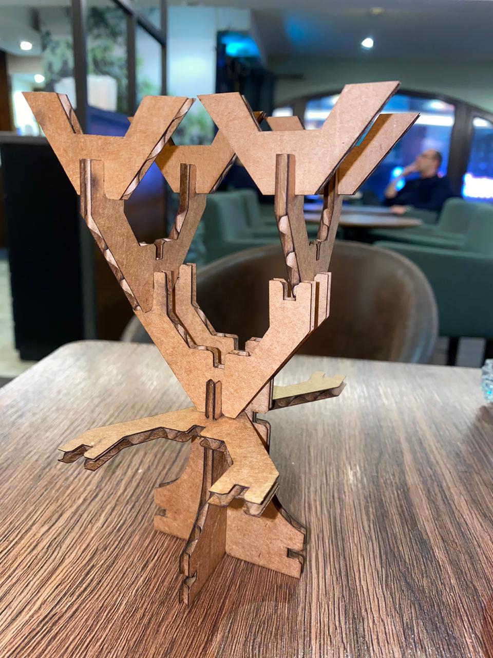
Kit construction
