Project documentation
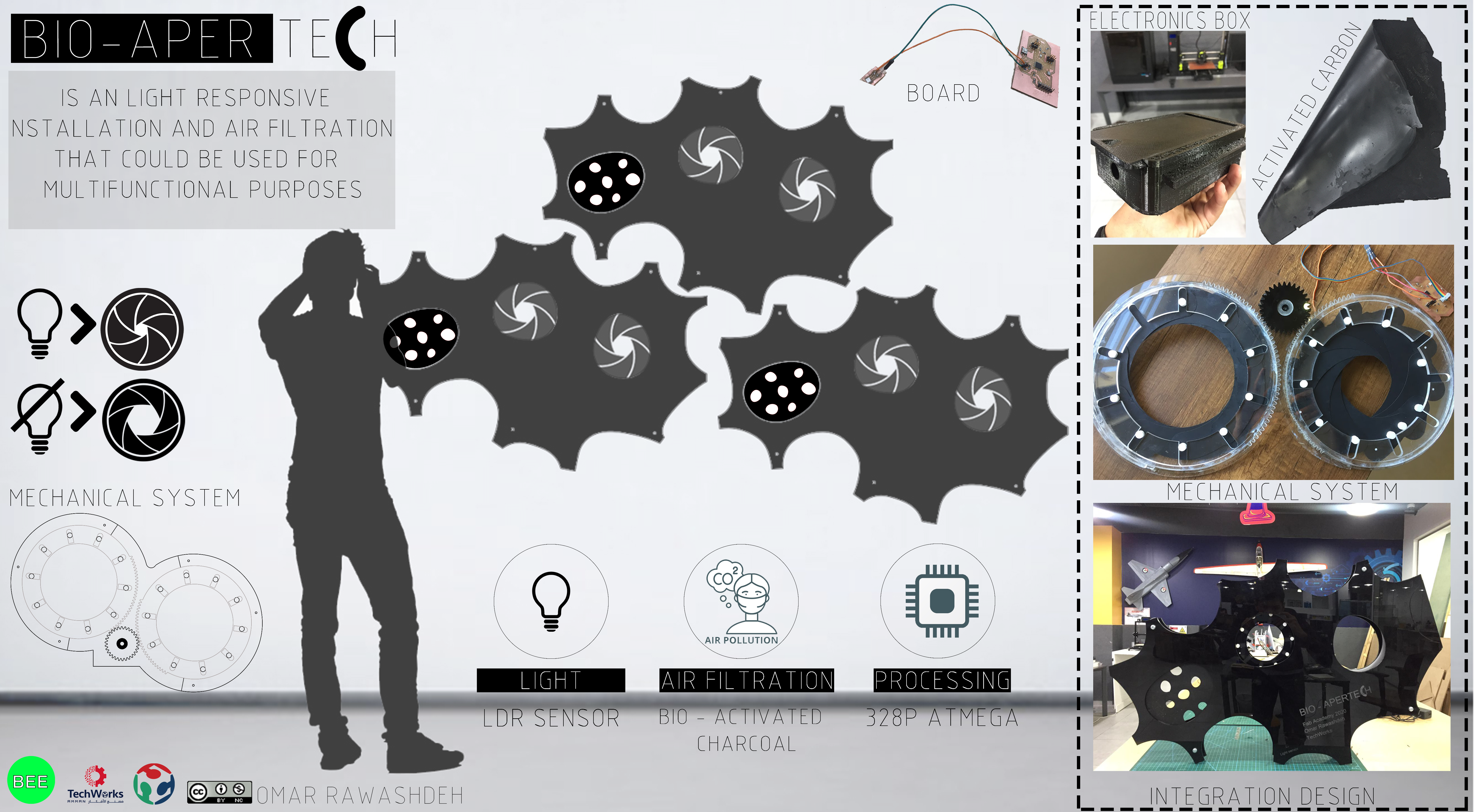
The project is A light responsive installation and it work with different light intensity such as phone light or controlled room light intensity and the future improvement is to make respond to the sun Light.
Inspiration
- Hexi - responsive wall
Hexi - responsive wall from Thibaut Sld on Vimeo.
-
Aperture facade installation
Tobias Becker’s Breathing Skins Project Based on the concept of biomimicry, the technology is inspired by organic skins that adjust their permeability to control the necessary flow of light, matter and temperature between the inside and the outside. In addition to these performative benefits, the constantly changing appearance of these façades provides a rich interplay between the exterior natural environment and interior living spaces.
Research
[Firefly experiments]
2D and 3D Modeling software’s
Rhino + Grasshopper (Firefly)
Fusion
Files
The components
| INPUT | OUTPUT |
|---|---|
| Light sensor (PT15-21C/TR8) | Servo motor |
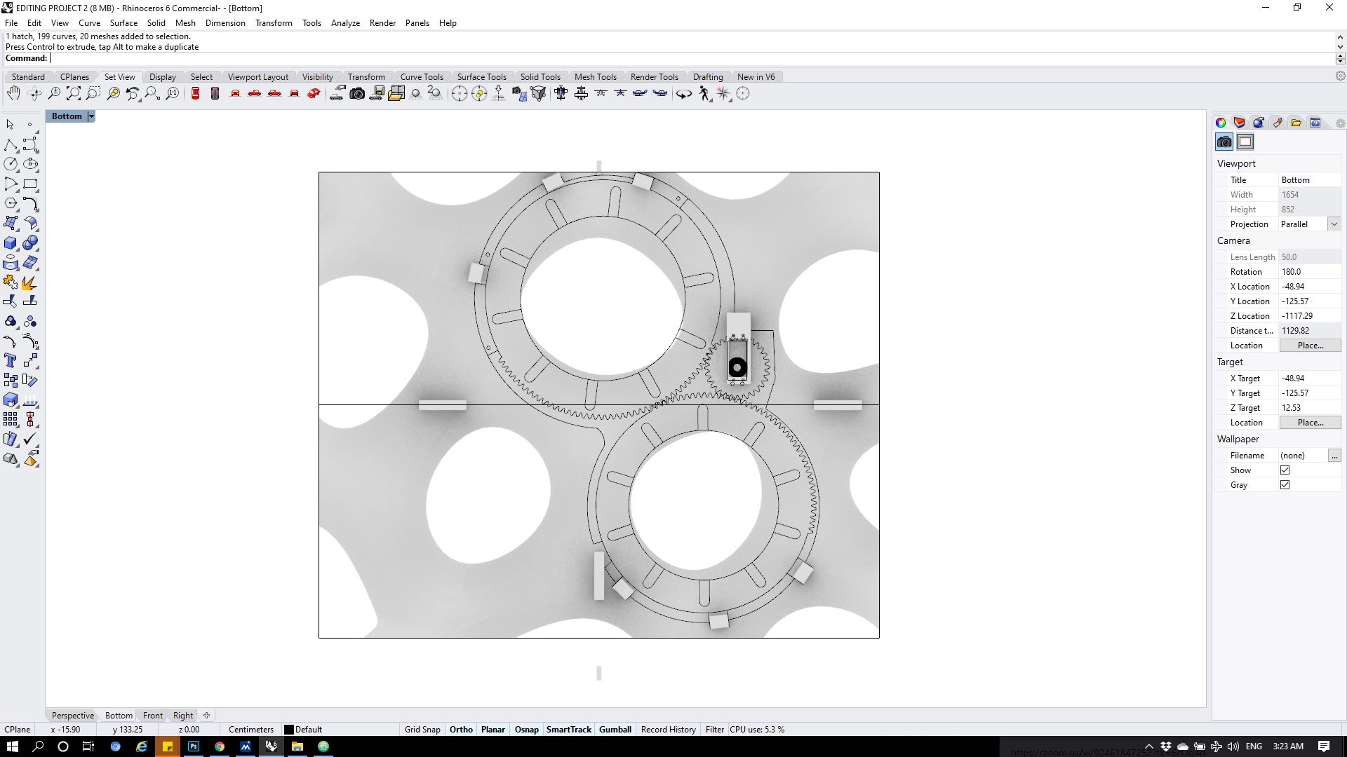
The Mechanism
-
A natural optical system that has a diaphragm and an aperture is the human eye. The iris is the diaphragm, the pupil is the aperture. … An iris diaphragm can reduce the amount light that hits a detector by decreasing the aperture, usually with “leaves” or “blades” that form a circle.
-
How does an iris mechanism work?
A number of carefully-shaped blades are anchored to two different rotating rings. As the rings rotate, the blades move, and their combined gap in overlap forms the iris. The more blades in the diaphragm, the closer is gets to maintaining a circular opening.
Design
For Design i have used Rhino , Fusion 360, Grasshopper.
First try : Failed
Sceond try :
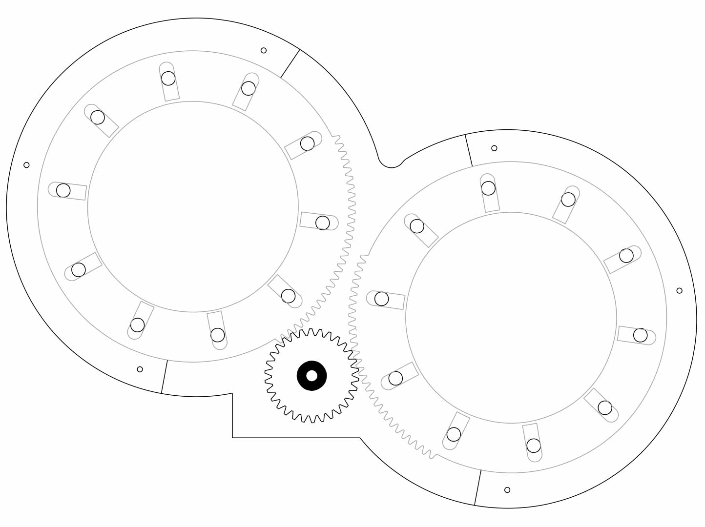
The project has 3 main components The front and back case , the Iris mechanism.
so first i have designed the Mechanism part to scale all the project on it.
The Mechanism contains 4 part :
1- Actuator.
2- Housing.
3- Blade.
4- Gear.
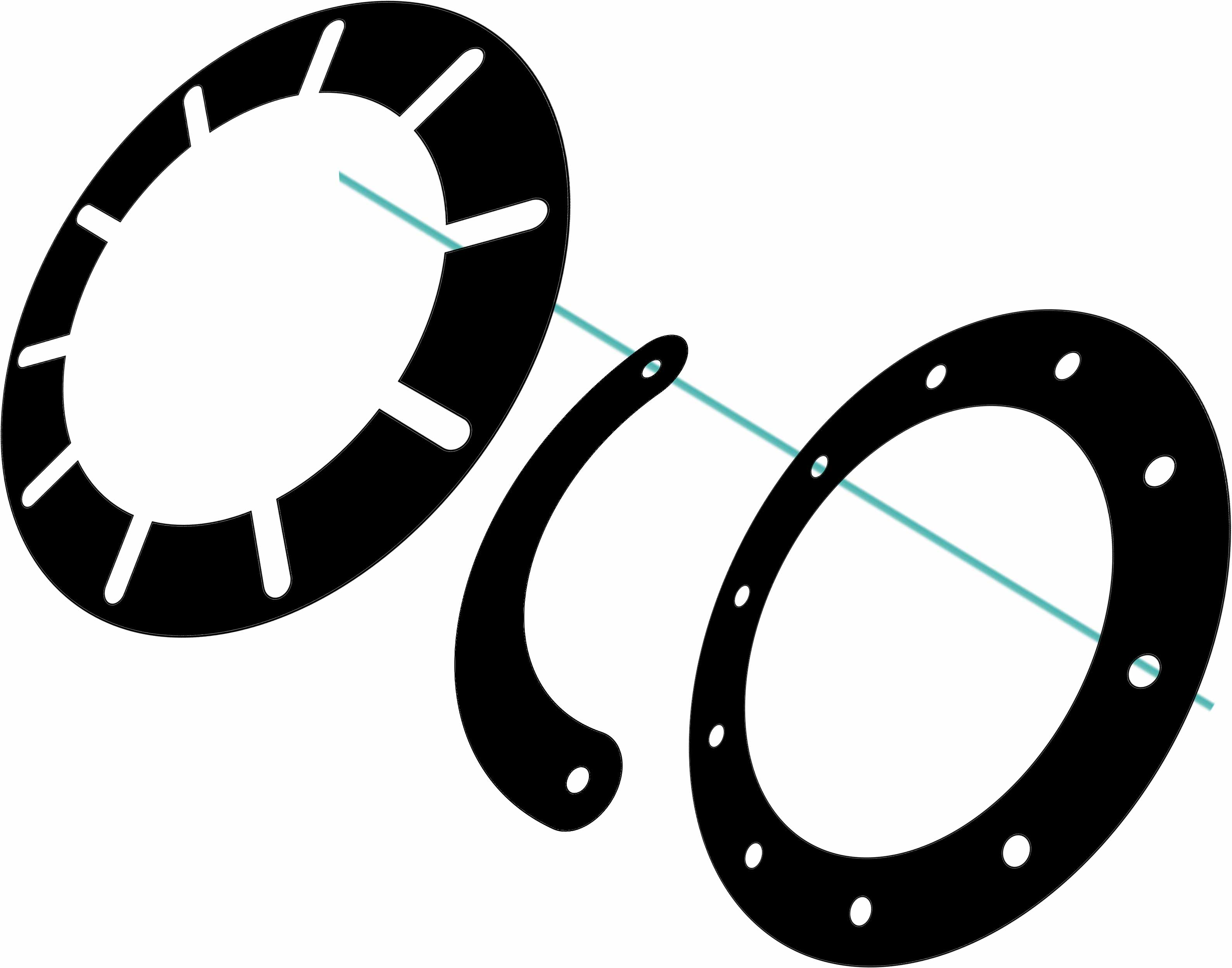
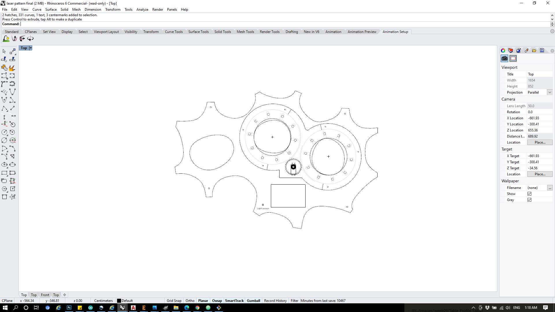
The outer Diameter for the Iris is 22.5 and the inner diameter is 16.2.
Each iris contains 10 blades
How it works: by fixing one of the blade faces on the Actuator and the other face on the housing and rotate the housing part the iris will open and close smoothly as shown below
So for the project i made 2 Iris with one Actuator base and gear in between
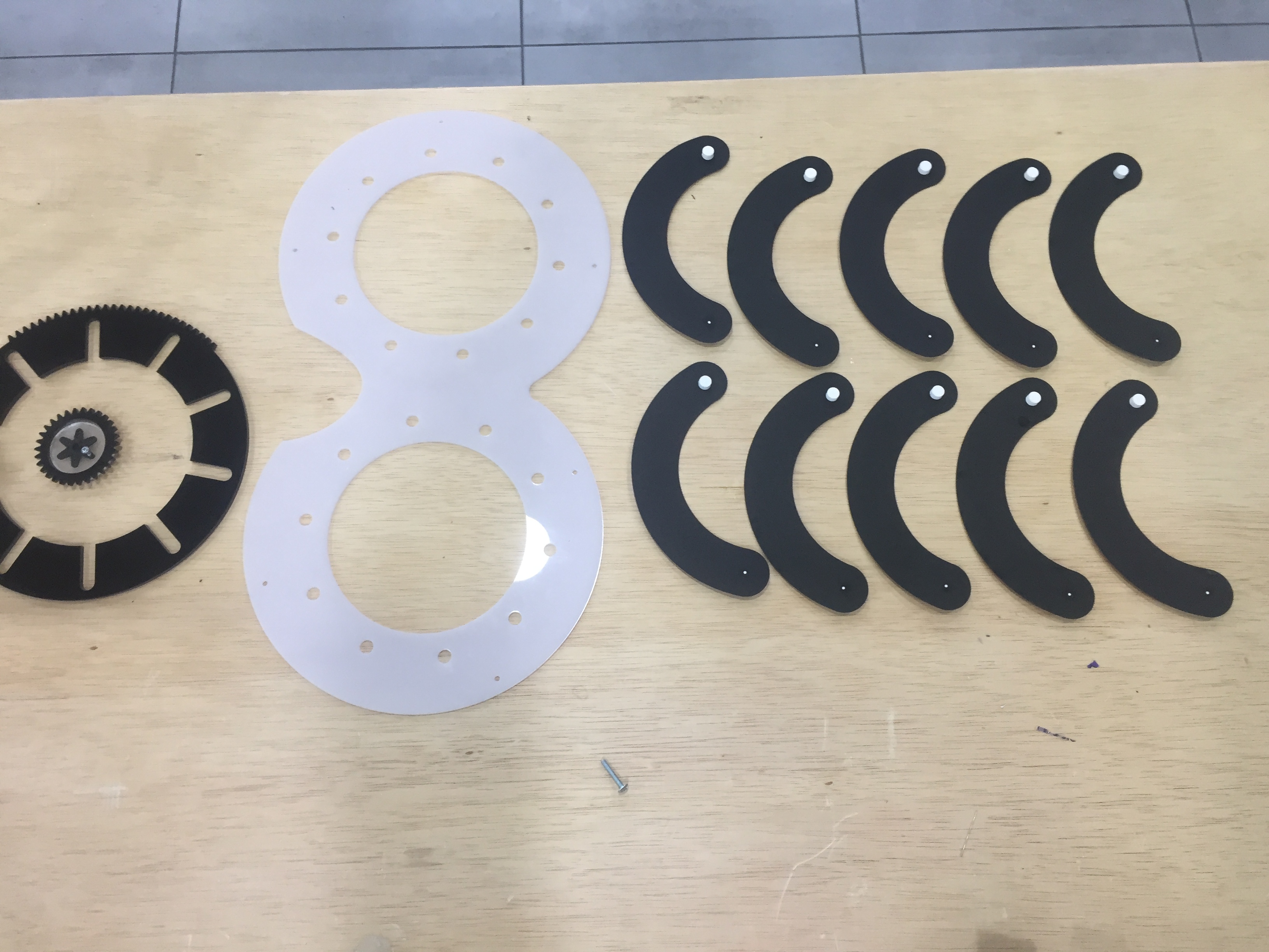
Blades:
I have cut 20 blades from the Bio-material i have made as shown below

Then i have cut the Housing and assembly all the parts.

After i assembled all the parts i connected the servo the gear and test it and it worked.
The Packging :
for the Packging i got inspired from the organic shapes and made three openings 2 of them are dynamic and one covered by bioplastic to clean the ventilated Air.
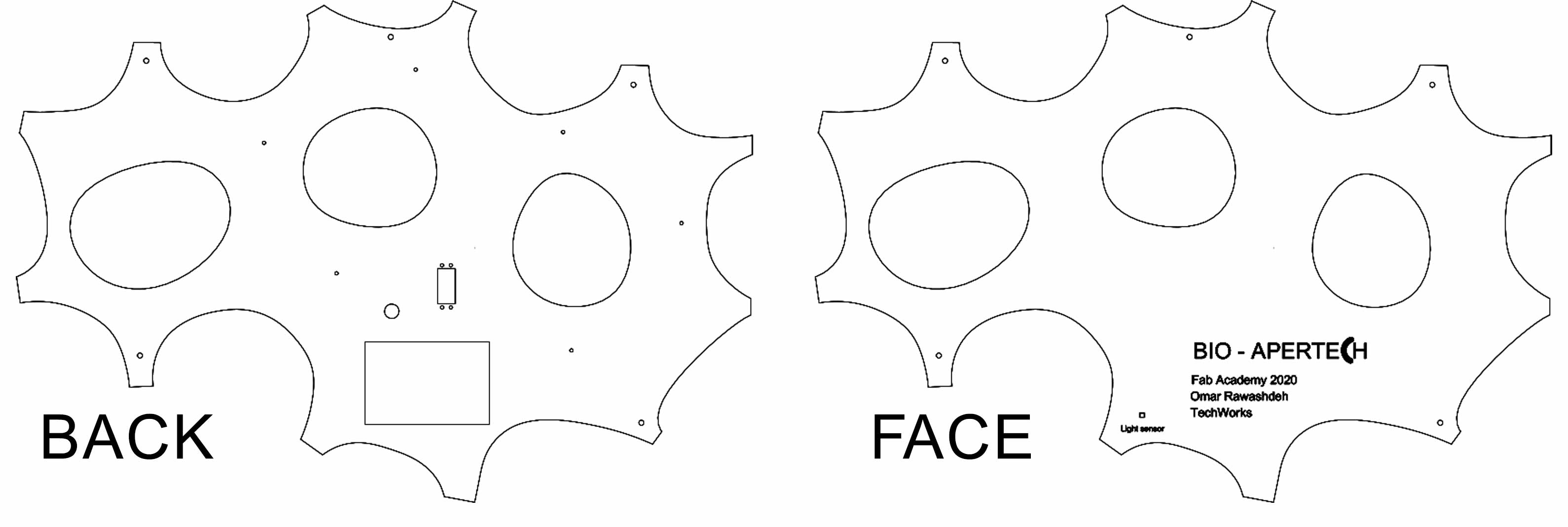
The face case include the Light sensor
The back case include 3 openings
1- the electronics box 2- Wires 3- Servo
Bio material
Download##### Files
Sourse :
First : I have to choose which bio material i want to include in my final project functions :
The function is to purify the Air from toxic dust in it, so for this function i choosed ( Activated Charcoal ) as a filter
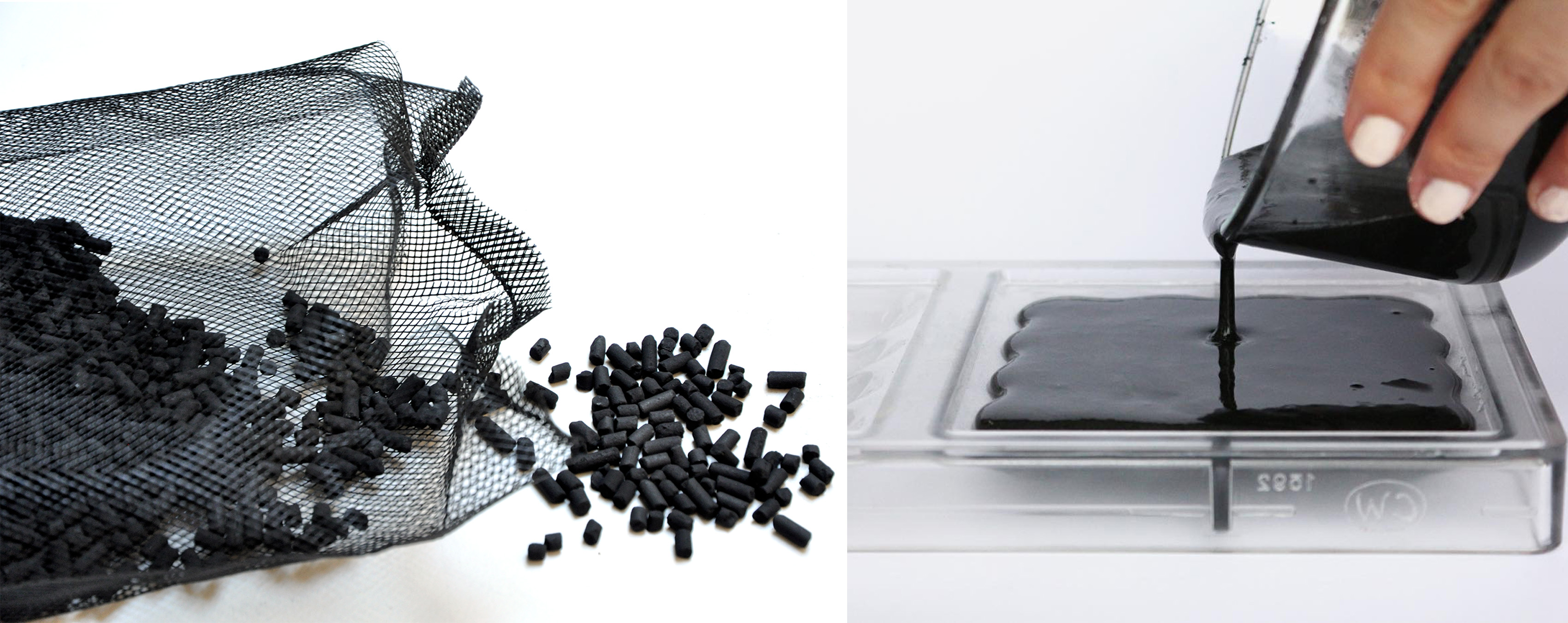
Activated charcoal is one material that seems especially applicable to Fab Lab makers, because of its ecologically sound and purifying properties. It is essentially a form of incredibly microporous carbon, processed from natural carbon-rich materials by applying various gases or chemicals to ‘burn’ in tiny holes and thus exponentially increasing its surface area. The result ? A material that can efficiently filter out all manner of impurities and toxins. A super-sponge, if you will. Bioplastics present themselves as an excellent and similarly sustainable substrate for activated charcoal with a wide range of uses.
so the bio material has multiable variables such as:
| Variable |
|---|
| Flexibility |
| Texture |
| Conductivity |
| Resistance |
I want it flexible and smooth:
So for this i have to test different recipes and quantities to get the result i want.
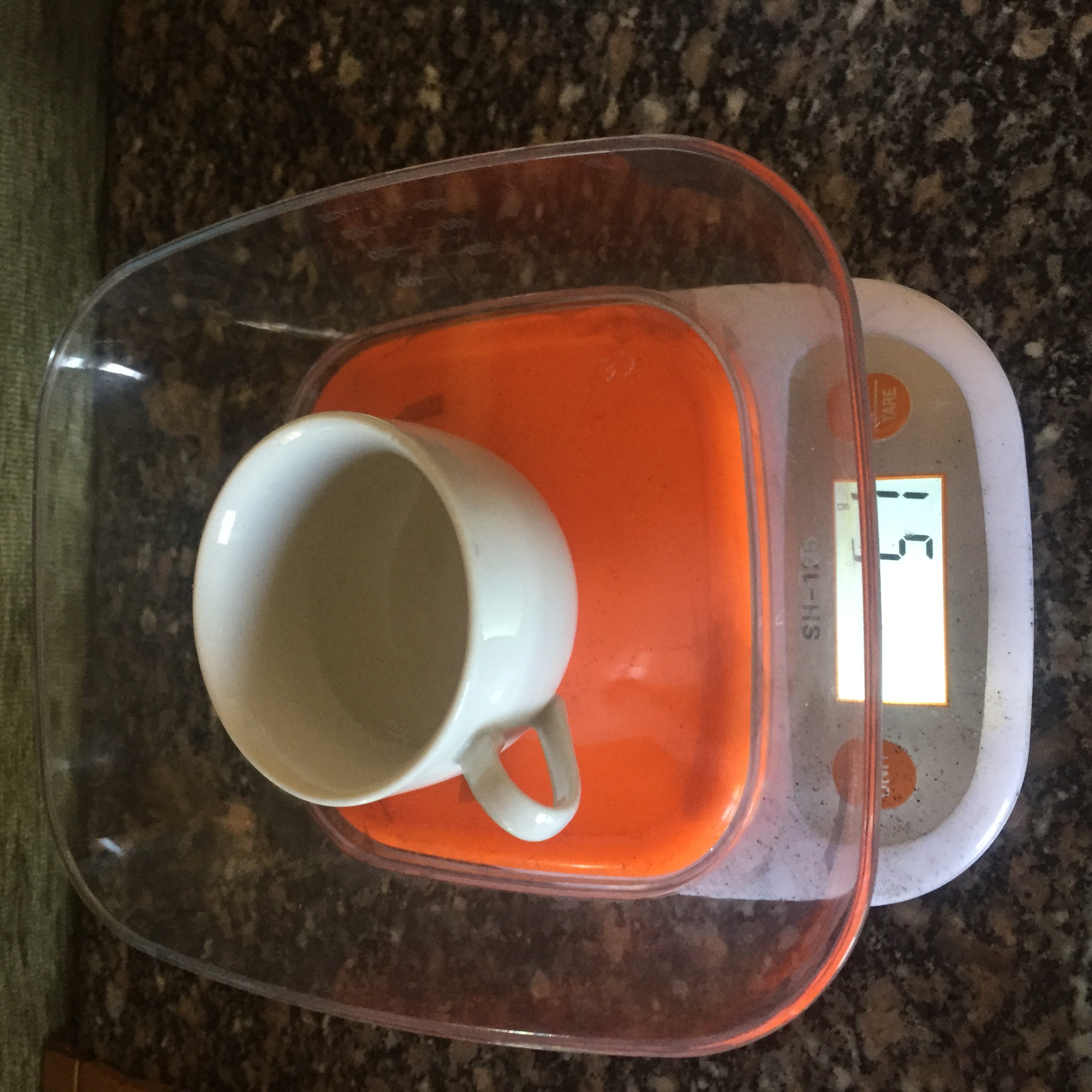
Materials
| Name | quantity |
|---|---|
| Activated Charcoal | 500g |
| Gelatine | 300 g |
| Glycerin | 300 g |
| petri dish | 10 |
| Pot | 2 |
| stove | 1 |
| scale | 1 |
| Acrylic heet | 100*60 |
First Round :
First one was not good enough and the results were too bad because of :
1 - i mixed the material without boiling the water, i just add hot water to the mixture and mix it without getting it boiled together.
2- It turned out that the bio material has differnet quantities from country to another so for the first time i have used a recipes from Mixeco and definitely it wont work in jordan because it has a totally different weather.
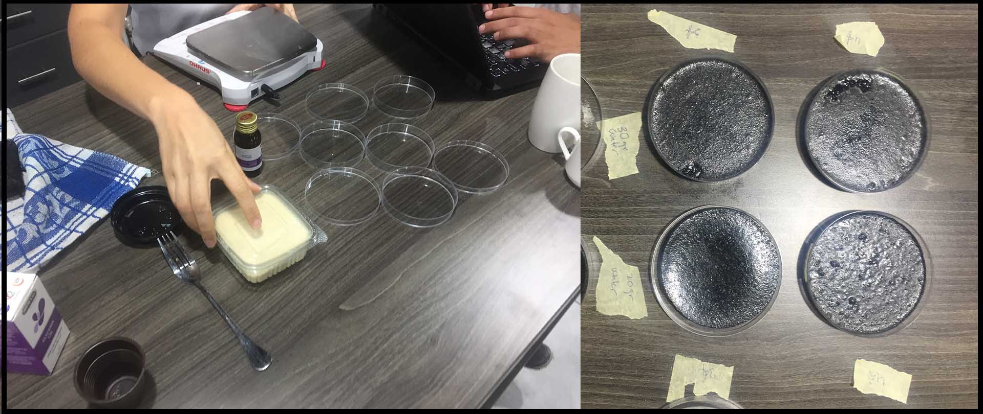
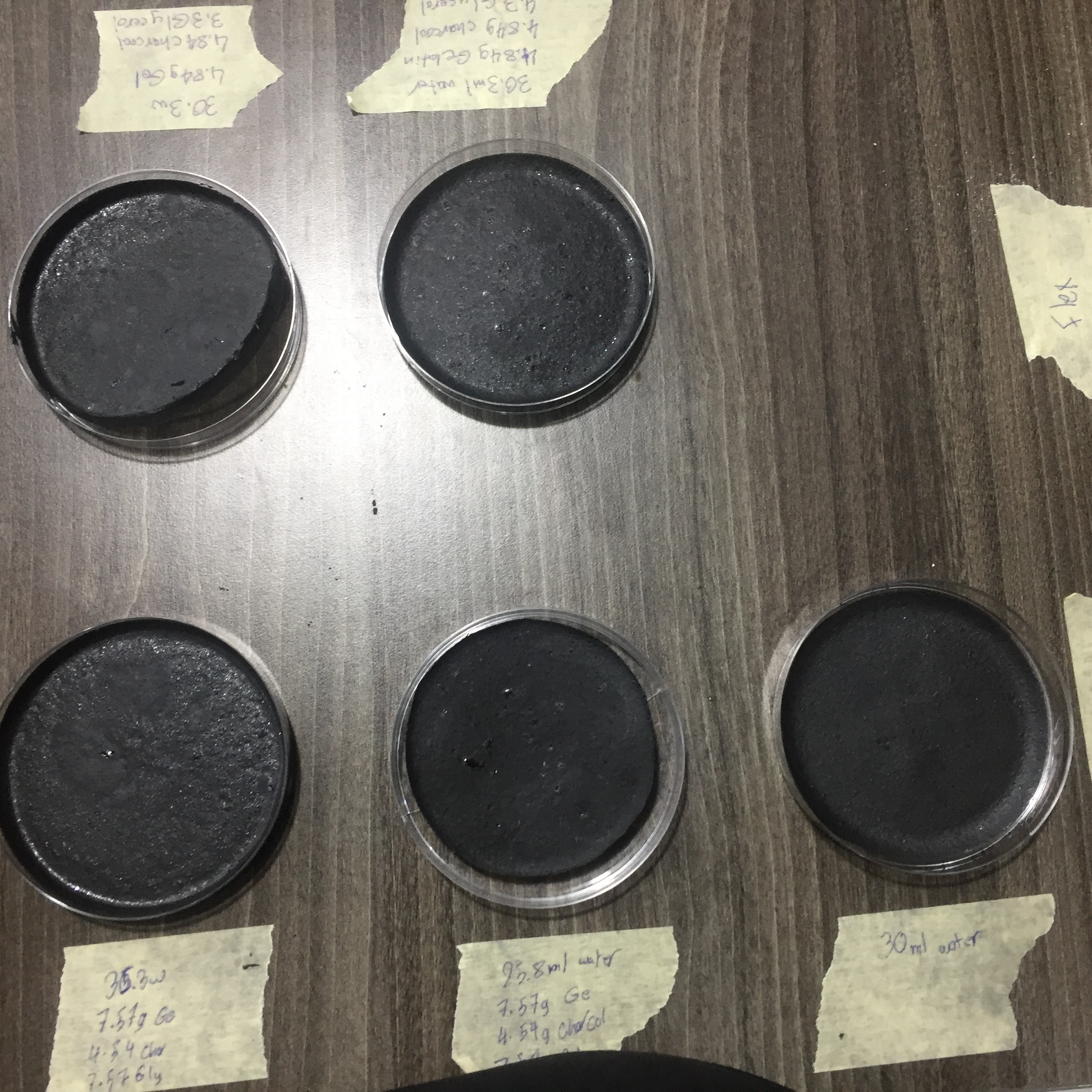
Second Round :
| Samples | Water | Gelatin | Activated Charcoal | Glycerol |
|---|---|---|---|---|
| #1 | 35 ml | 7.5 g | 4.5 g | 7.5 ml |
| #2 | 25 ml | 7.5 g | 4.5 g | 7.5 ml |
| #3 | 30 ml | 7.5 g | 4.5 g | 4.5 g |
| #4 | 30.3 ml | 4.48 g | 4.48 g | 3.30 ml |
| #5 | 30.3 ml | 4.48 g | 4.48 g | 4.3 ml |
First step :
In a cooking pot, off heat, mix the gelatin powder and the water. Stir and wait until the mixture thickens like a glue.
Step two : Start to heat the mixture on high heat. Stir time to time but not excessively to avoid additional foam. When the preparation become liquid again, add the glycerin.
Step three : Lower the heat as soon as you start to see a white deposit appearing on the surface of the mixture. Remove gently the foam with a spoon. Add the activated charcoal and stir.
Step four : Pour the preparation on a flat surface (in glass, silicone, plastic or varnished wood) with edges delimiting the desired shape. IMPORTANT : prepare your mold before starting to cook to avoid a final panic !
Step five : Wait 4/5 days of drying before removing the bioplastic material from its molding surface.
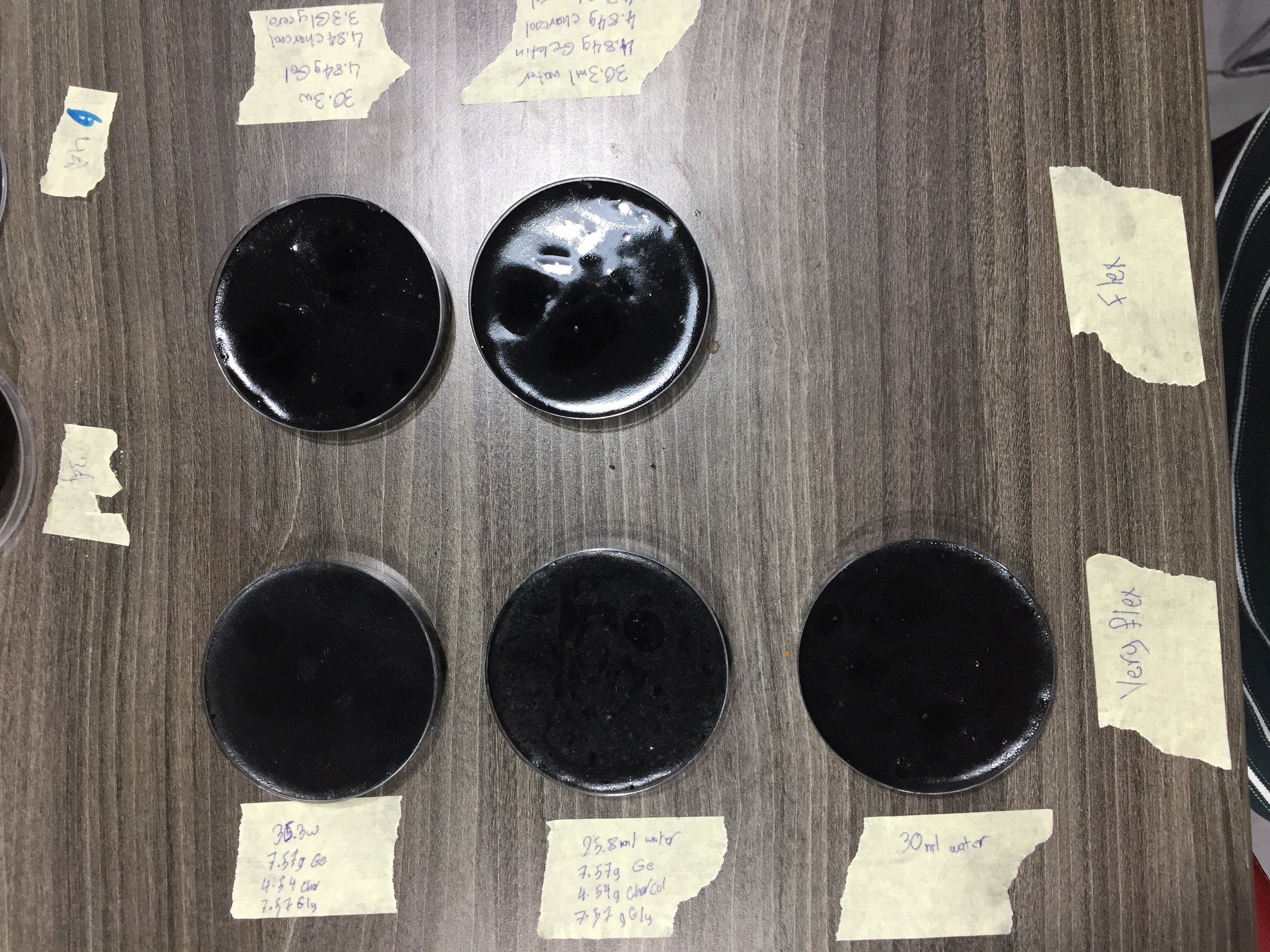
So after 4 days the samples were ready and i found that the sample # 5 was the best as shown below.
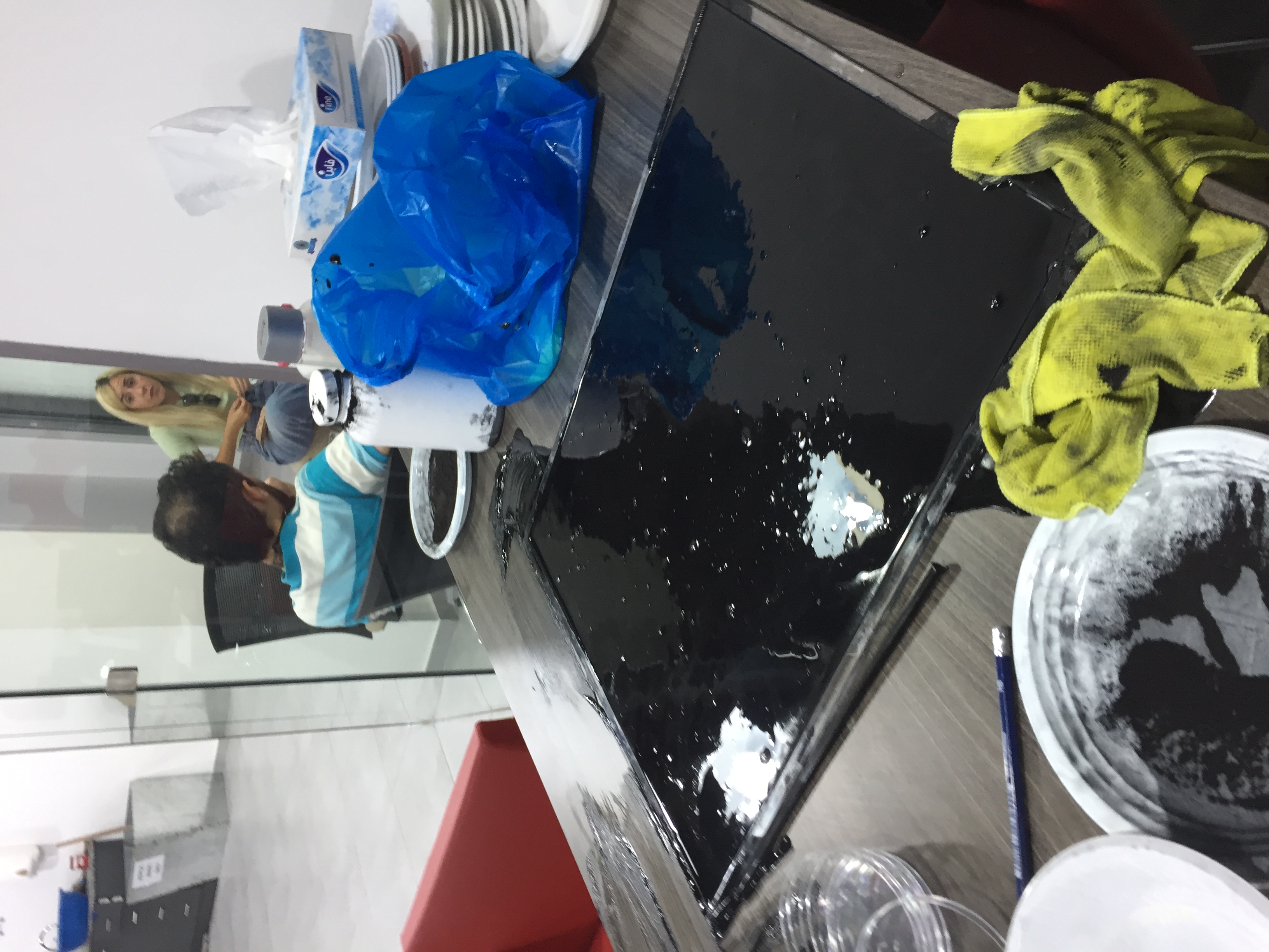
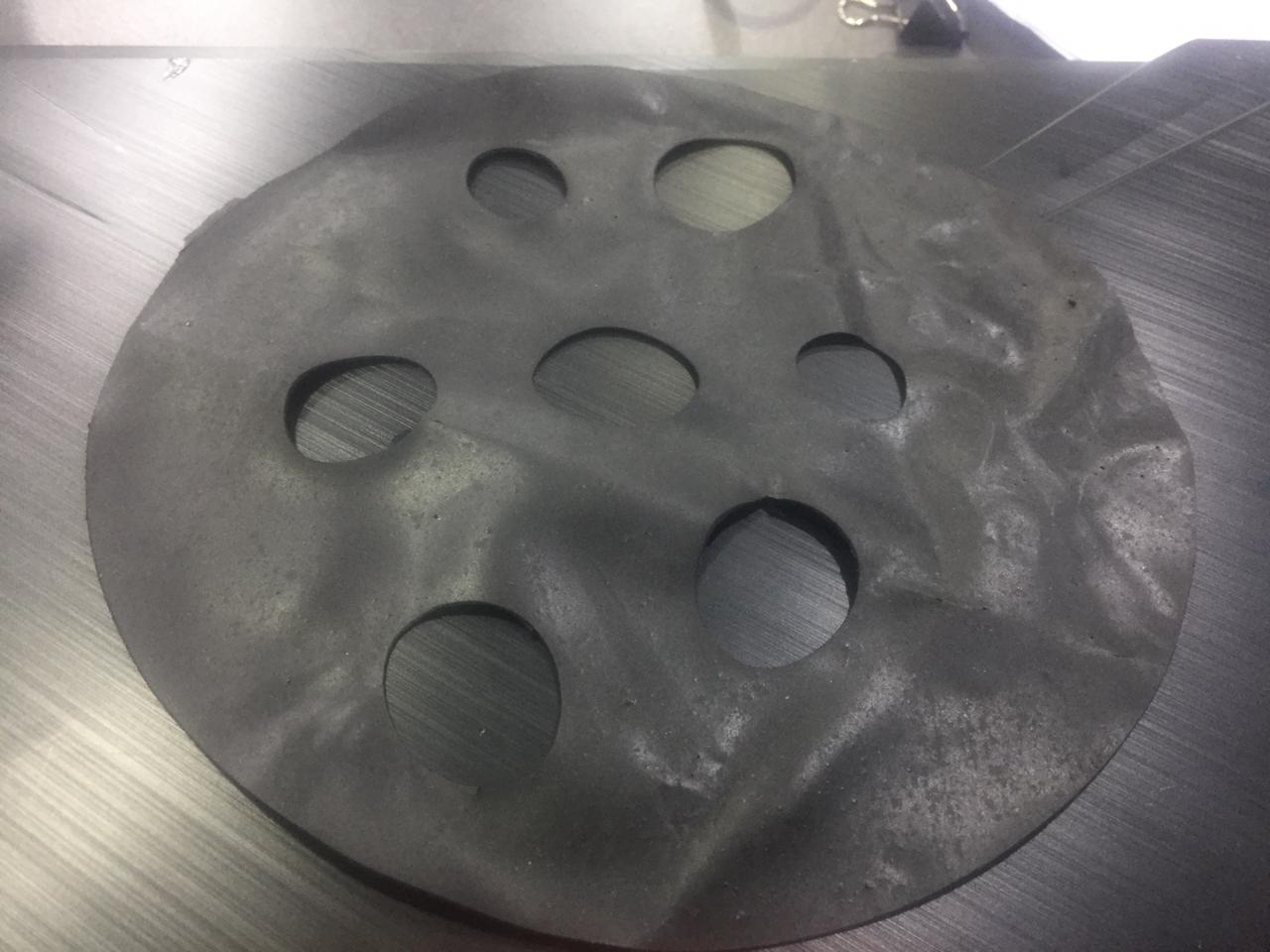
After this i wanted to make a bigger size of it in a big mold 20cm * 60cm * 3.0mm
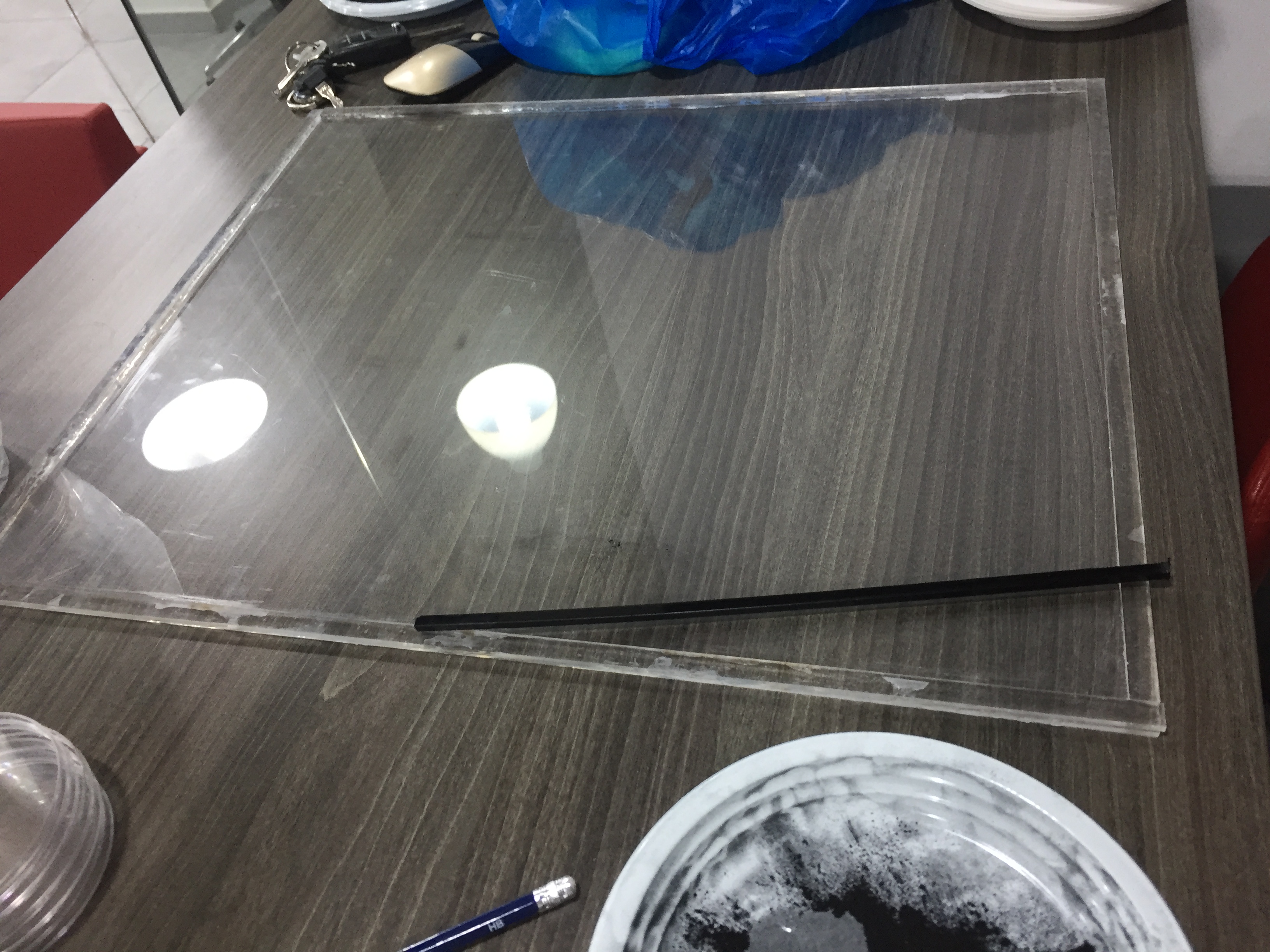
After this i tried to pour the mixture in the mold but something bad happen because the acrylic curved because of the heat of the mixture and the used surface was less than i expected:
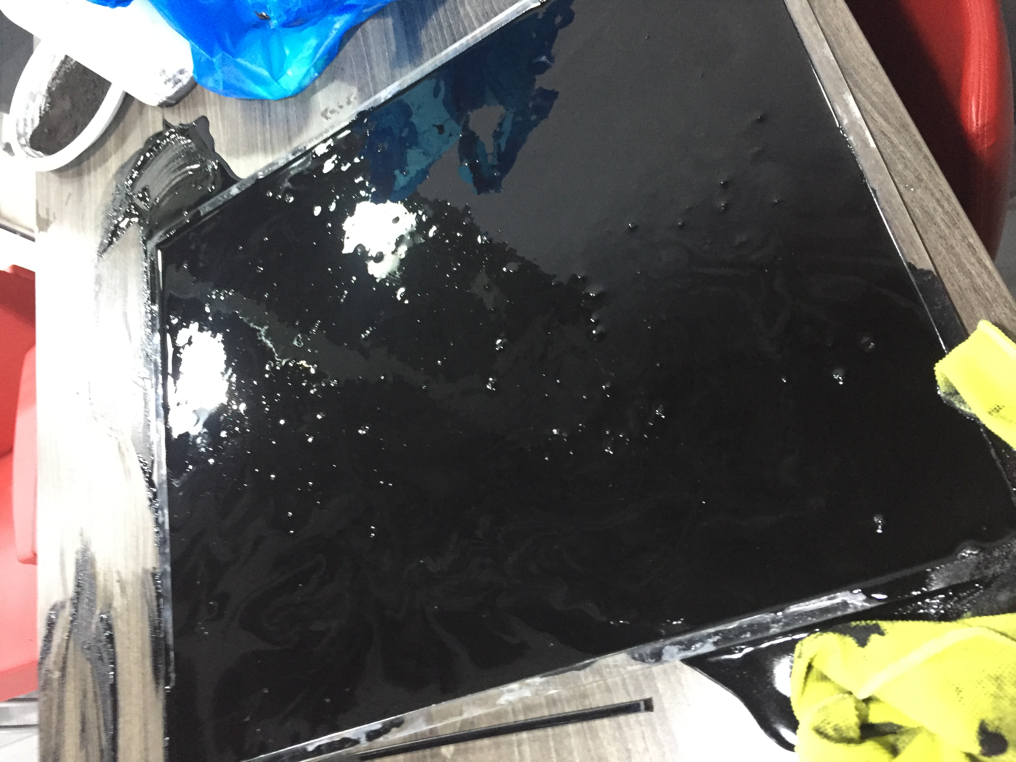
After this i wait for 4 days to get the plastic dry but guess what ! the big mold was not the same Variables of the small sample flexible and smooth as shown below :
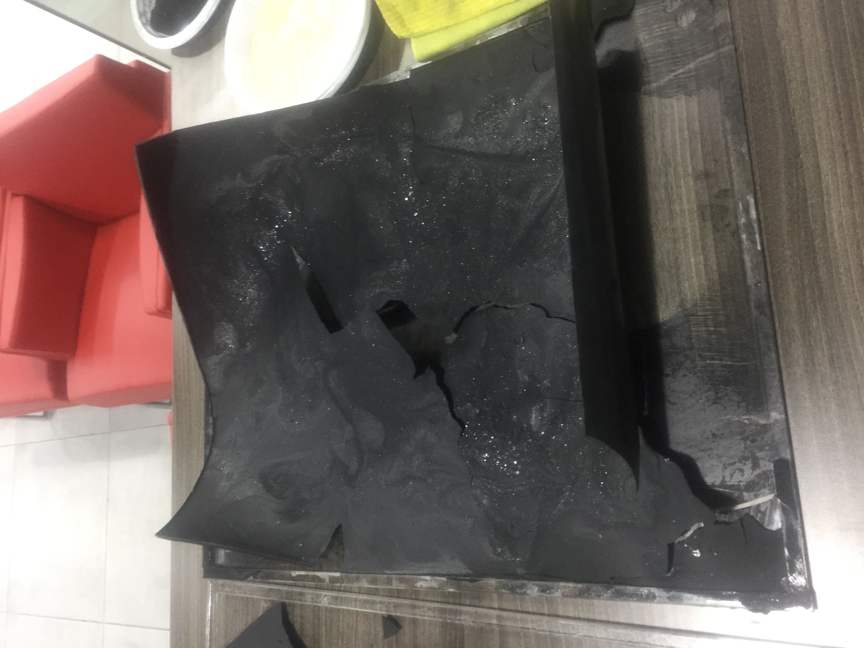
So i had to do another recipe or to add more glycerin to make it more flexible.
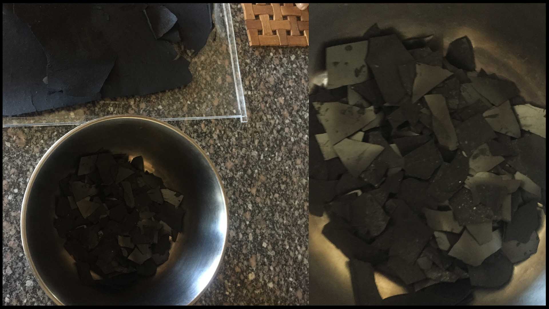
1 - i crushed the dry plastic in a pot as shown below :
2- I added 137 ml of water to the crushed plastic.
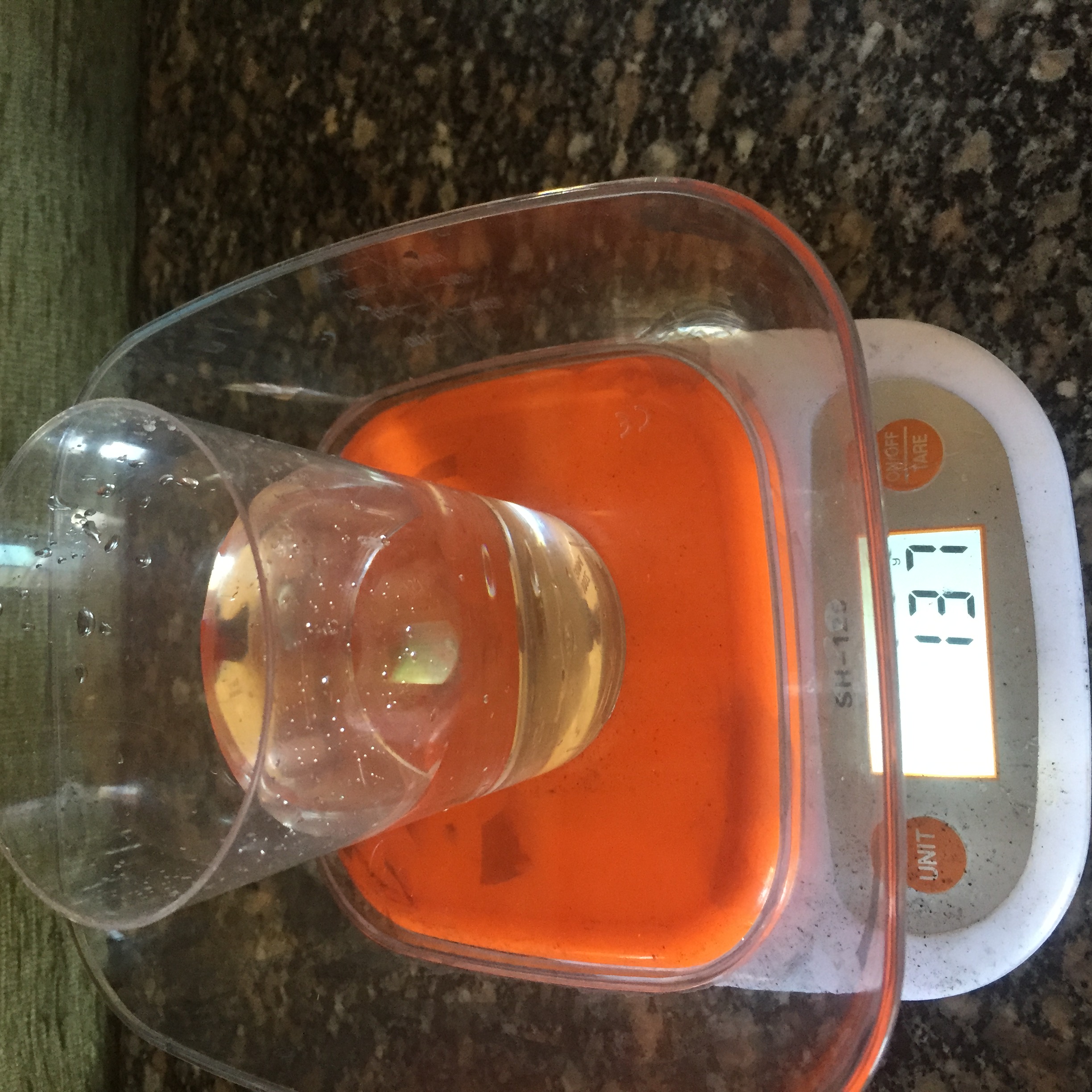
3- I added 51 ml of glycerin to the crushed plastic after boiling it.
4- i poured it again in the same mold without exposing the mixture to the Air to not get it dry during pouring it in the mold.
5- Wait for 4 days.
Hero shot
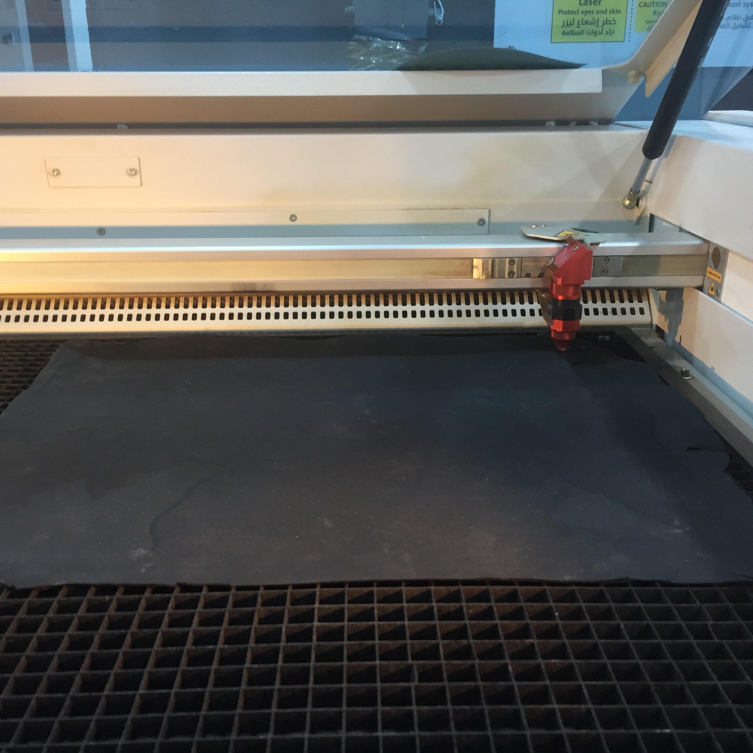
Laser Cut
Settings
    Cut:
    Power: 60%, Speed: 01%, and frequency: 5000-+
I have chosen the setting above to cut the bio-plastic into blades.
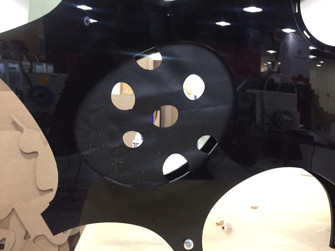
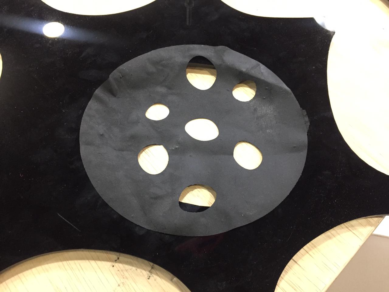
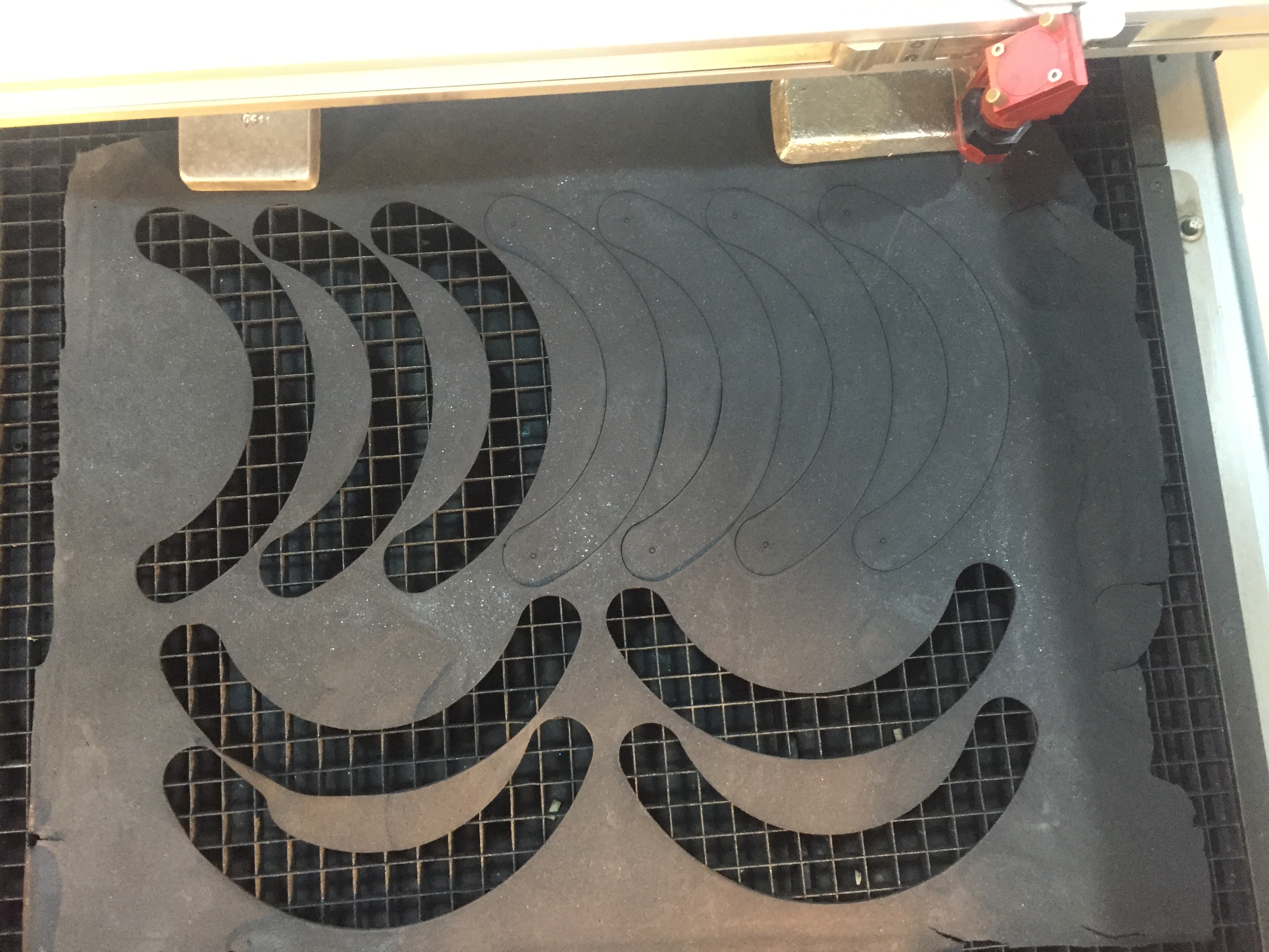
Cut the other part of bio-material and assembly it :
File : Pattern
Cut the piece :
Settings :
Power: 30%, Speed: 0.80%, and frequency: 3000-+
Assembly :
HERO SHOT
Electronics
Input :
Files :
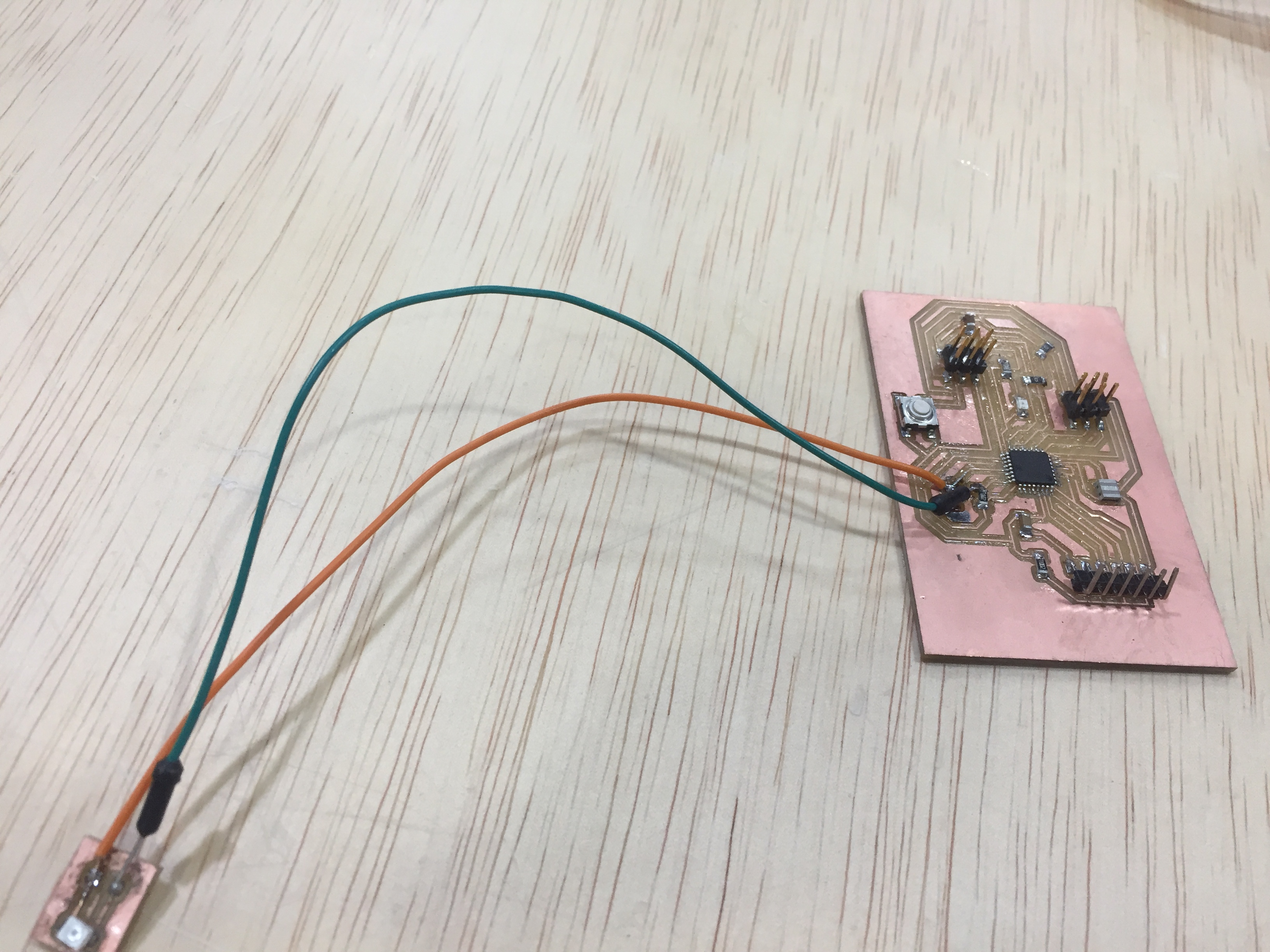
For this week i want to work on the final board (Phototransistor + Servo):
## Input Phototransistor with Servo : The phototransistor works just like a normal transistor, where the base current is multiplied to give the collector current, except that in a phototransistor, the base current is controlled by the amount of visible or infrared light where the device only needs 2 pins.
microcontroller :
Atmega 328 :
Pinout :
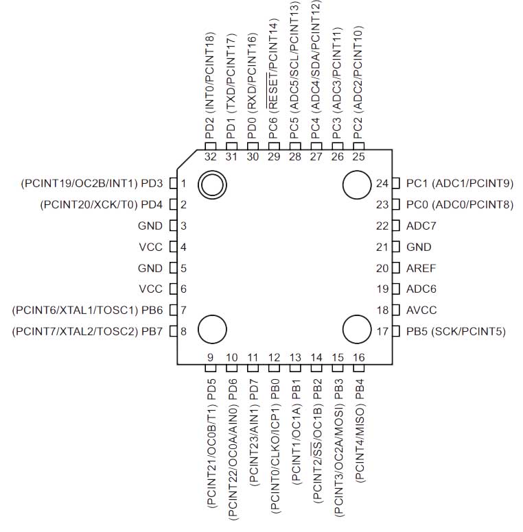
Pin Descriptions :
| VCC | Digital supply voltage. |
| GND | Ground |
| Port B (PB7:0) | Port B is an 8-bit bi-directional I/O port with internal pull-up resistors (selected for each bit). The Port B output buffers havesymmetrical drive characteristics with both high sink and source capability. As inputs, port B pins that are externally pulledlow will source current if the pull-up resi |
| Port C (PC5:0) | Port C is a 7-bit bi-directional I/O port with internal pull-up resistors (selected for each bit). The PC5..0 output buffers havesymmetrical drive characteristics with both high sink and source capability. As inputs, Port C pins that are externally pulledlow will source current if the pull-up resistors are activated. The port C pins are tri-stated when a reset condition becomes active, even if the clock is not running. |
Input sensor :
Files :

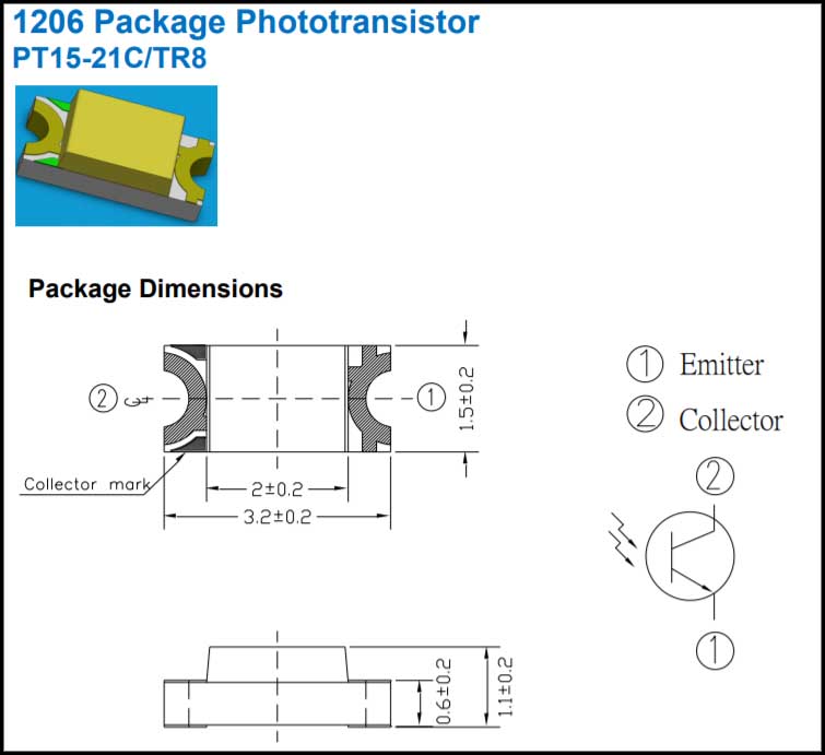
1206 Package Phototransistor:
It has to pin one is the Collector and the other is the Emitter
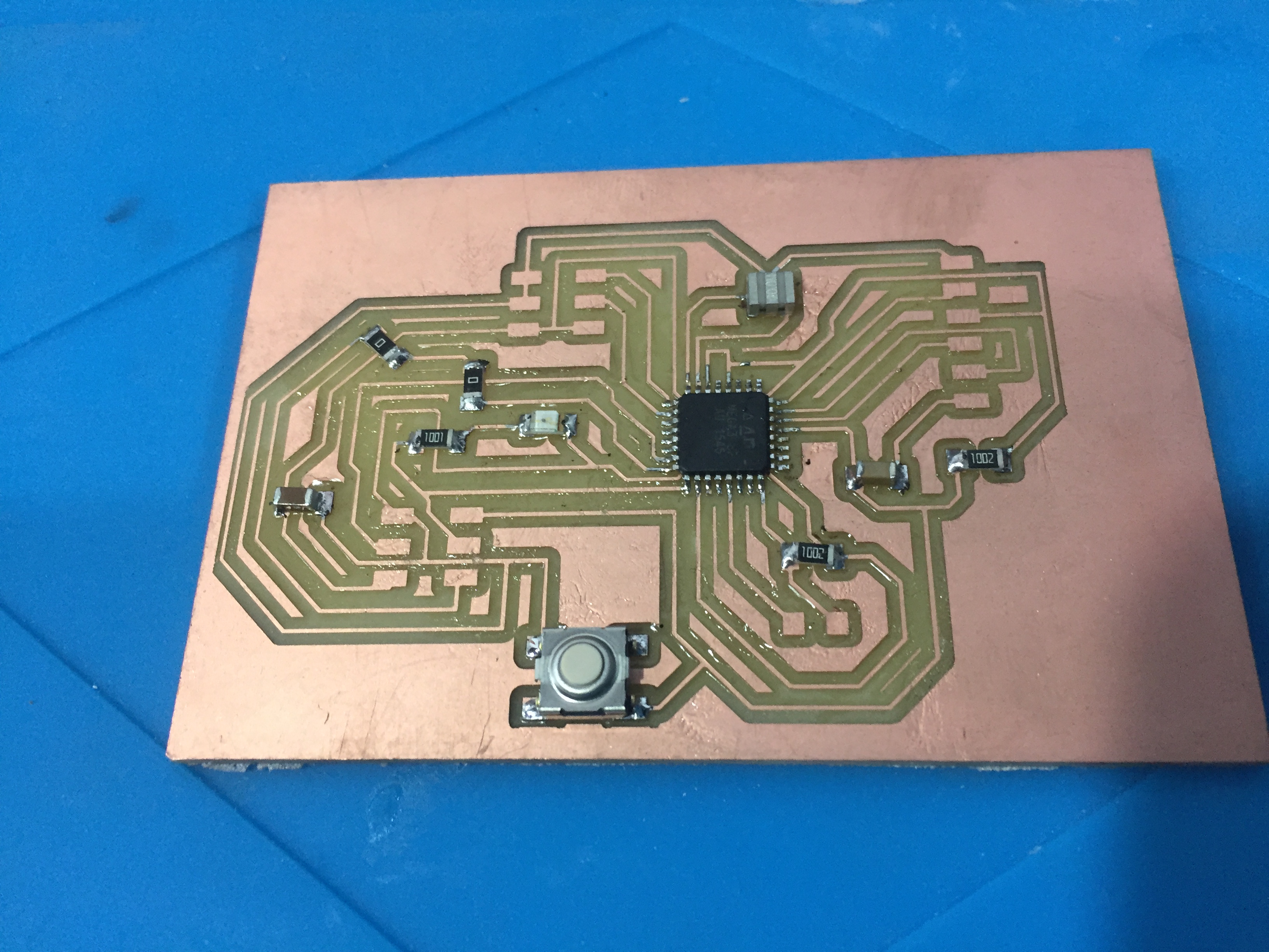
Working with Board Design :
As given in the Niel’s Board for the Input week as shown below im going to use same routing and add some components that fit my final project Board.
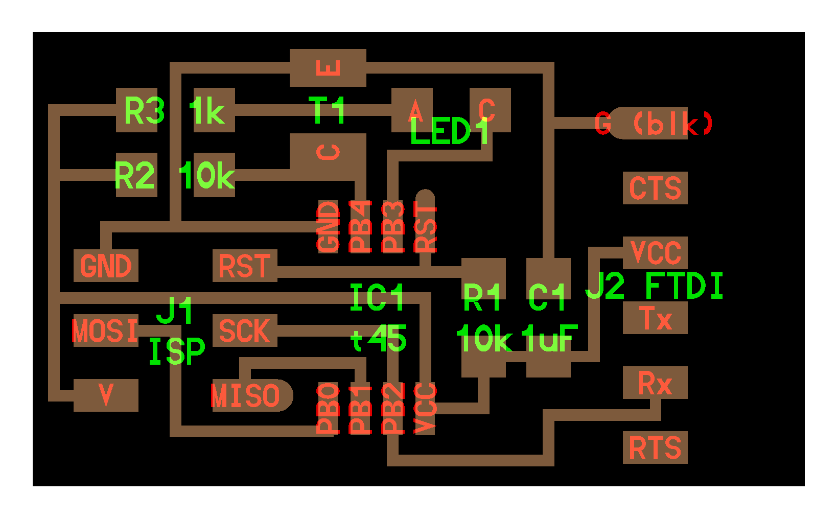
### The Schematic
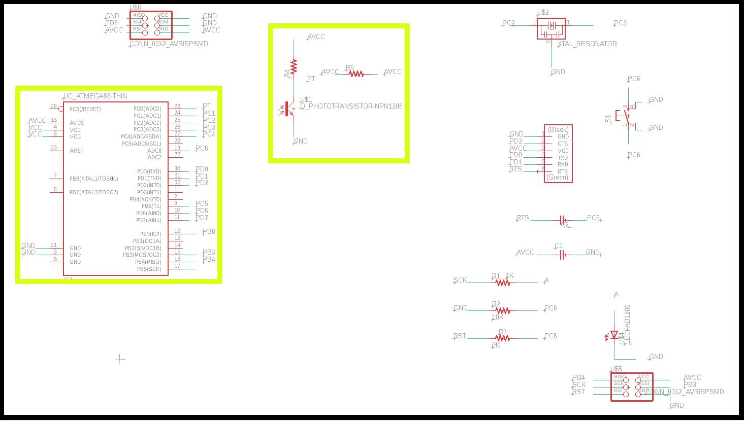
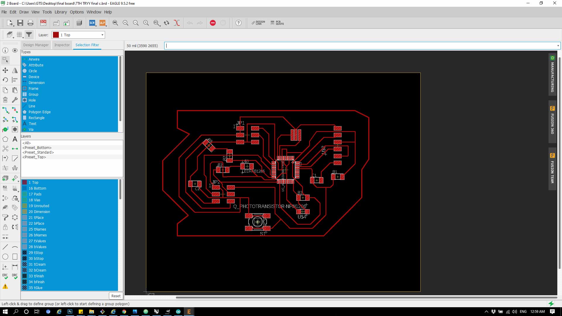
### The Board Design
Check how export the schematic to design the board in Week7
| Component | Quantity | |
|---|---|---|
| 1 | ATmega328p | 1 |
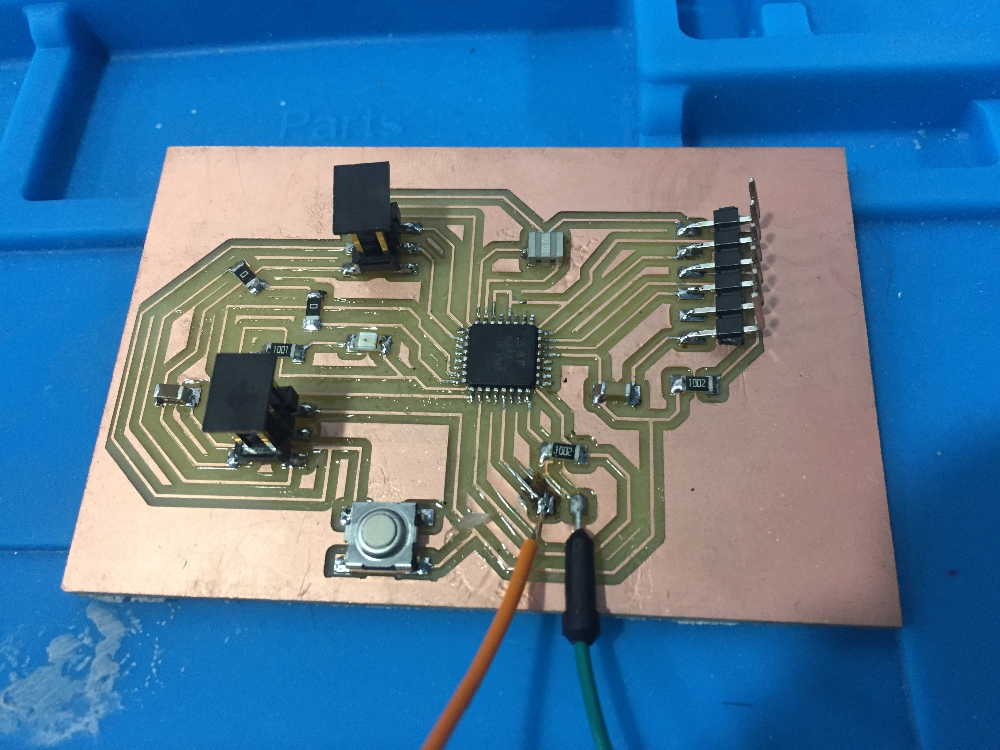
| 2 | PIn header | 2 |
| 3 | XTAL | 1 |
| 4 | 10K resistor | 3 |
| 5 | 1K Resistor | 1 |
| 6 | LED | 1 |
| 7 | FTDI | 1 |
| 8 | 0.1 C | 1 |
| 1 C | 1 |
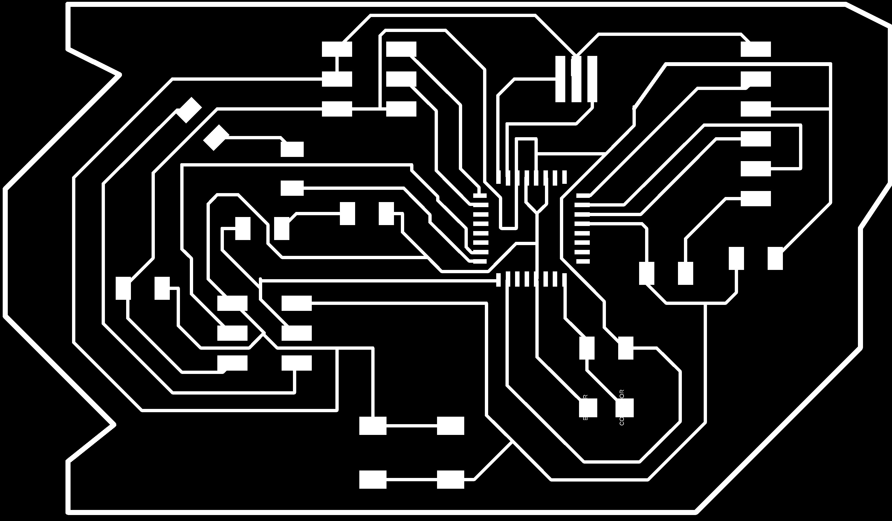
How to Export the Board to Image :
1- From File >> Export >> Image
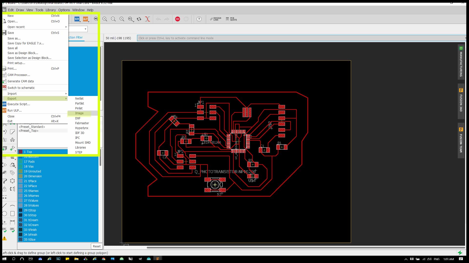
2- From the menu change the Monochrome and tick it and change the resolution to 1000 instead of 150.
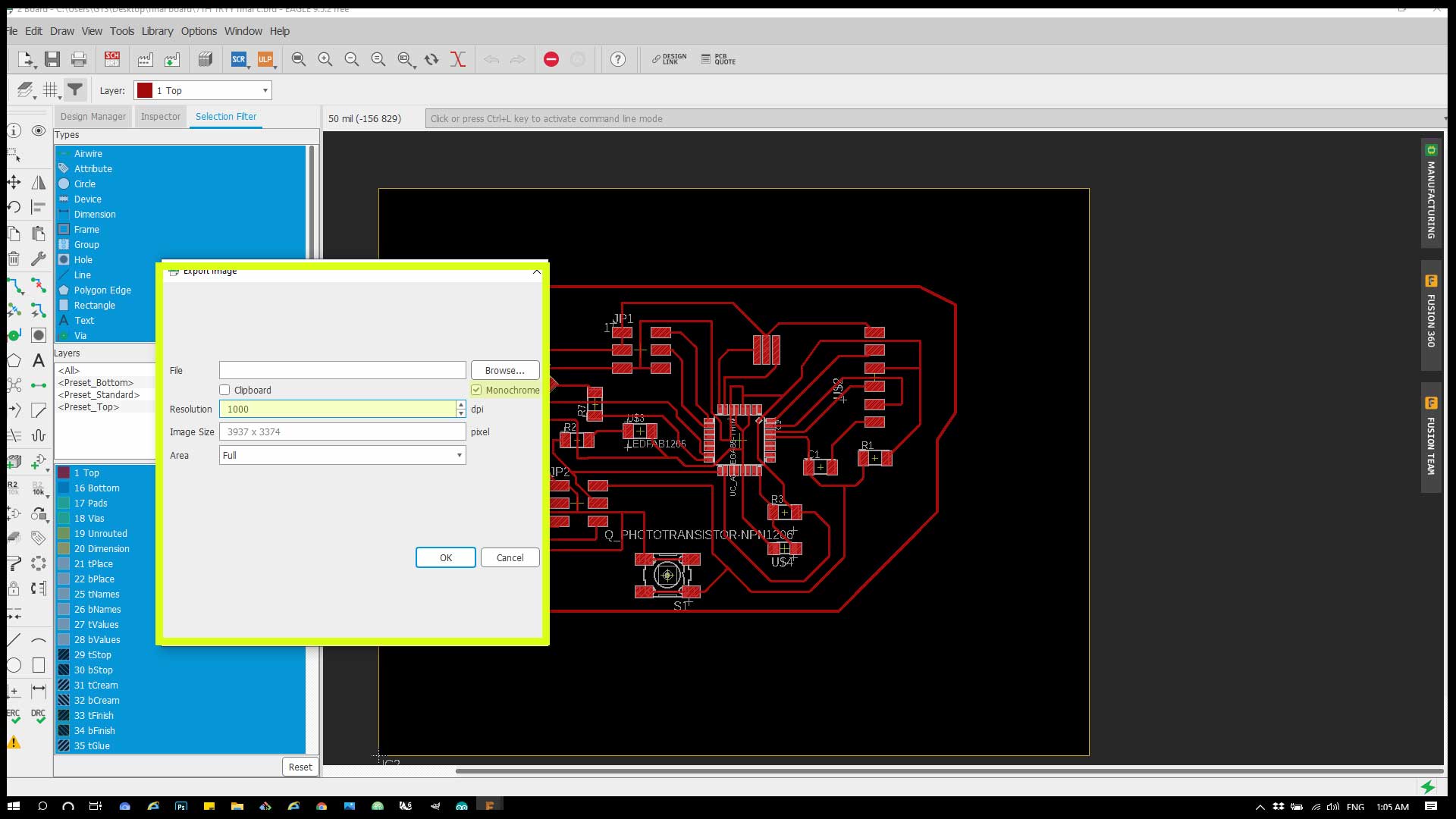
Final Png :
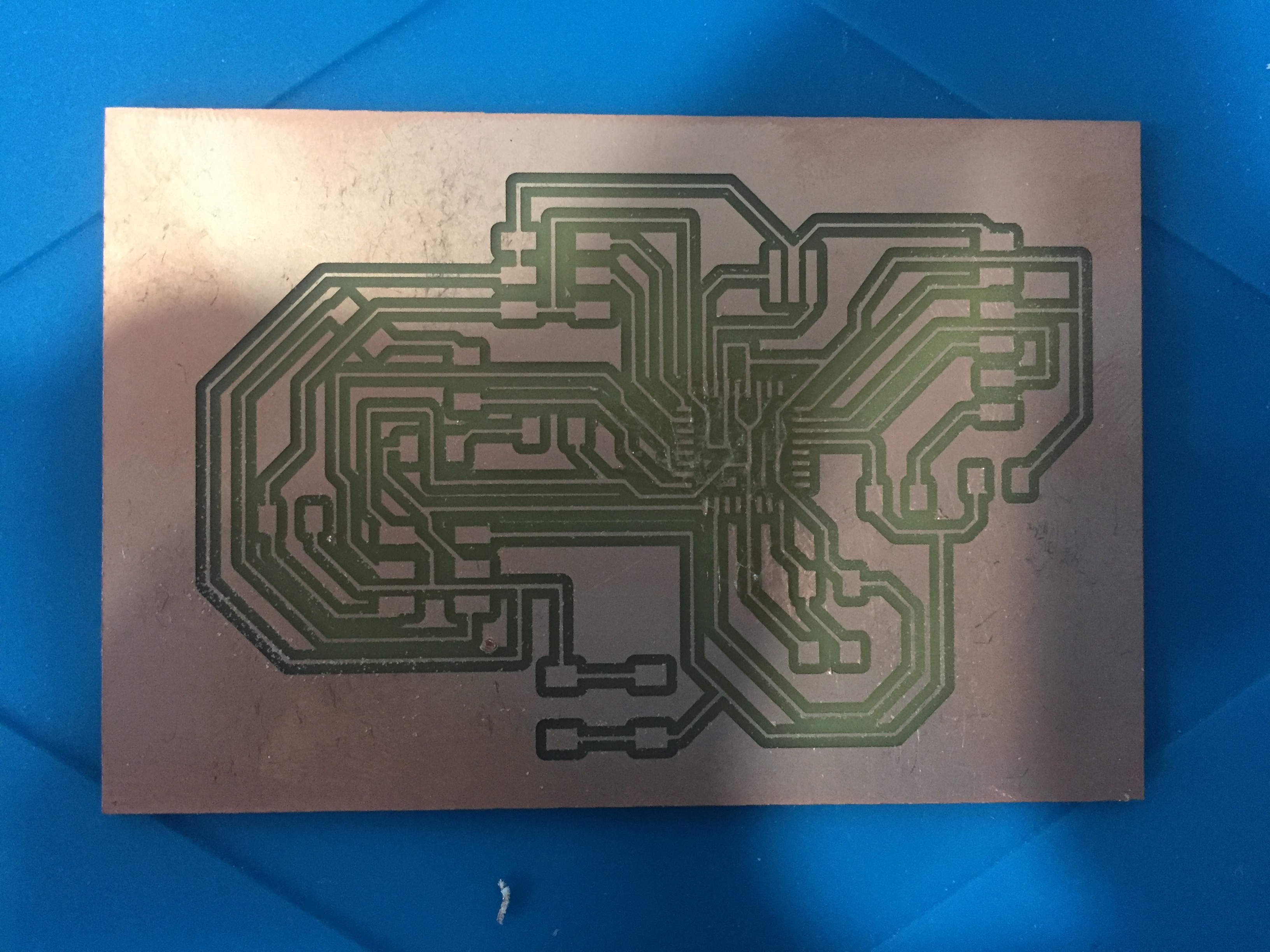
Check how to work with RML and mods in Week7
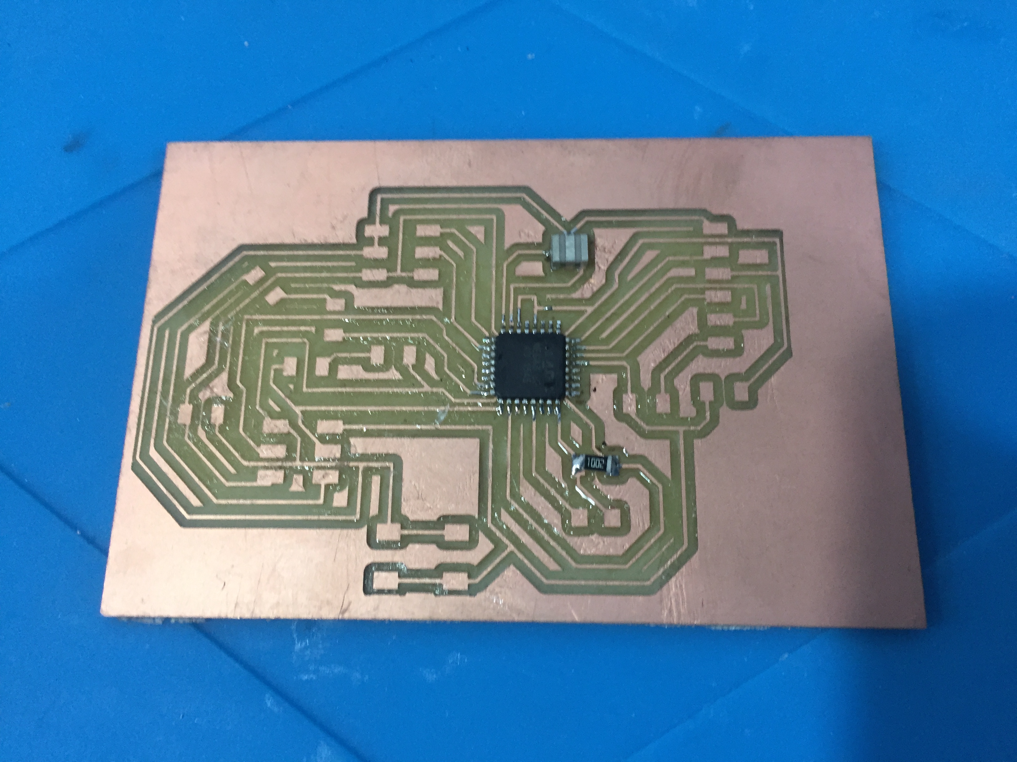
Soldering :
## Code :
                 #include <Servo.h>     // Library for Servo Motor

           int potpin=A0;// initialize analog pin 0, connected with photovaristor

           int ledpin=13;// initialize digital pin 13, output regulating the brightness of LED

           int val=0;// initialize variable val

           Servo myServo;   // define servo name


           /* The setup() function is called when a sketch starts. It is used to initialize variables, pin modes, start using libraries, etc. This function will only run once, after each power up or reset of the Arduino board. */


           void setup()

           {

           pinMode(ledpin,OUTPUT);// set digital pin 13 as “output”

           Serial.begin(9600);   // set baud rate at “9600”

           myServo.attach(5);   // servo pin

           myServo.write(0);     // servo start position

           }


           /* The loop() function executes the program repeatedly until Specified. */


           void loop()

           {

           val=analogRead(potpin);// read the analog value of the sensor and assign it to val

           Serial.println(val);// display the value of val

           analogWrite(ledpin,val);// turn on the LED and set up brightness(maximum output value 255)

           delay(10);// wait for 0.01

           if(val>200)

           {

           myServo.write(90);

           }

           else

           {

           myServo.write(0);

           }

           }
The code controls the light intensity from 0 - 1023 and rotate the Servo from 0 - 180 degree.
# Hero shot
3d print
File :
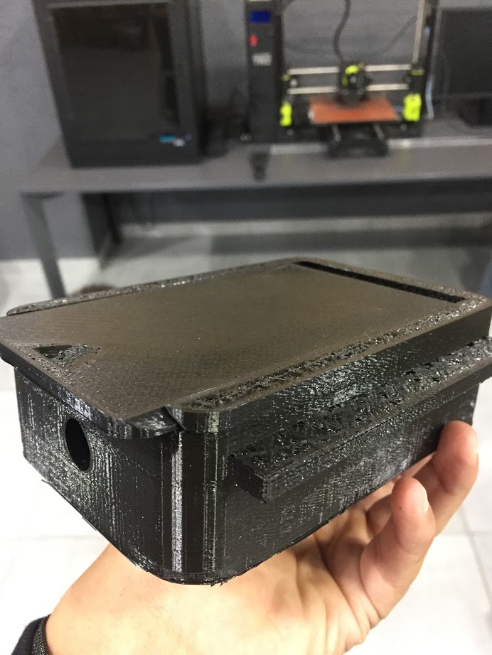
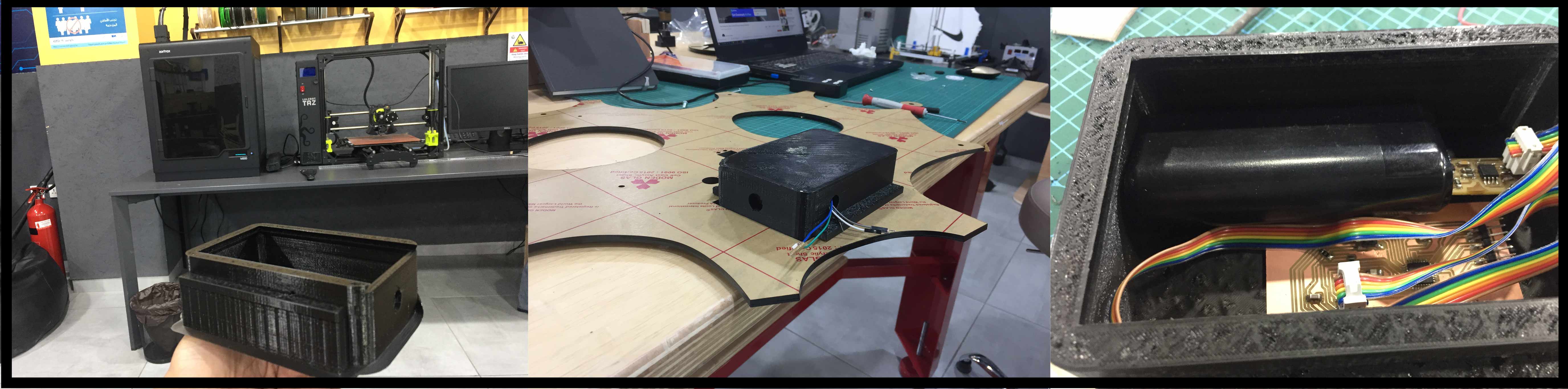
Electronics box :
I have designed a box with slide opening to but the power supply and the board inside it.
The box dimensions 140.00116.746.68.
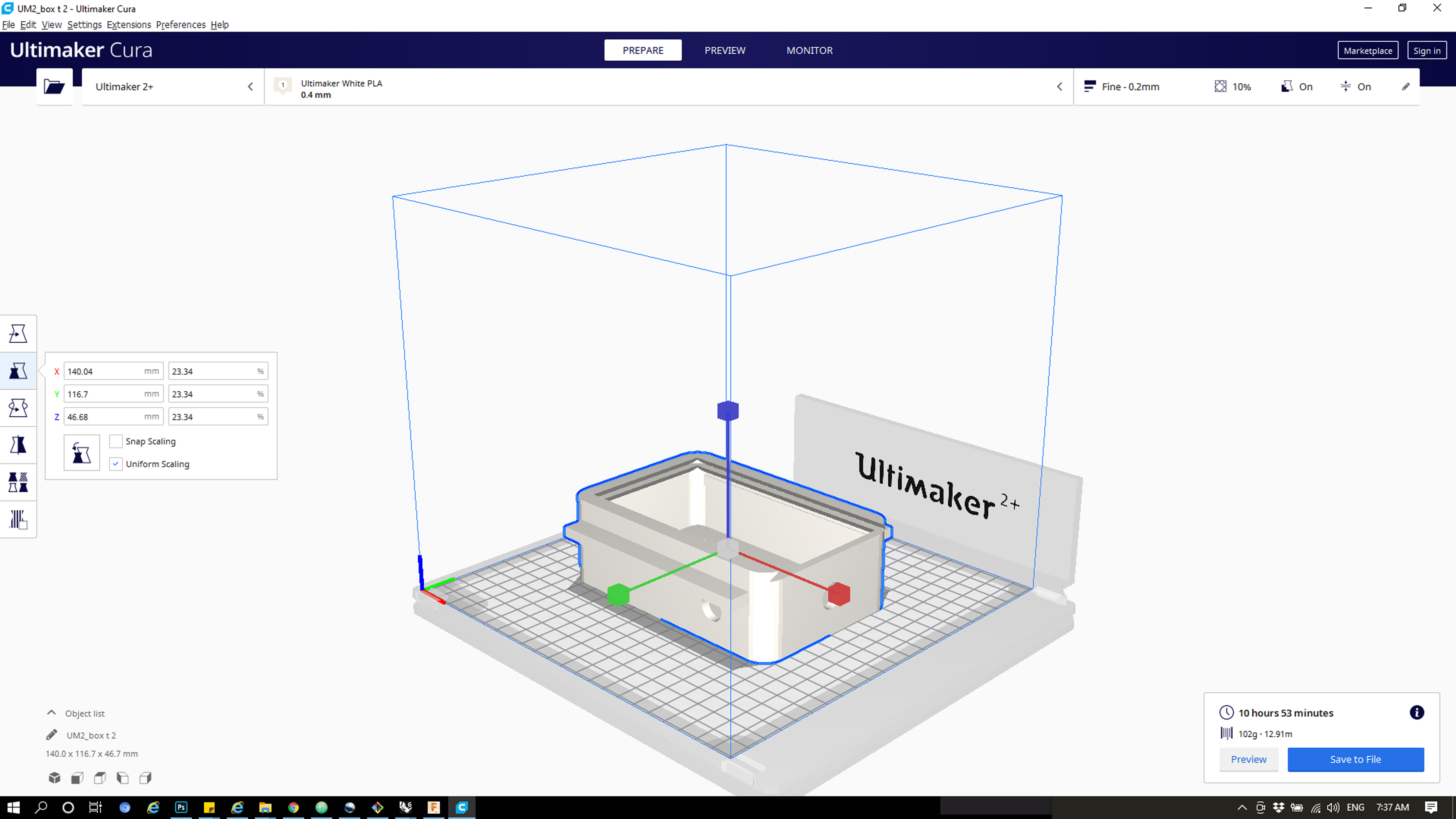
Model :
Printing :
Hero shot :
Applications :
Sun :
I have read the sun intensity during 2 hours (1pm and 2pm) and i found out that the reads is around 390-405
  #include <Servo.h>     // Library for Servo Motor

            int potpin=A0;// initialize analog pin 0, connected with photovaristor

            int ledpin=13;// initialize digital pin 13, output regulating the brightness of LED

            int val=0;// initialize variable val

            Servo myServo;   // define servo name


            /* The setup() function is called when a sketch starts. It is used to initialize variables, pin modes, start using libraries, etc. This function will only run once, after each power up or reset of the Arduino board. */


            void setup()

            {

            pinMode(ledpin,OUTPUT);// set digital pin 13 as “output”

            Serial.begin(9600);   // set baud rate at “9600”

            myServo.attach(5);   // servo pin

            myServo.write(0);     // servo start position

            }


            /* The loop() function executes the program repeatedly until Specified. */


            void loop()

            {

            val=analogRead(potpin);// read the analog value of the sensor and assign it to val

            Serial.println(val);// display the value of val

            analogWrite(ledpin,val);// turn on the LED and set up brightness(maximum output value 255)

            delay(10);// wait for 0.01

            if(val>490)

            {

            myServo.write(140);

            }

            else

            {

            myServo.write(0);

            }

            }
Room and phone Light Test :
I have read the analog while the room light was open and then closed the light then i read the analog while phone light was open and close
      #include <Servo.h>     // Library for Servo Motor

                int potpin=A0;// initialize analog pin 0, connected with photovaristor

                int ledpin=13;// initialize digital pin 13, output regulating the brightness of LED

                int val=0;// initialize variable val

                Servo myServo;   // define servo name


                /* The setup() function is called when a sketch starts. It is used to initialize variables, pin modes, start using libraries, etc. This function will only run once, after each power up or reset of the Arduino board. */


                void setup()

                {

                pinMode(ledpin,OUTPUT);// set digital pin 13 as “output”

                Serial.begin(9600);   // set baud rate at “9600”

                myServo.attach(5);   // servo pin

                myServo.write(0);     // servo start position

                }


                /* The loop() function executes the program repeatedly until Specified. */


                void loop()

                {

                val=analogRead(potpin);// read the analog value of the sensor and assign it to val

                Serial.println(val);// display the value of val

                analogWrite(ledpin,val);// turn on the LED and set up brightness(maximum output value 255)

                delay(10);// wait for 0.01

                if(val>200)

                {

                myServo.write(140);

                }

                else

                {

                myServo.write(0);

                }

                }
Assembly
Electroincs Assembly :
Blades and Actuator Assembly :
Body Assembly :
Working :
Heroshot!
Files :