Electronics Design & Production
SCH - Schematic
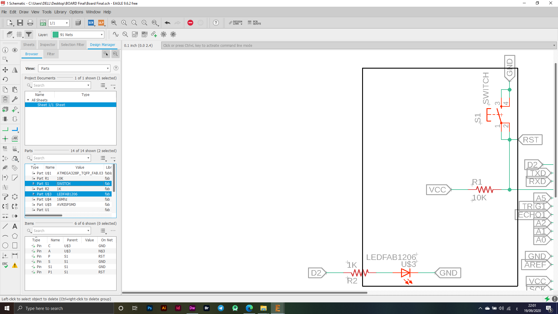
Depending on what the final project requires, I designed the electronic board for my project, and relied on AutoDesk Eagle to design the electronic board, first specifying the pieces that I will use in my final project and then moving on to Eagle for designing the electronic board.
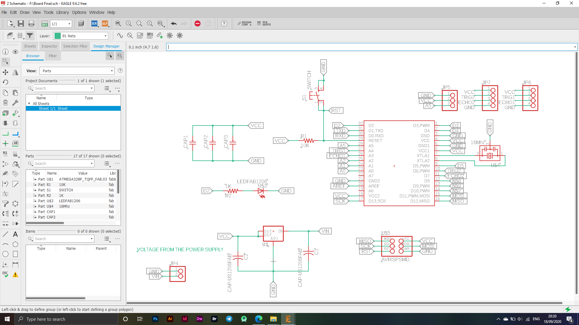
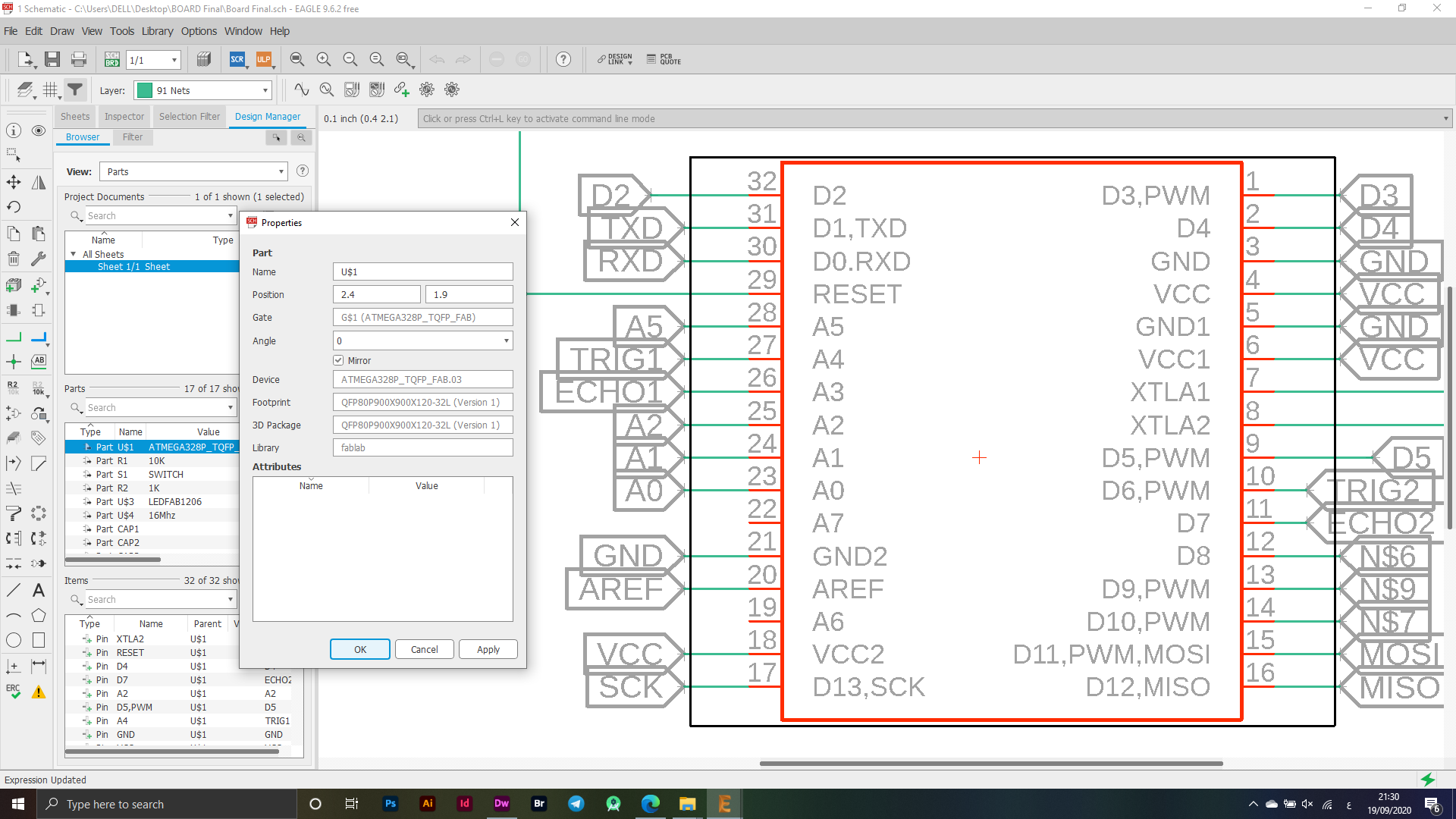
The image above shows the parts used in designing the electronic board for my final project. I used the main piece on which the electronic board "ATMEGA328P_TQFP_FAB.03" relies heavily on the microcontroller.
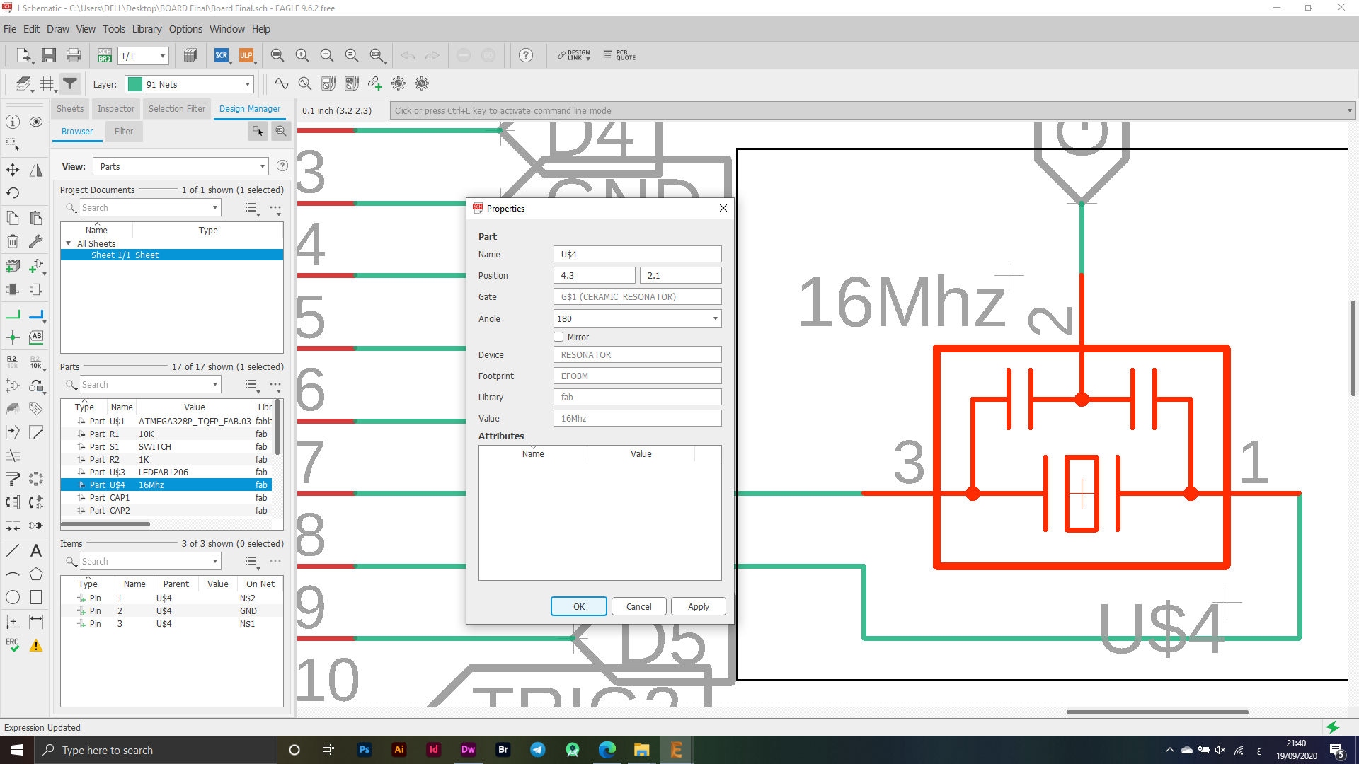
A resonant circuit is a device or circuit that produces resonance. And it naturally oscillates at some frequencies called its resonant frequency. This is because it resonates profusely on this frequency more than on other vibrations. While some programming things happen inside the microcontroller, it depends on this signal that will arrive from this piece.
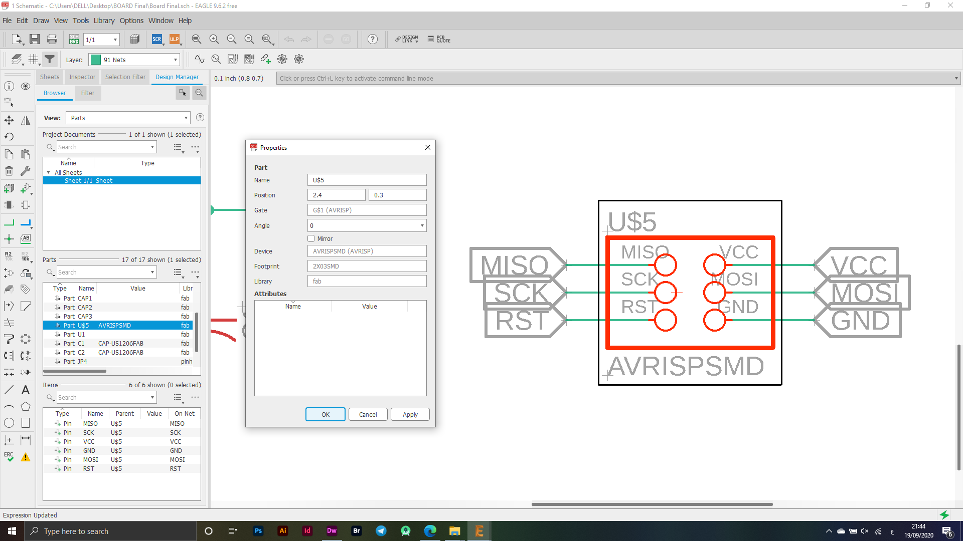
I have added an AVRISPSMD segment to be able to do programming for the ATMEGA microcontroller.
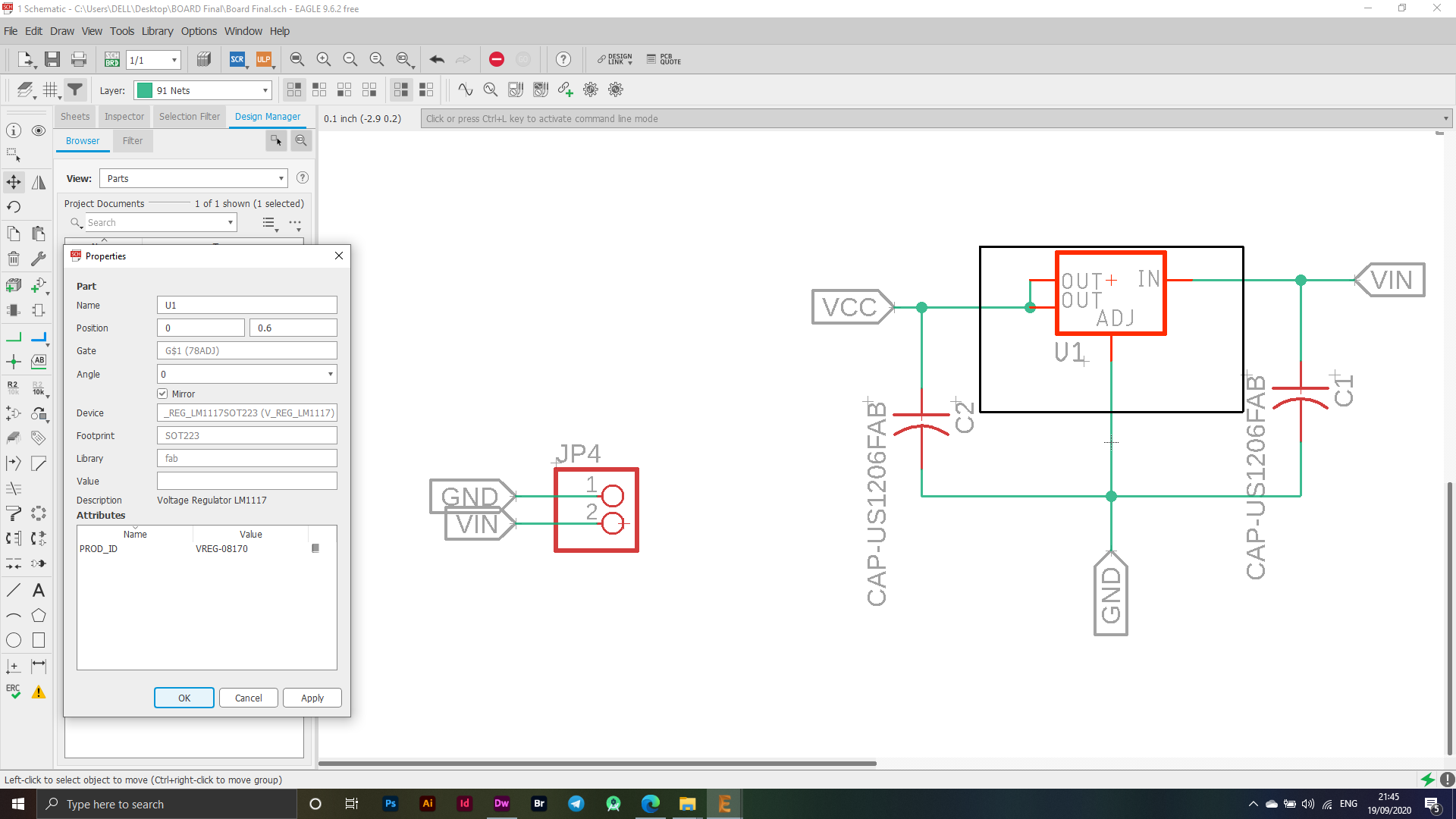
I have been thinking about the power source in my electronic board and found that using a Volatage Regulator is the best solution to support the electronic board with power with a power supply as I used this piece for the purpose of delivering energy within certain limits and converting the electricity that reaches the electronic board from electricity at high values to a specified value on Charging 5V so the power supply will convert the electricity that reaches the electronic board from "AC - DC".
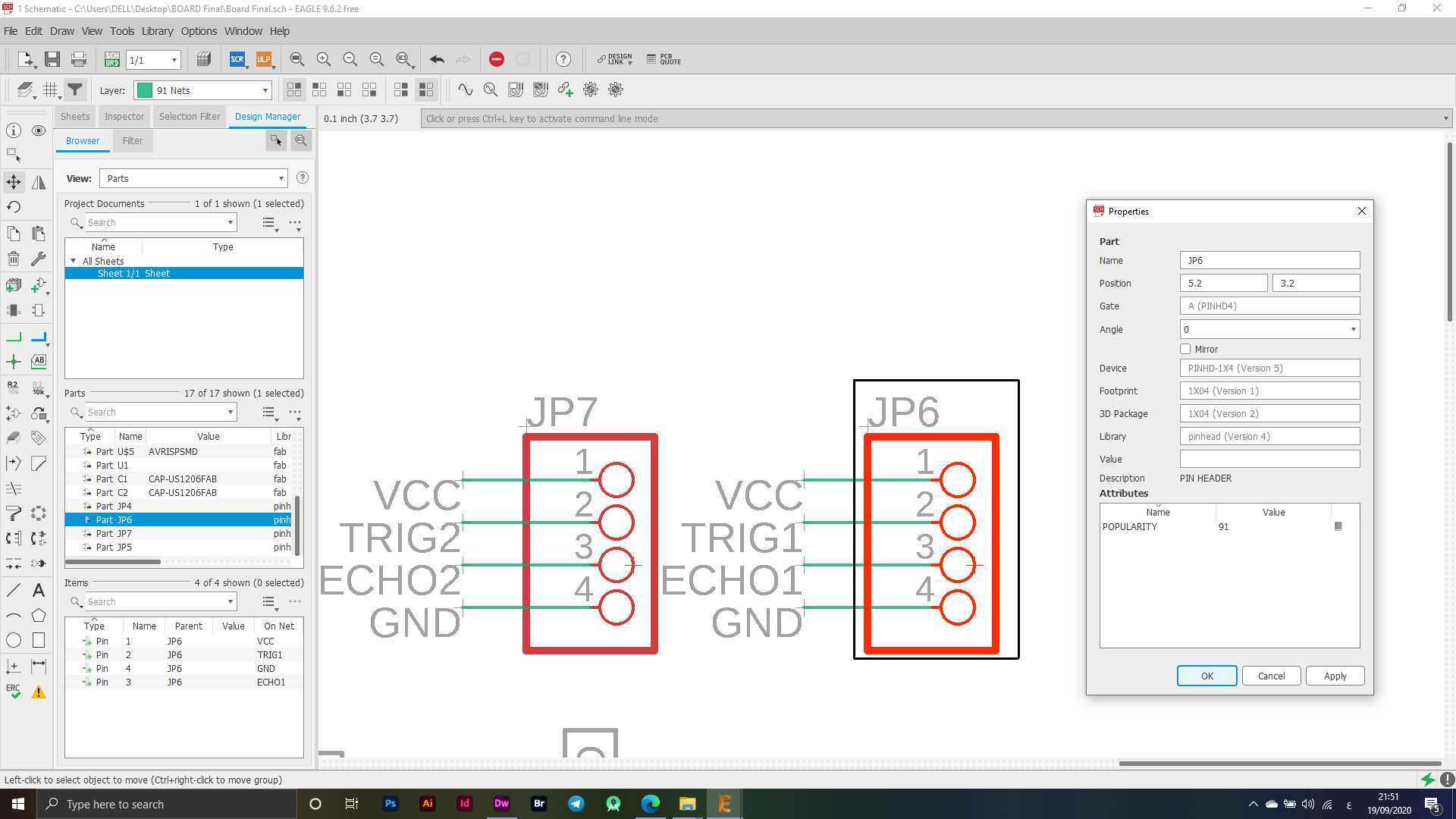
The image below shows my use of the PINS, I used them to connect the UlrtaSonic Sensor to these ports, and the following figure shows how the connection process will be and the names of the ports that will be connected to the Ultrasonic Sensor, which is the body-sensitive device that I will use in my project, as it will be one of the main elements that I will adopt It is also included in the project.
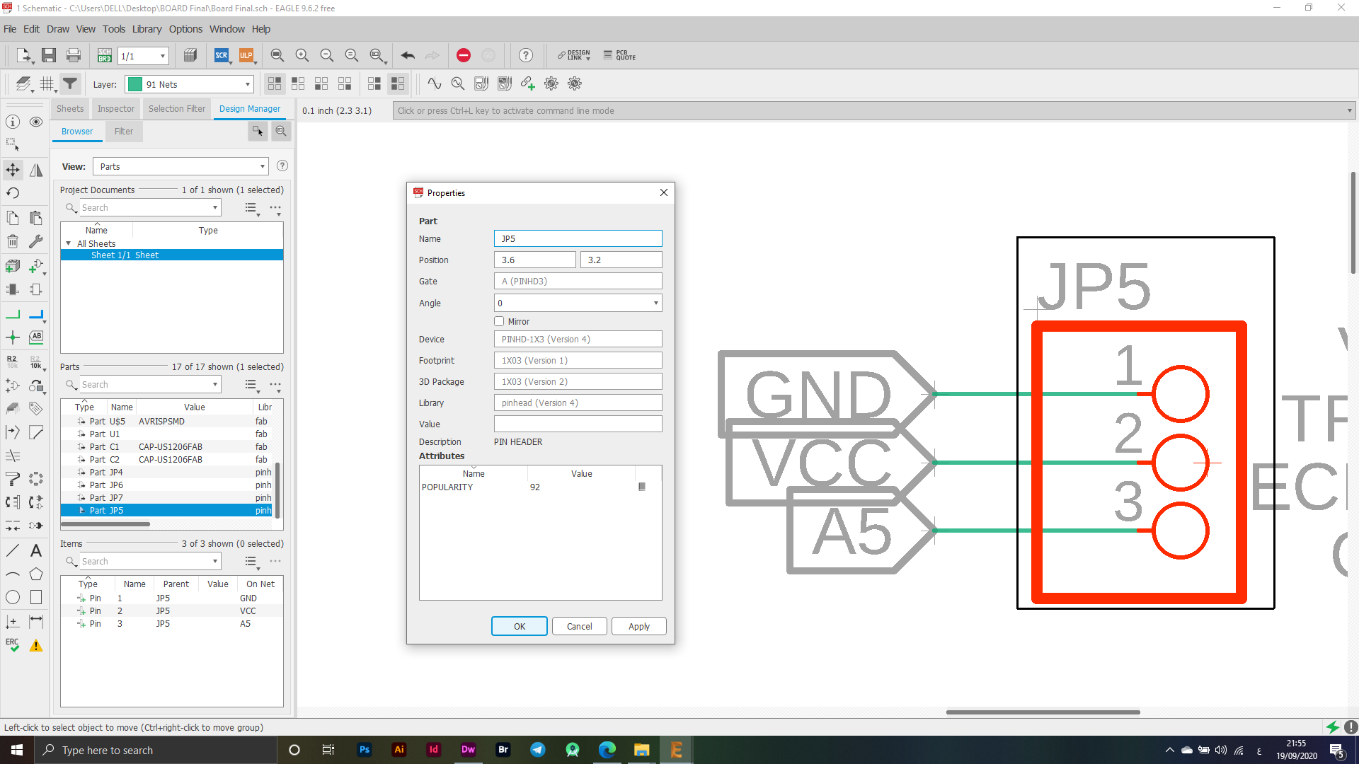
In this part, I will also use the PINS for the Servo Motor device, which I have set up its ports in order, as it will also be one of the most important elements that I will rely on in my project, which will move the device at certain angles to do the required operation of this project.
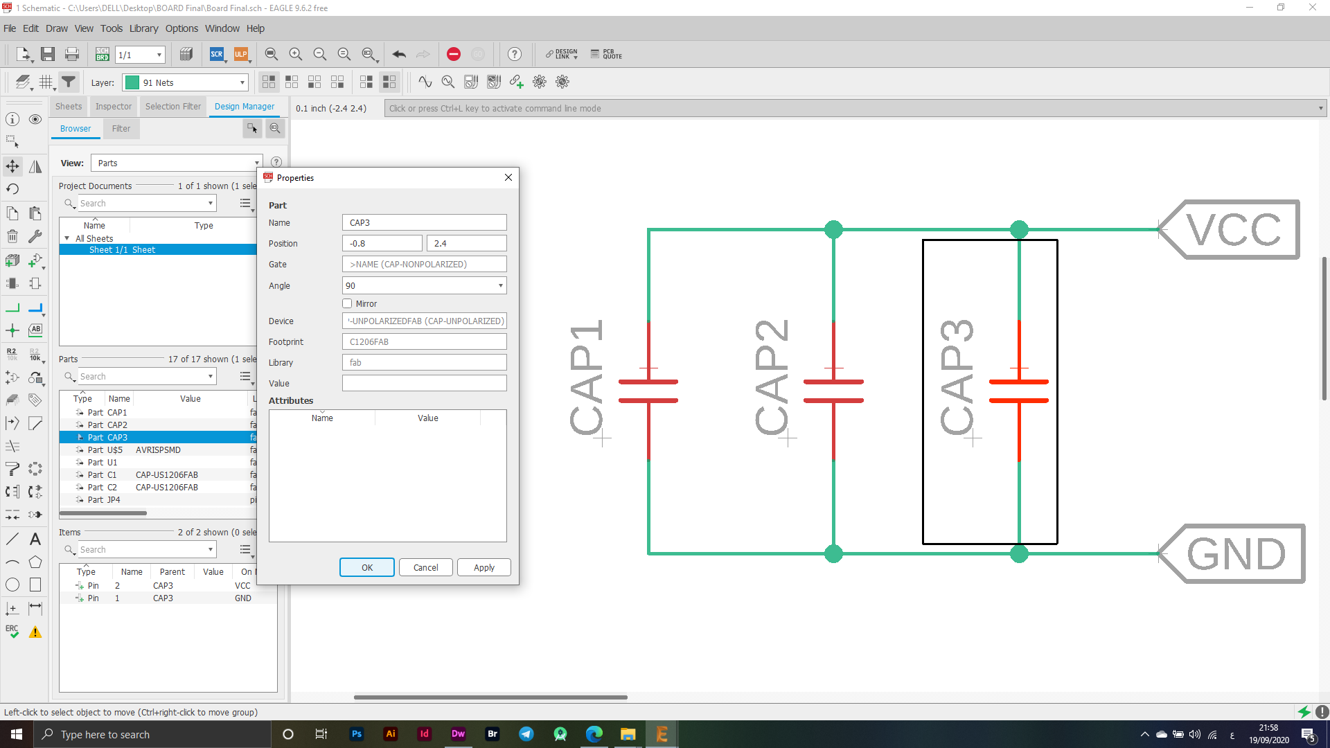
I have used a Capasitor to ensure that data transfer and operation are properly organized.
I used LED & SWITCH on the electronic board to test it when cutting the electronic board, to make sure that it was working properly and to make the operation more easier.
BRD - Board
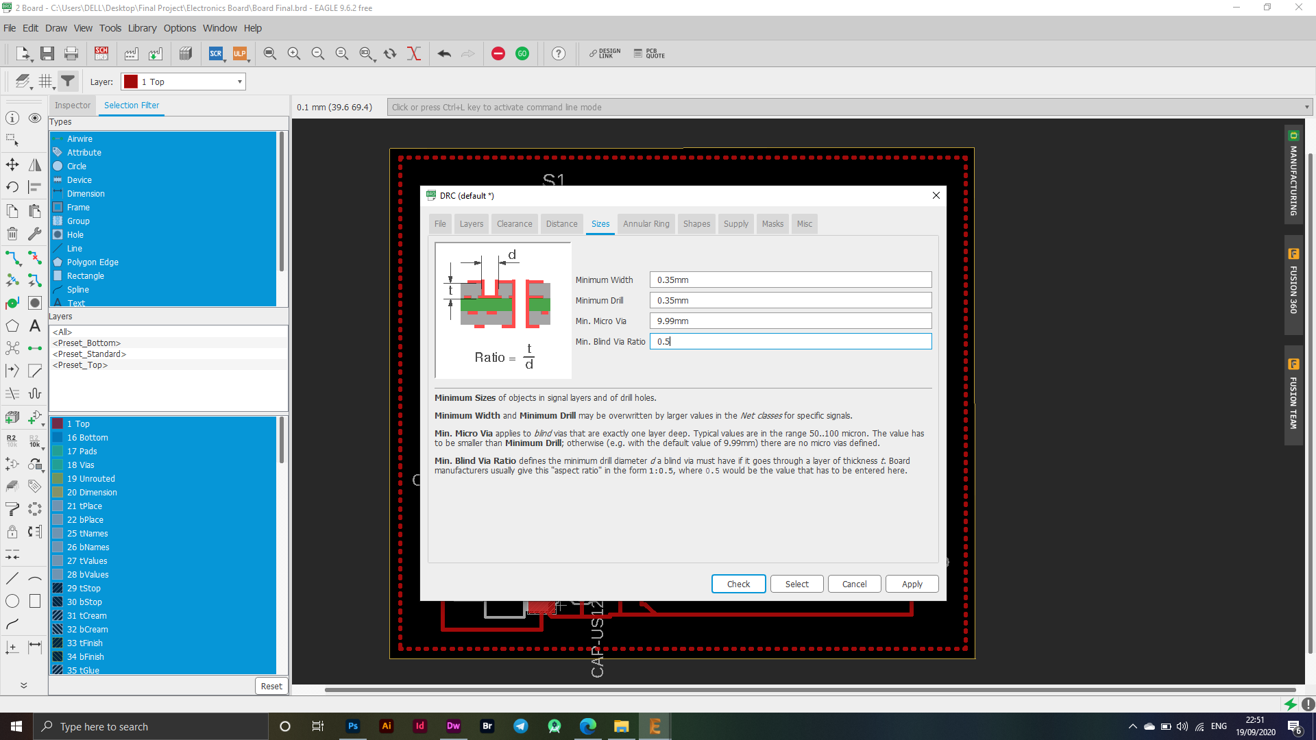
In the beginning, when I moved to the final stage of designing the electronic board, I set some settings from the Tool - DRC option, as these settings are the actual control over the thickness or height of the connections between the electronic parts, and the following pictures show the settings that I used in the process of connecting the board as it is Without adjusting these settings in advance, it can cause many problems, including unstable height or thickness of the connection between the electronic panels, which is what I was facing in the beginning of my use of Eagle.

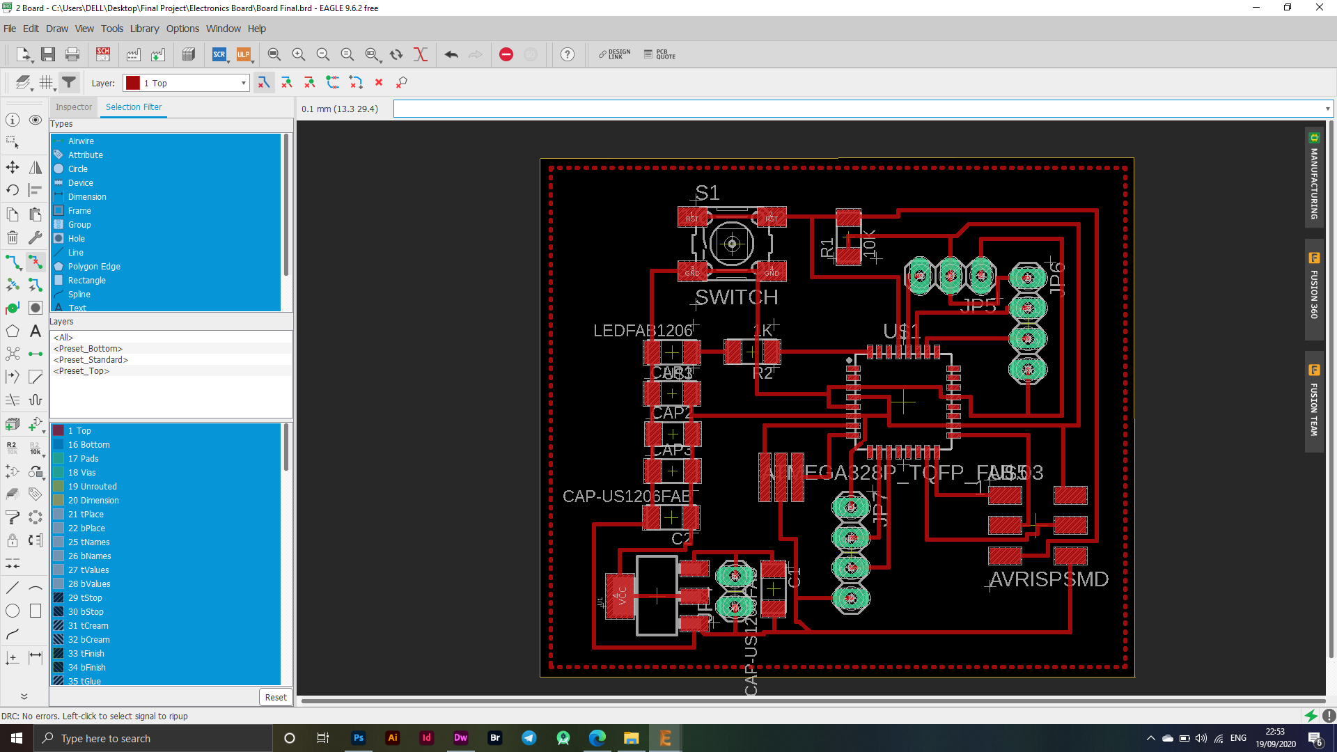
I have made the connections based on many factors, taking into account that all the connections are correct, as I tracked each piece and where I will connect it with the other piece and thus formed an electronic board that I can use in my final project, as shown at the bottom on the left side a sign indicating Indicating that there is no error in this electronic board after verification by the program.
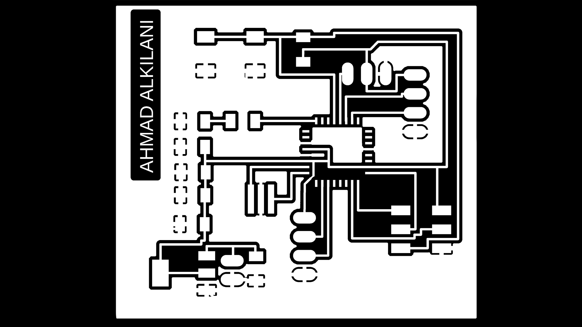
The picture below shows the final shape of my design.
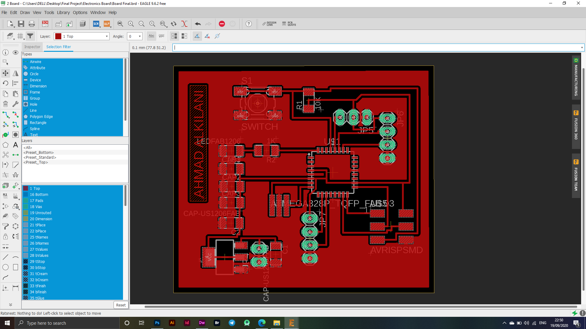
After hiding the layers and keeping some layers showing like Top - Pads, I exported my flap in PNG format using the File - Export - Image menu.
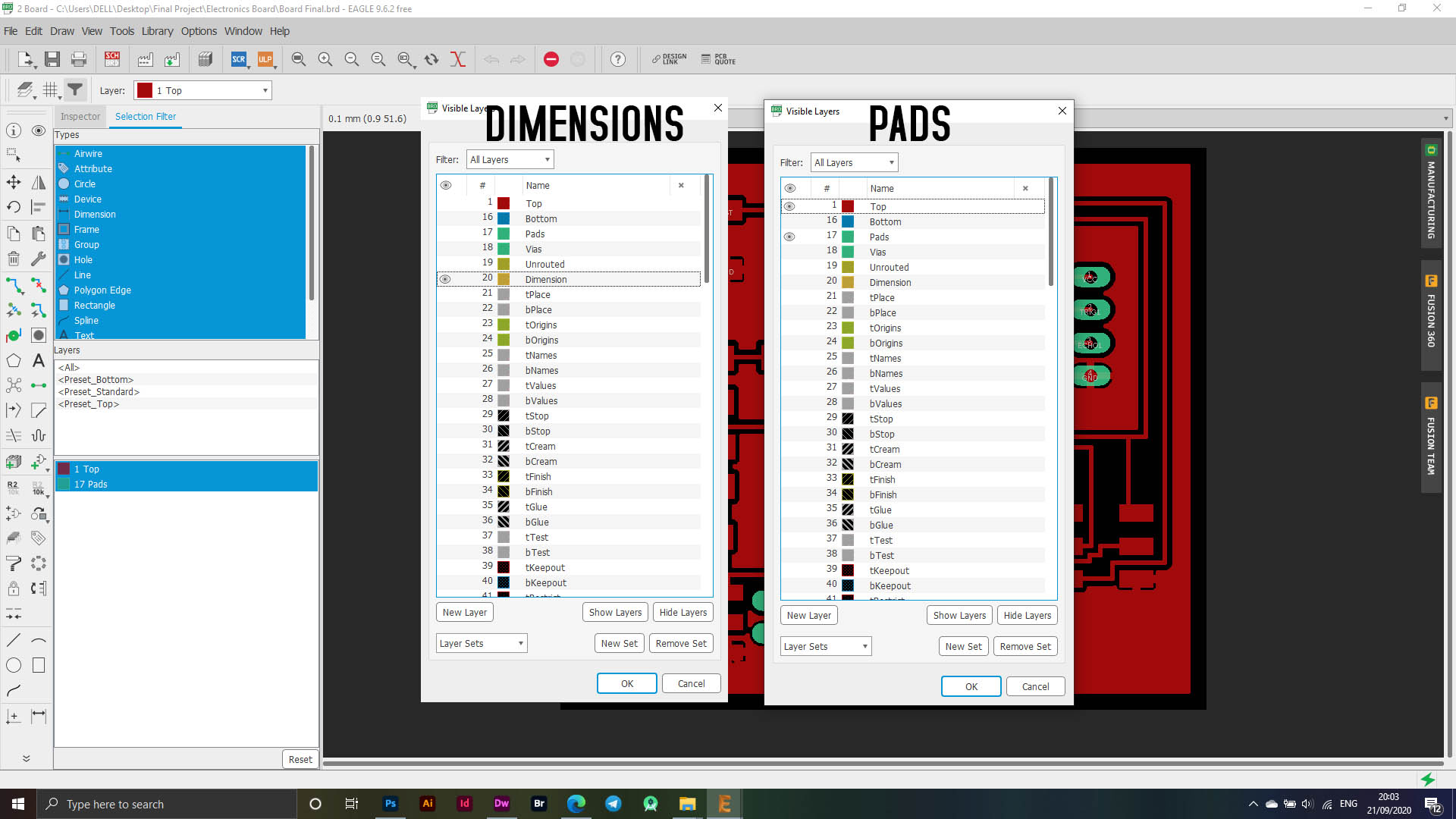
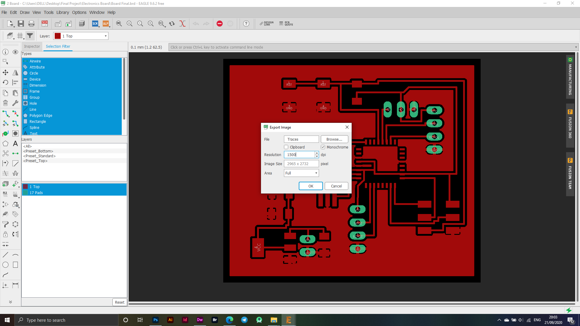
In the following picture, each window indicates the export process. In the first window, PADS, I exported the Traces by hiding all layers and showing the two layers "Pads - Top". In the second window, I exported the Outline by showing the dimensions layer only, and to export it with an image through "File -" Export - Image "The image below shows the settings and the selected dpi.
Fab Modules
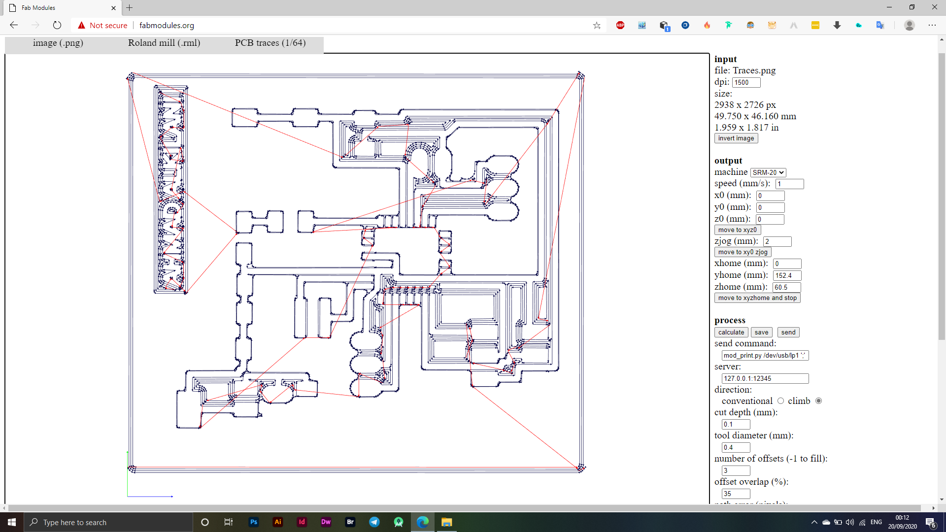
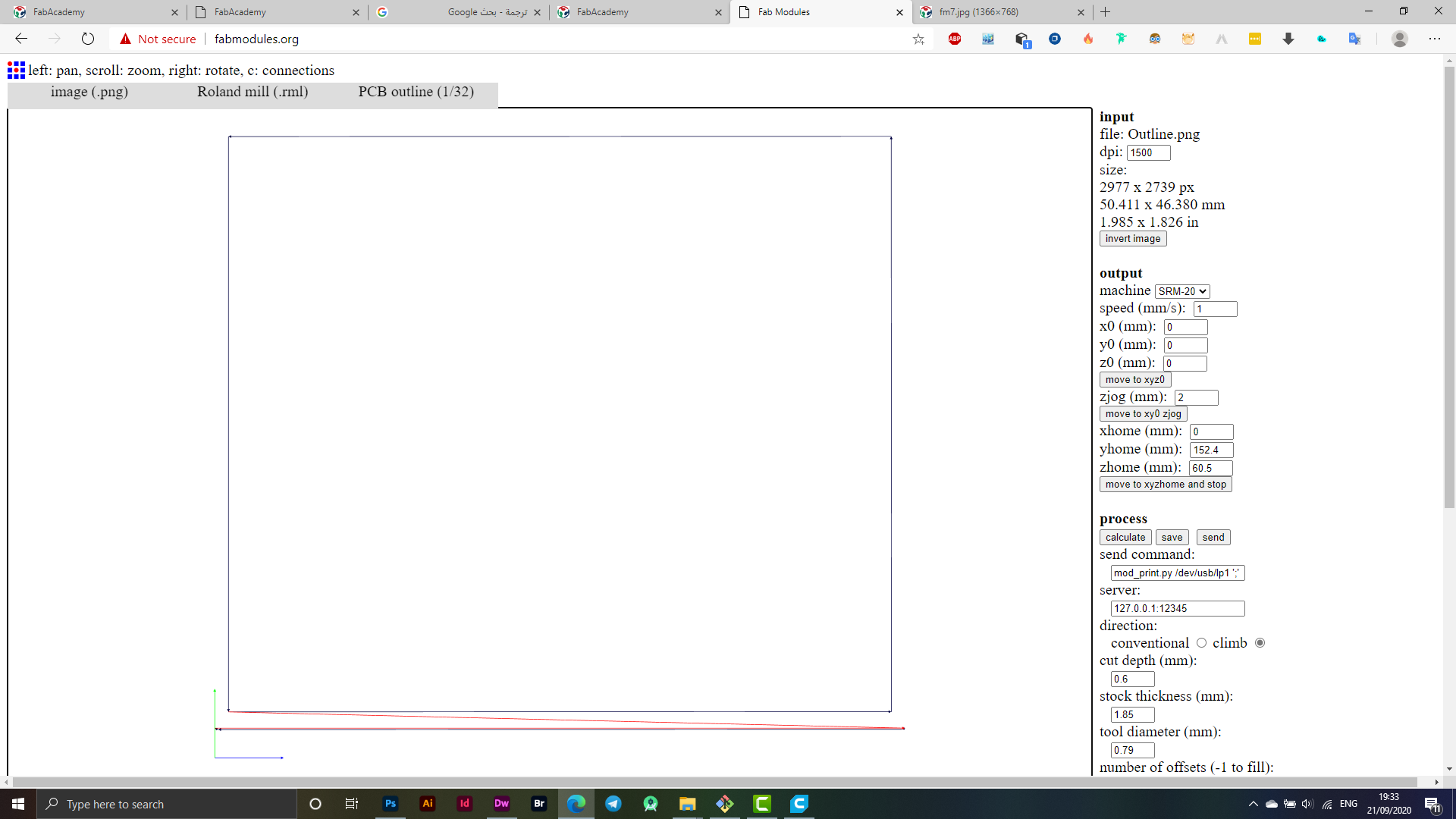
I logged into FabModules which is the site I usually work on to adjust settings while preparing the electronic cutting boards. Initially, I set the settings as shown in the image below:
Traces
Outline
To prepare the files for cutting, I made a save for each file as it will be exported in (.rml) format.
Roland Machine - SRM20
After exporting the files in RML format, I moved to the direct cutting process through the machine, where I zeroed the directions according to the electronic board available to me and in whatever location it was placed, the angle X, Y was zeroed according to the position of the electronic board while the one Z was reset based on making sure that he was able On reaching the board, that is, when doing a test to see whether or not it is connected through a voltmeter, the voltmeter must signal that the poles are connected to each other so that we can make sure that the operation will go well.
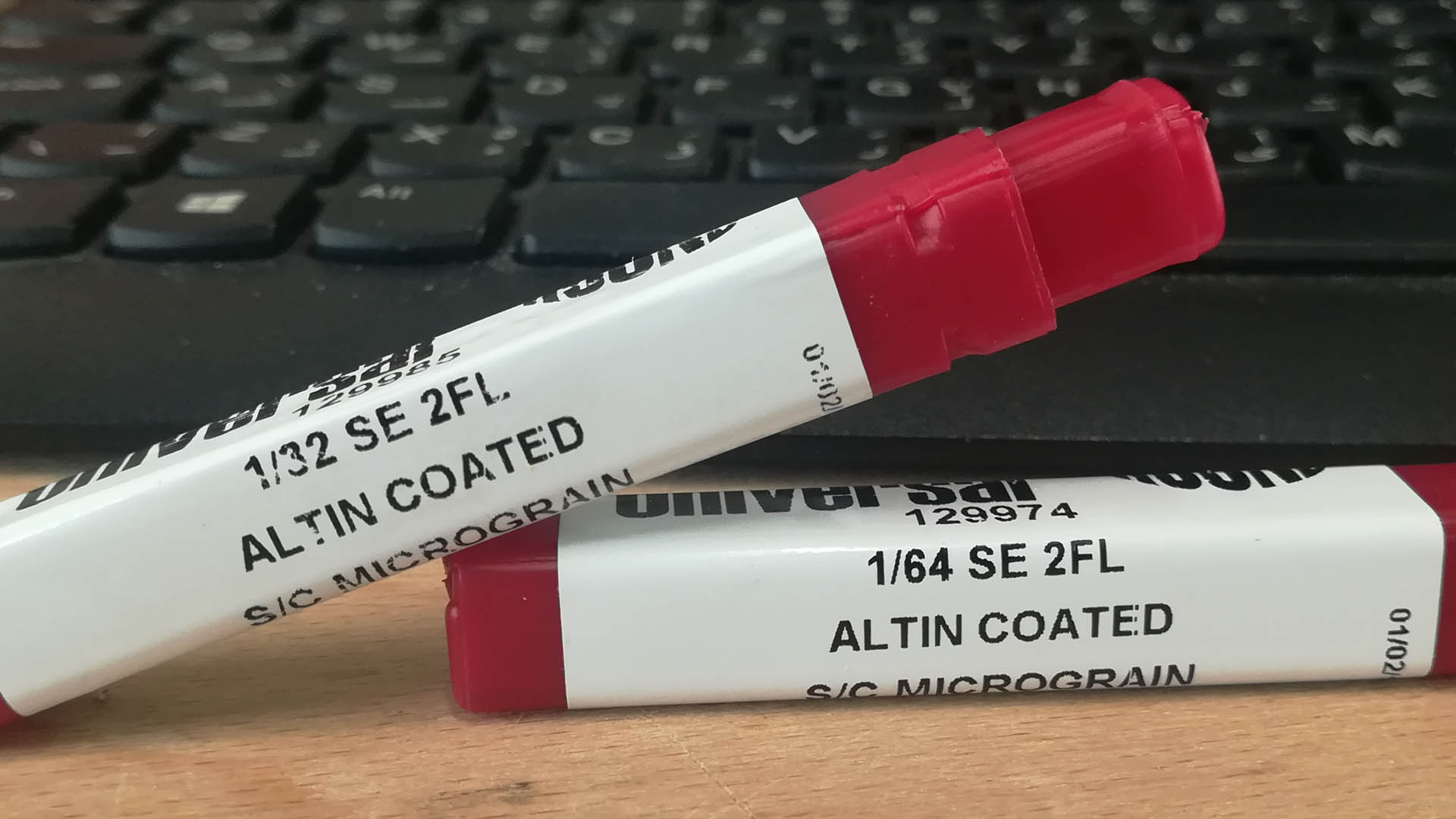
I used an End Mill 1/64 bit for my Traces cut, I used End Mill 1/32 for an Outline cut, the following image shows more information.
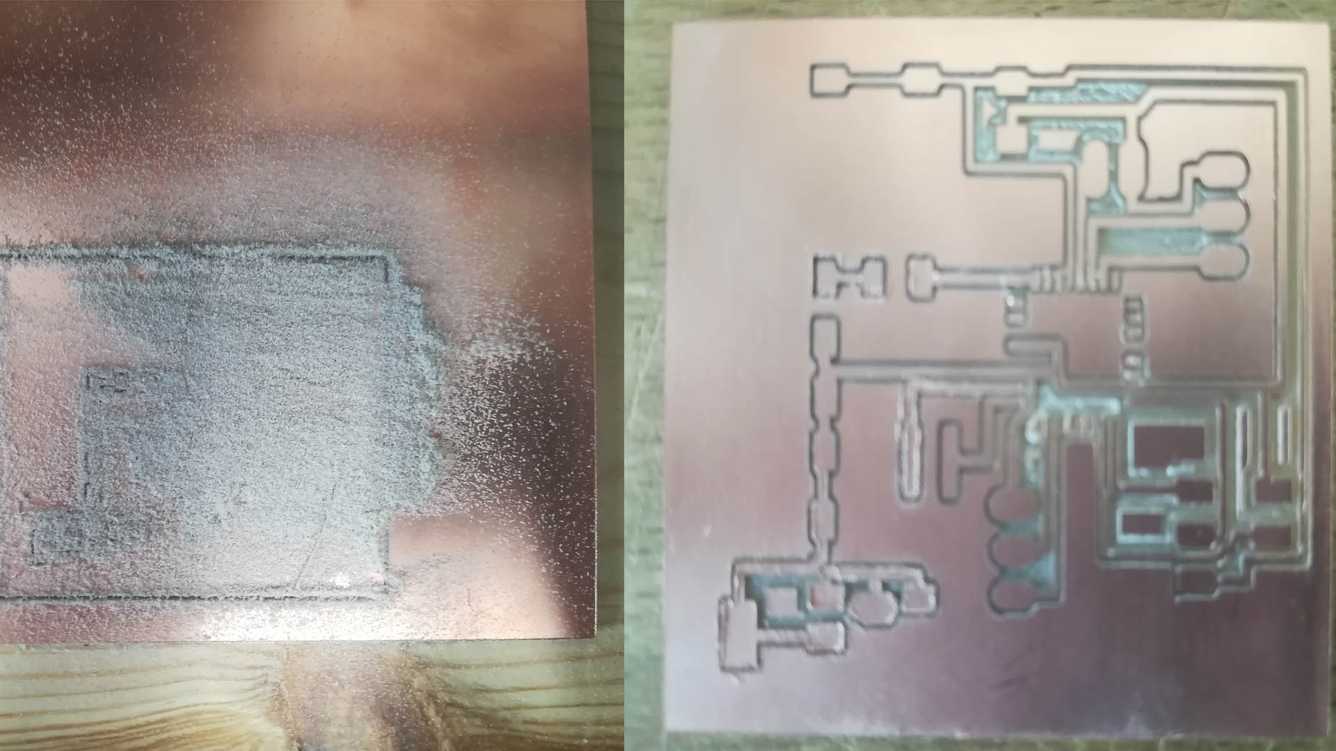
The image below is the final look of your design.
Soldering
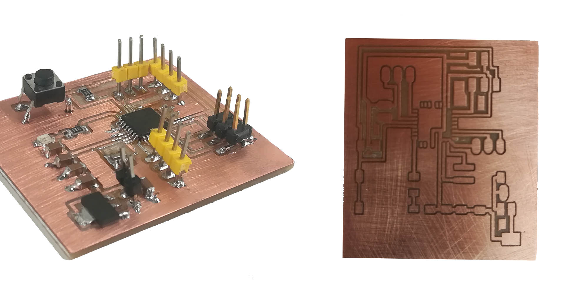
I welded the parts and as the picture below shows the welding process, the process of welding the parts took about an hour, in addition to that I encountered a problem during the process of programming the electronic board as I performed a wrong operation when welding the Resonator piece, which led to two ports contacting each other, and after making sure that it is the place Faulty I took apart the piece and re-soldered again, it was a really fun process.
| Components | Quantity |
|---|---|
| Atmega328p | 1 |
| Ultrasonic Sensor | 2 |
| Servo Motor | 1 |
| Button | 1 |
| Voltage Regulator | 1 |
| 16Mhz Crystal | 1 |
| LEDs | 1 |
| AVR ISP | 1 |
| Pin Headers | 1×2 - 1×3 - 2×4 |
| Capacitors | 5 |
| Resistors | 3 |