- Group Assignment:
- probe an input device's analog levels and digital signals
- Individual Assignment:
- measure something: add a sensor to a microcontroller board
that you have designed and read it
- measure something: add a sensor to a microcontroller board
- Link to the group assignment page
- Document what I learned from interfacing an input device(s) to microcontroller and how the
physical property relates to the measured results - Document my design and fabrication process or link to previous examples
- Explain the programming process/es I used
- Explain problems and how I fixed them
- Include original design files and source code
- Include a ‘hero shot/video’ of my board

Group Assignment
An input device is something that represent a information in electrical signals that could be processed by the MCU. Sensors are a big category of input devices that can detect changes in physical quantities, such as light, temperature, current,.. etc, and give either analog or digital representation to that quantity.
If a sensor is provides an analog signal, this means that it can measure a range of readings on a scale, such as temperature, and if it provides a digital signal, it generally means that it tells you only two different states, like if it's above a certain temperature level or below.
In this assignment I would measure the output of the LM35 Analog temperature sensor.
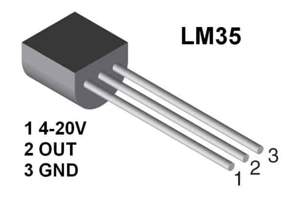
The sensor has three pins: VCC, GND, and the OUT pin that gives an analog voltage proportional to the ambient temperature.
According to the datasheet, the sensor gives a linear output of 10 mV for each degree Celsius. This means that if the ambient temperature is 25 °C, the OUT pin would give a reading of 250mV or 0.25V
I connected the sensor to 5V and GND on a breadboard like the pinout said.
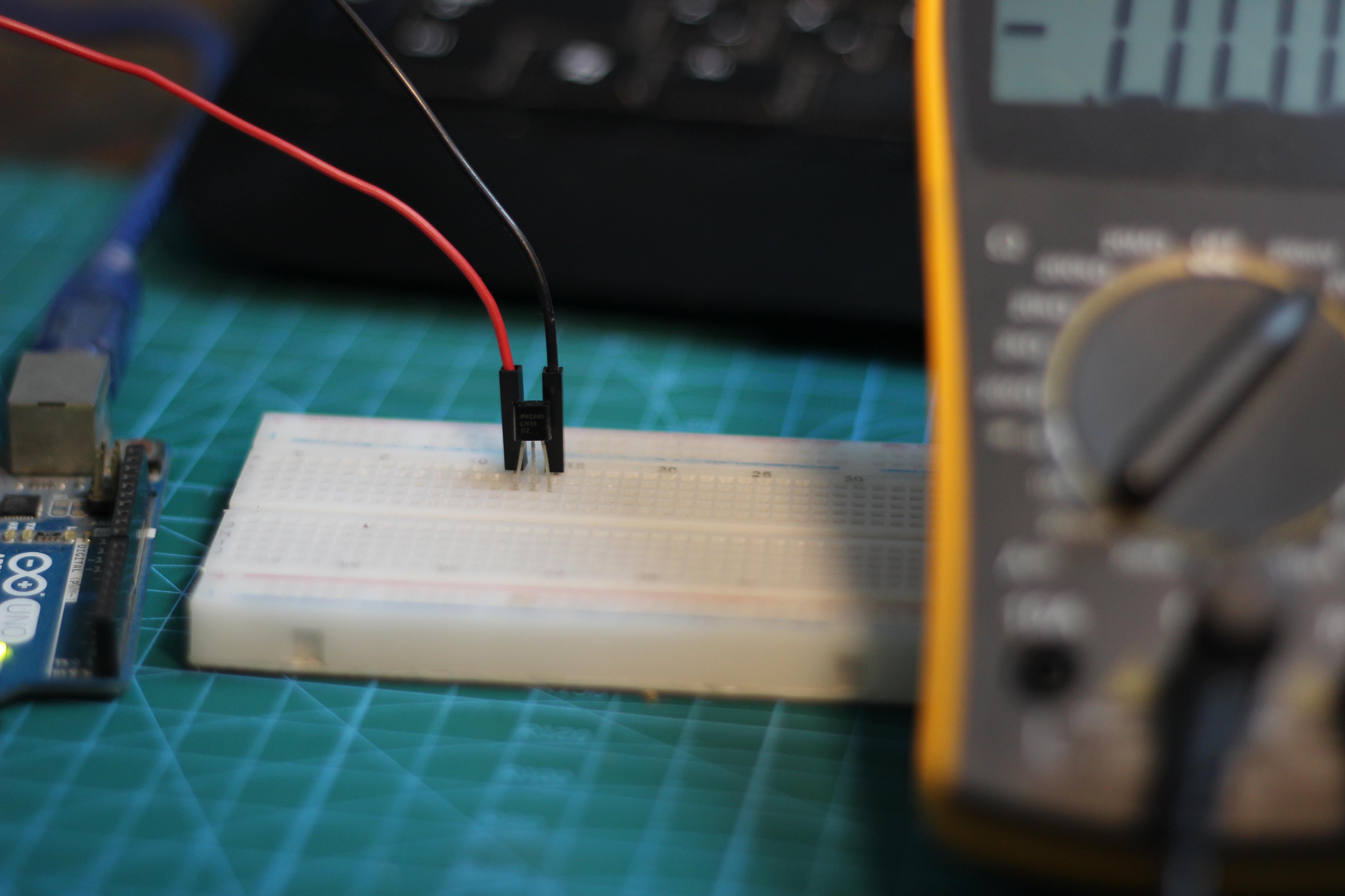
I then measured the output using the AVO meter, and I was 0.269 volts. This means that the ambient temperature was 26.9°C, and this somehow matched the number the A/C was set to.
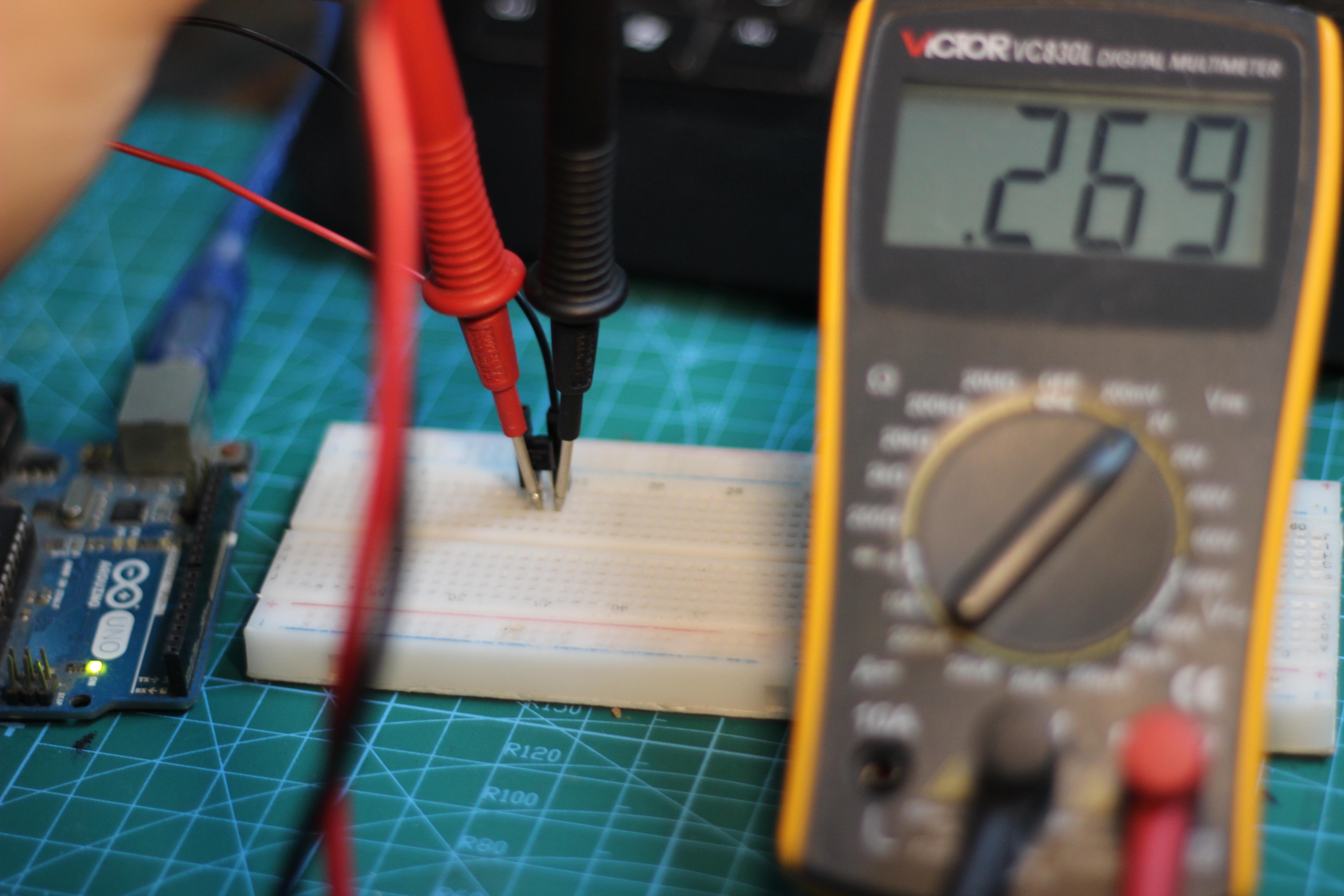
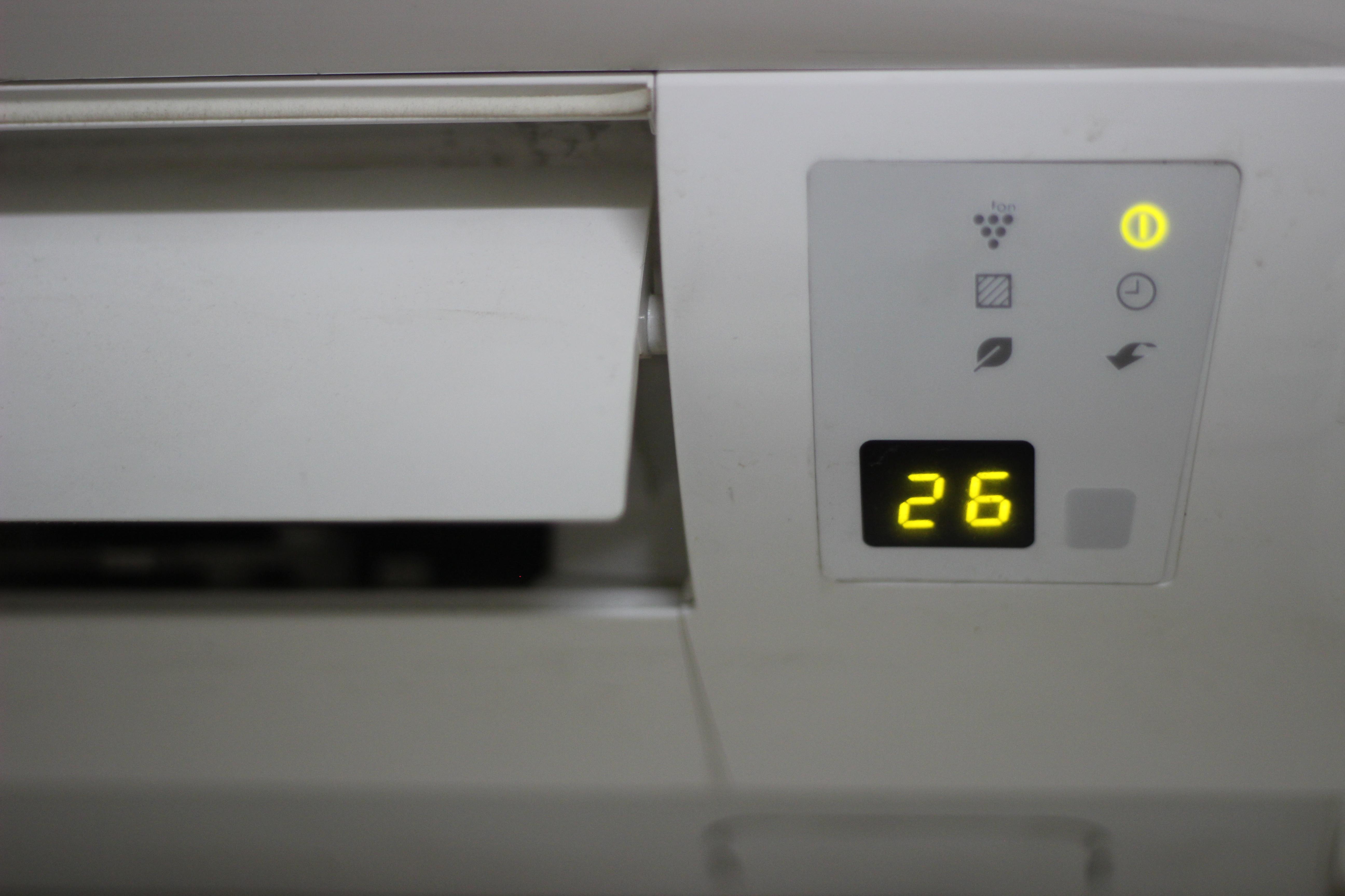
The readings were pretty close, but I think the difference came from the fact that I was sitting relatively far from the A/C, which could justify the difference in readings between the A/C and the sensor.
Understanding HC-SR04
The HCSR04 is an Ultrasonic Sensor that uses sonar to determine the distance to an object. It consists of a transmitter and receiver. When the (trig pin) gets an electrical signal, the transmitter sends a sound signal: a high-frequency sound that can't be heard by humans. When the sound signal finds an object, it is reflected and the receiver receives it and changes it into electrical signal on the (echo pin).
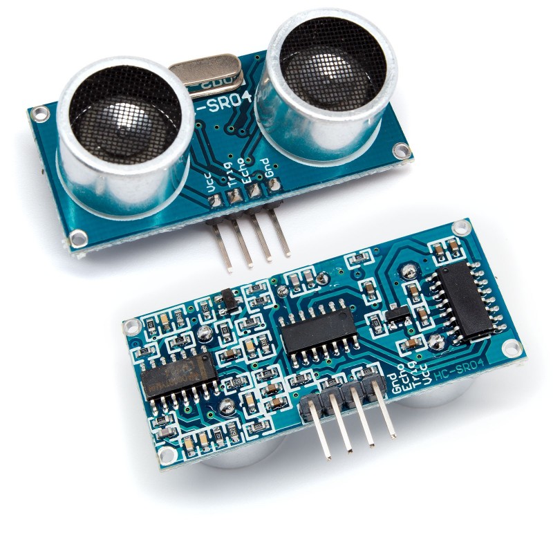
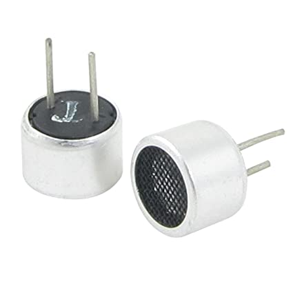
The core components of the Ultrasonic Sensor are the TX and RX Pair
The module has the following specs are:
- Measuring Angle: 30 degree
- Resolution : 0.3 cm
- Ranging Distance : 2cm – 400 cm
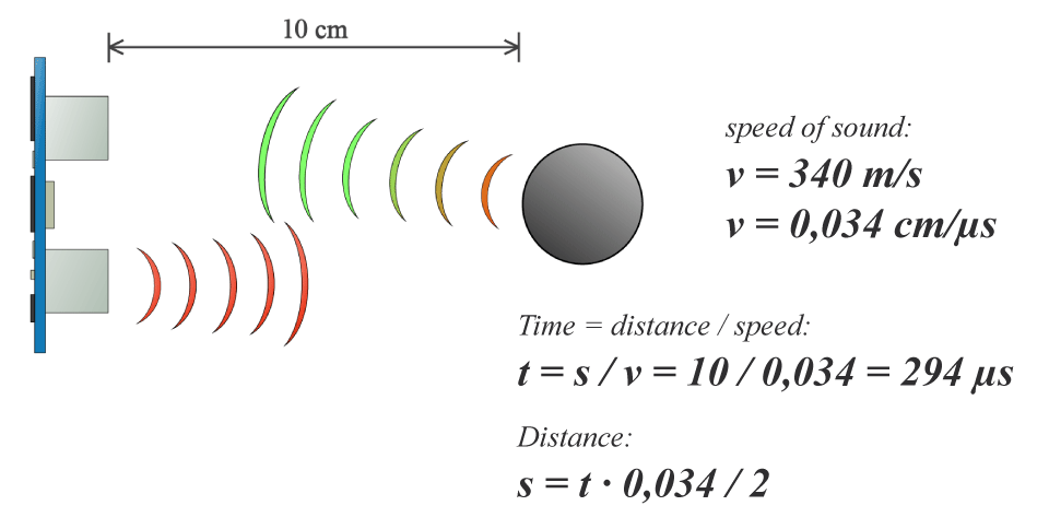
In order to measure the distance the Trig on should be at High State for 10 µs. That will send out an 8 cycle sonic burst which will travel at the speed sound and it will be received in the Echo pin. The Echo pin will output a signal when the sound comes back again.
Measuring the delay time between the sending and receiving can indicate the distance of the object knowing that Time = Distance / Speed and the speed of sound is 340 m/s
HC-SR04 PCB Design
I got bored from designing ATtiny boards : D I decided to make a general design with all the common pins to be used in communication protocols, so that I would be able to use it in the coming assignments.
The main specs for the board I decided were:
- I would use the internal crystal
- I would have a voltage regulator, so that I could drive the board from a battery
- I would keep the ISP header so that I would be able to change the code easily
- I would put an LED so that I can use it for debugging.
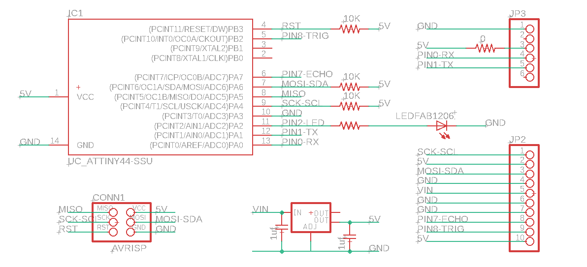
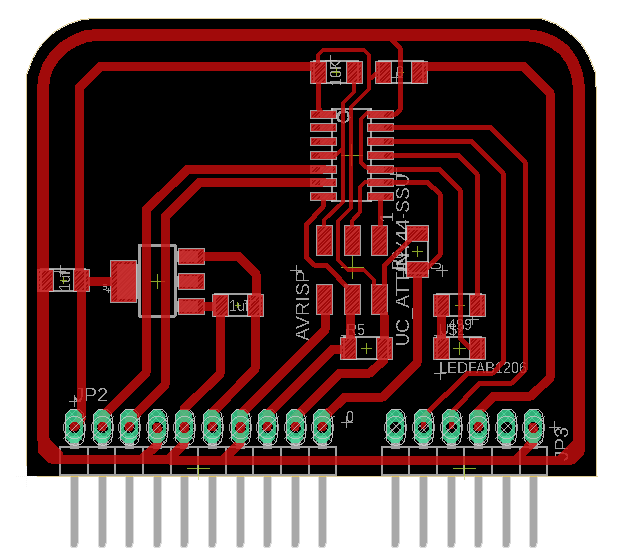
I used eagle to create the PCB. I started with the schematic:
- I had a pin header with 6 pins for FTDI
- Another pin header with 10 pins, for:
- 2: 5V and GND
- 2: Battery Volt (12V) & GND
- 2: I2C Pins
- 4: Ultrasonic Pins (VCC, GND, Trig, and Echo)
- I had the ISP header
- A 5V voltage regulator
- and ofcourse the ATtiny44
I made the layout with DRC of 0.45mm distance between traces.
I milled the board using modela MDX-20 like I did in the electronics production week.
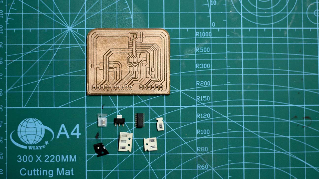
The BOM for the board is:
| Part | Quantity |
|---|---|
| ATTINY44A-SSU-ND IC AVR MCU 4K 10MHZ 8SOIC | 1 |
| RES 499 OHM 1-4W 1% 1206 SMD | 1 |
| RES 10.0K OHM 1-4W 1% 1206 SMD | 3 |
| RES 0.0 OHM 1-4W 1% 1206 SMD | 1 |
| 6 Positions Header Connector 0.100" SMD | 1 |
| SMT RT Angle Male Header 0.1" (36pos) | 1 |
| LED GREEN CLEAR 1206 SMD | 1 |
| CAP CER 1UF 50V X7R 10% 1206 | 2 |
| LM1117 5V Voltage Regulator | 1 |
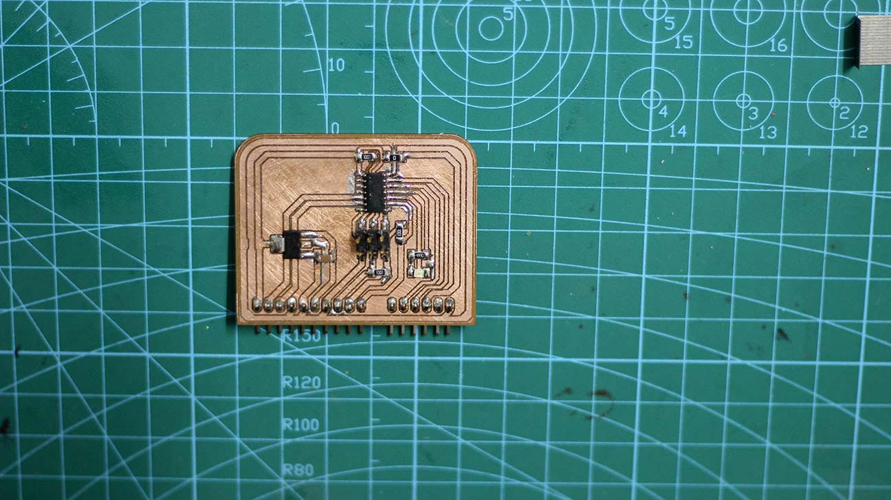
This is after I soldered everything in place.
Now the next step is to write the code.
HC-SR04 PCB Testing
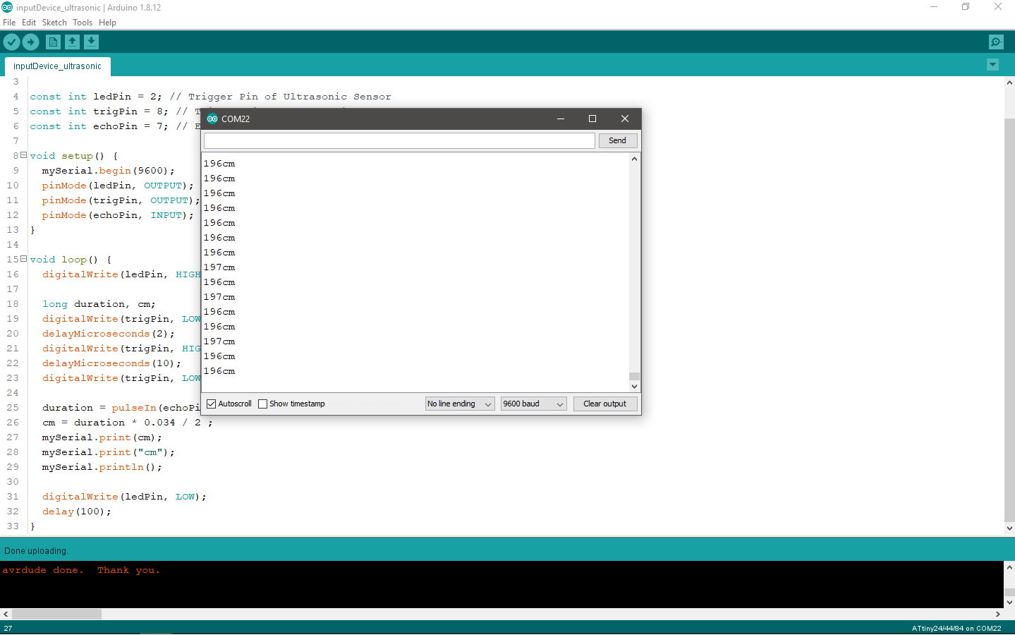
The code is based on the algorithm mentioned above. The loop function triggers the
ultrasonic to send the a sound wave, then waits for the signal to return back using the
pulseIn() function. The distance is calculated using the equation mentioned before
as well.
#include <SoftwareSerial.h>
SoftwareSerial mySerial(0, 1); // RX, TX

const int ledPin = 2; // Trigger Pin of Ultrasonic Sensor
const int trigPin = 8; // Trigger Pin of Ultrasonic Sensor
const int echoPin = 7; // Echo Pin of Ultrasonic Sensor

void setup() {
    mySerial.begin(9600);
    pinMode(ledPin, OUTPUT);
    pinMode(trigPin, OUTPUT);
    pinMode(echoPin, INPUT);
}

void loop() {
    digitalWrite(ledPin, HIGH);

    long duration, cm;
    digitalWrite(trigPin, LOW);
    delayMicroseconds(2);
    digitalWrite(trigPin, HIGH);
    delayMicroseconds(10);
    digitalWrite(trigPin, LOW);

    duration = pulseIn(echoPin, HIGH);
    cm = duration * 0.034 / 2 ;
    mySerial.print(cm);
    mySerial.print("cm");
    mySerial.println();

    digitalWrite(ledPin, LOW);
    delay(100);
}
After uploading the code, the output distance is displayed on the serial monitor. Note that if the sensor has nothing to measure the distance would be displayed in random big numbers.
Here's a video demo for the results: