- Group Assignment:
- Compare as many tool options as possible
- Individual Assignment:
- Link to the group assignment page
- Document my process
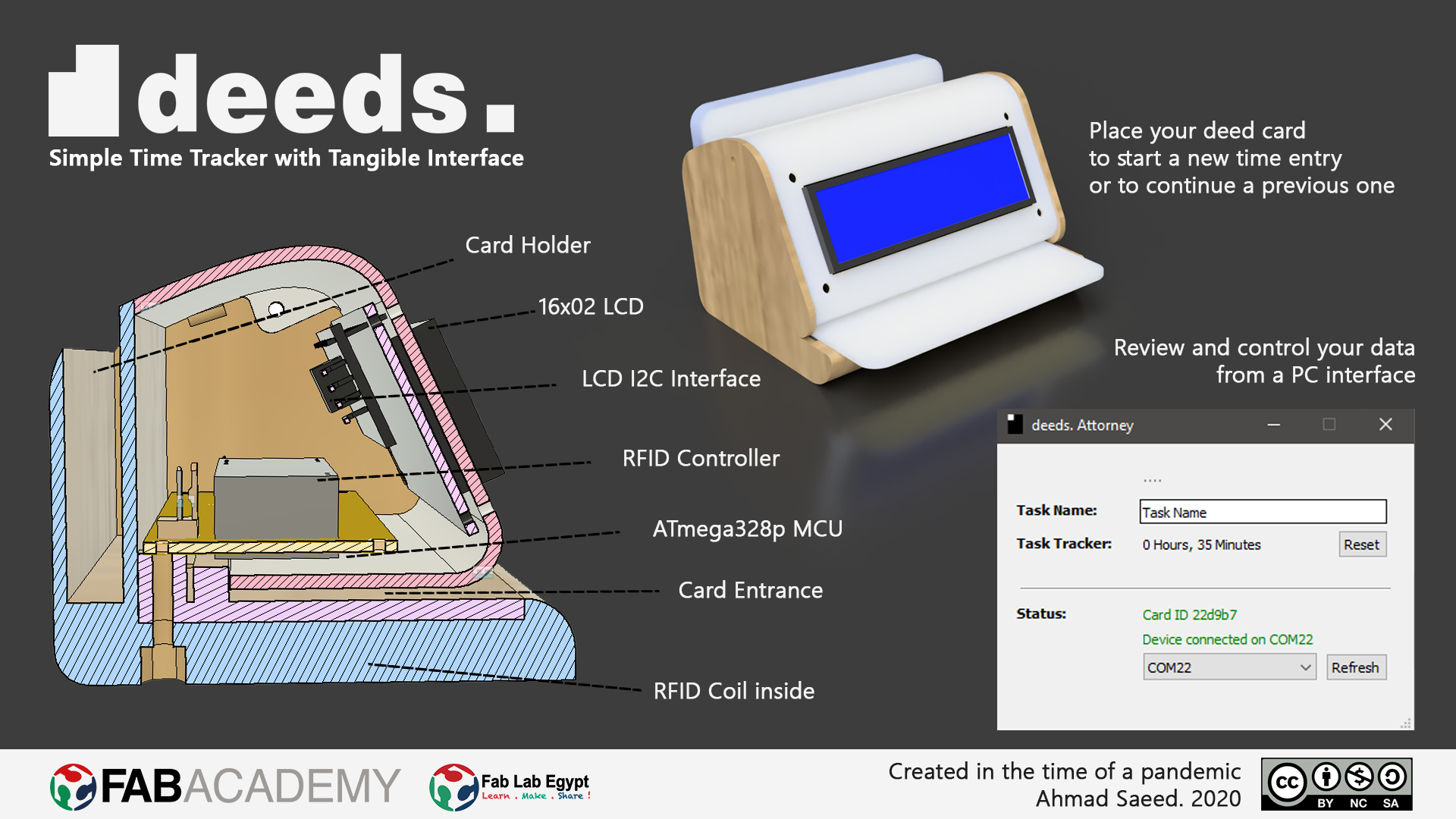
- Explaine the UI that I made and how I did it
- Outline problems and how I fixed them
- Include original code (or a screenshot of the app code if that's not possible)
- Include a ‘hero shot/video’ of my application running with my board
Group Assignment
Google says that "A GUI displays objects that convey information, and represent actions that can be taken by the user. The objects change color, size, or visibility when the user interacts with them". I thought that if I tried to convey info, represent actions, and change the properties of the objects I would have mastered the basics of the tools that I was going to use.
I decided to build a simple stopwatch using both VB.NET and App Inventor. A simple stopwatch contains
- A Label for showing time
- A Start button
- A Stop button
- A Reset button
First I tried using Visual Studio to design and program my GUI.
To create a GUI for windows you need to select Windows Forms App
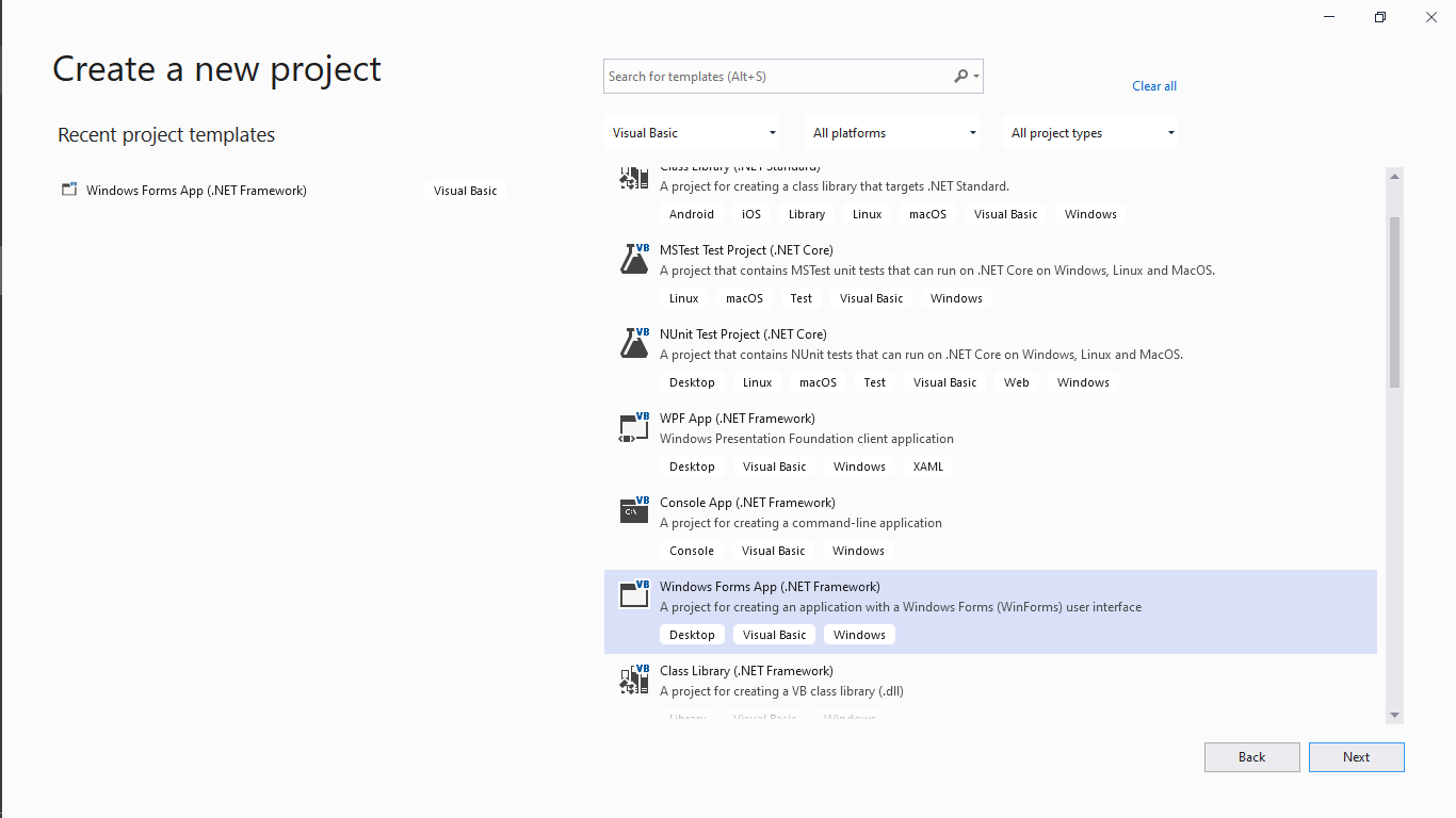
Building a GUI in Visual Studio was pretty simple; just drag and drop the elements from the Toolbox on the left, then change each Item properties from the Properties panel on the bottom right of the screen.
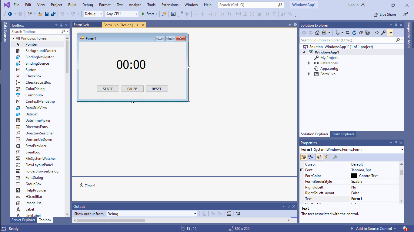
There is an element called Timer which is basically needed to give the sense of time to the application, because it can be linked to a function that can be executed each time the timer interval is reached. I set the interval for the timer to be 1000ms in order to have my code executed each second.
After finishing the design, I went to write the basic code for the buttons and the timer.

The code is straightforward:
- There are two global variables for storing the minutes and the seconds
- When the timer is enabled it increases the seconds and shows the new time on the label
- The Start button just enables the timer
- The Stop button disables the timer
- and finally the Reset button resets the global variables and changes the text on the label.
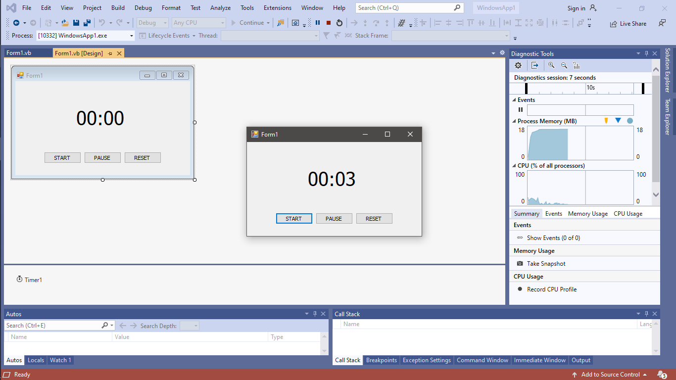
I ran the code and the application worked well.
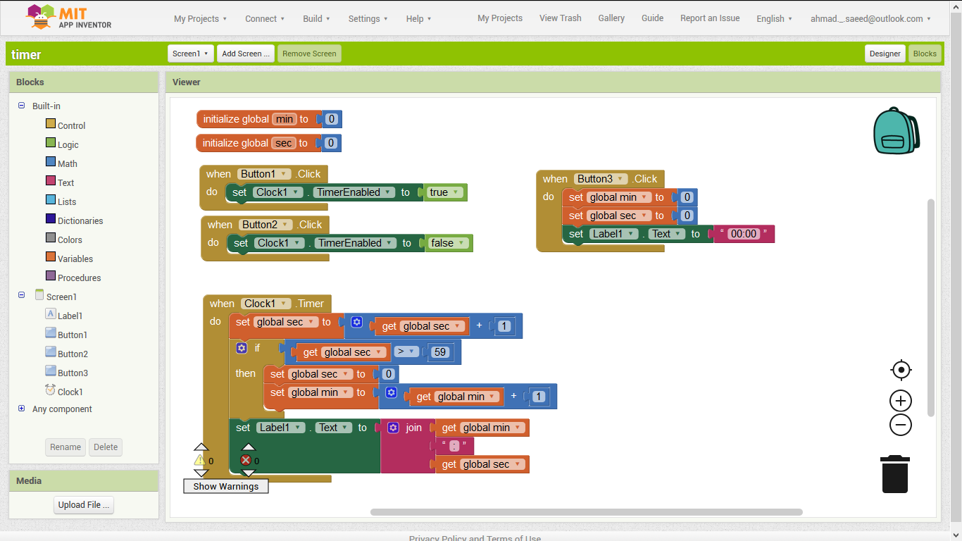
The second trial would be in App Inventor. I created the roughly the same GUI using the same element; except for the name of the Timer element was named Clock in App Inventor.

I implemented the same previous algorithm but using blocks this time.
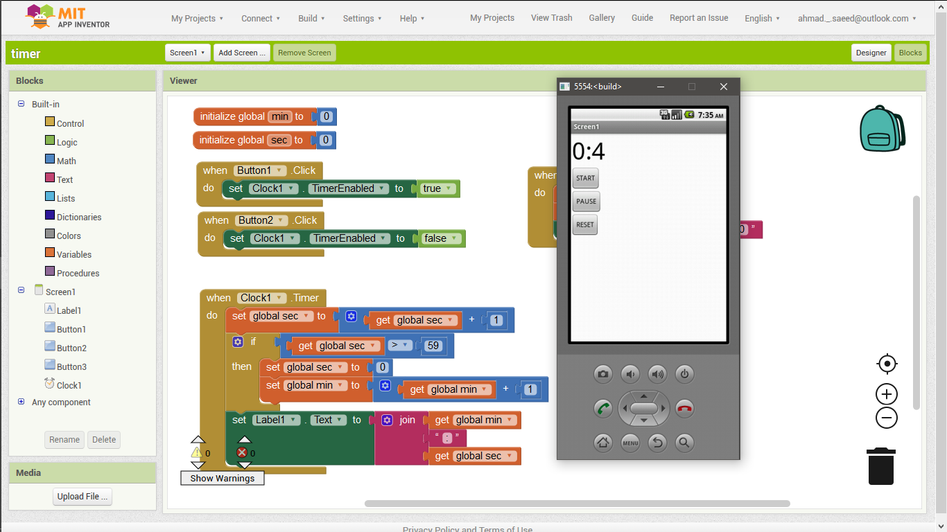
In order to test the code in App Inventor, I had to install the Android Emulator.

After that the application ran nicely.
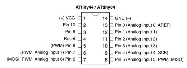
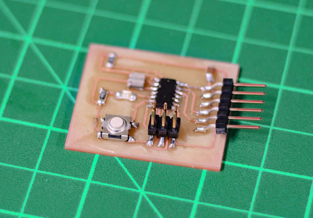
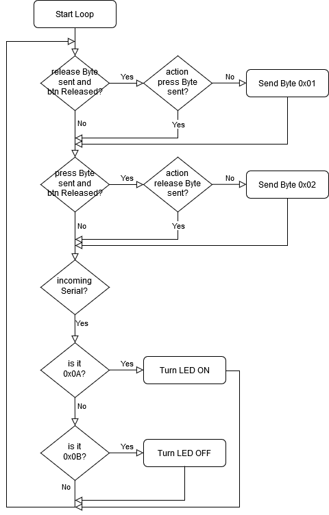
Preparing the Board
- LED on pin 7
- Button on pin 8
- 0x01 - Button pressed
- 0x02 - Button Released
- 0x0A - Turn LED ON
- 0x0B - Turn LED OFF
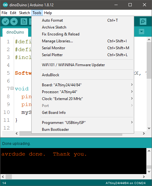
I also used the SoftwareSerial library because the ATTiny44 doesn't have hardware UART interface.
#define btn 7
#define led 8
#include <SoftwareSerial.h>

SoftwareSerial mySerial(0, 1); // RX, TX
bool pressed = false;

void setup() {
  pinMode(btn, INPUT_PULLUP);
  pinMode(led, OUTPUT);
  mySerial.begin(9600);
}

void loop() {
  if (digitalRead(btn) == LOW && pressed == false)
  {
    pressed = true;
    mySerial.write(byte(0x01));
    delay(100); // debouncing
  }
  if (digitalRead(btn) == HIGH && pressed == true)
  {
    pressed = false;
    mySerial.write(byte(0x02));
  }

  if (mySerial.available())
  {
    byte msg = mySerial.read();
    if (msg == 0x0A) digitalWrite(led, HIGH);
    if (msg == 0x0B) digitalWrite(led, LOW);
  }
}
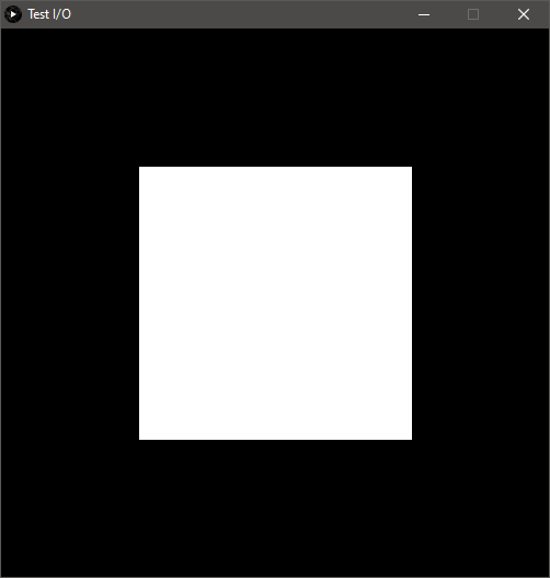
Processing Interface
- Green - at Button Press
- White - at Button Release
- Blue - at recieving '0x01' from the board
- White - at recieving '0x02' from the board
- In the main loop; it checks the Serial data to update the rectangle colors.
- When the mouse is pressed; it makes sure that the mouse location is on the square, changes the square color, and sends a byte value to the board turning its LED ON
- When the mouse is released; it changes the square color back to white, and sends a byte value to turn the LED OFF.
import processing.serial.*;
Serial mySerial;

color value = color(255, 255, 255);
boolean pressed = false;

void setup() {
  surface.setTitle("Test I/O");
  size(500, 500);
  mySerial = new Serial(this, Serial.list()[0], 9600);
}

void draw() {
  background(0);
  if (mySerial.available()>0)
  {
    byte msg = mySerial.readBytes(1)[0];
    if (msg == 0x01) value = color(0, 0, 255);;
    if (msg == 0x02) value = color(255, 255, 255);;
  }
  fill(value);
  rect(125, 125, 250, 250);
}

void mousePressed() {
  if (mouseX>125 && mouseX <375 && mouseY>125 && mouseY<375 )
  {
    pressed = true;
    value = color(0, 255, 0);
    mySerial.write(byte(0x0A));
  }
}

void mouseReleased() {
  if (pressed)
  {
    pressed = false;
    value = color(255, 255, 255);
    mySerial.write(byte(0x0B));
  }
}
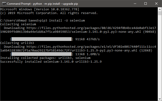
Python Interface
pip install -U selenium
- Import the required libraries
- Creates the driver and action objects
- Launches the website
- Press space every 1.5 seconds, foreverrr
   from selenium import webdriver
   from selenium.webdriver.common.keys import Keys
   from selenium.webdriver.common.action_chains import ActionChains
   import time

   def createWebDriver(browserNumber):
       if   browserNumber == 0: return webdriver.Firefox()		# FireFox
       elif browserNumber == 1: return webdriver.Chrome()		# Chrome

   driver = createWebDriver(1)
   actions = ActionChains(driver)
   driver.get('http://www.trex-game.skipser.com/')

   while True:
       actions.send_keys(Keys.SPACE).perform()
       time.sleep(1.5)
- I had to check the COM port number from the device manager. It was 22. I defined it in line 6
- In line 15, I'm creating the object that i'm going to use for serial
- In line 16 and 17, I'm flushing all the old data accumulated in the buffer, so that the program won't misbehave
- From line 19 to 25, I'm making the program press the space-bar when it recieves the button press byte '0X01'
- It also send the data to make the LED turn ON when the dinosaur starts jumping, and turn OFF when it finishes
from selenium import webdriver
from selenium.webdriver.common.keys import Keys
from selenium.webdriver.common.action_chains import ActionChains
import serial
port = 'COM22'

def createWebDriver(browserNumber):
	if   browserNumber == 0: return webdriver.Firefox()		# FireFox
	elif browserNumber == 1: return webdriver.Chrome()		# Chrome

driver = createWebDriver(1)
actions = ActionChains(driver)
driver.get('http://www.trex-game.skipser.com/')
monitor = serial.Serial(port,9600,timeout=5)
monitor.flush()
monitor.flushInput()
while True:
	data = monitor.read()
	if (data== bytes(b'\x01')):
		monitor.write(bytes(b'\x0A'))
		actions.send_keys(Keys.SPACE).perform()
		monitor.write(bytes(b'\x0B'))
	monitor.flush()
	monitor.flushInput()
Downloads