- Group Assignment:
- Measure the power consumption of an output device
- Individual Assignment
- add an output device to a microcontroller board you've designed,
and program it to do something
- add an output device to a microcontroller board you've designed,
- Link to the group assignment page
- Document how I determined power consumption of an output device with my group
- Document what I learned from interfacing output device(s) to microcontroller and controlling the device(s)
- Describe my design and fabrication process or link to previous examples
- Explaine the programming process/es I used
- Outline problems and how I fixed them
- Include original design files and code
- Include a ‘hero shot/video’ of my board
Roland:MDX-20 FabModules EAGLE Arduino
Group Assignment
Electric power is the rate, per unit time, at which electrical energy is transferred by an electric circuit.
Electric power can't be directly measured, it can be calculated instead. The SI unit of power is the watt which results from multiplying the source voltage by the consumed current.
This means that the power consumption will vary under different source voltages.
In the following videos I'll be measuring the power consumed by different devices.
DC Motor #1
This is a toy DC motor coupled to a gear head.
At around 6V the power seems to consume 0.6 W event at loading the motor.
At around 9V the power seems to consume 1.7 W at loading.
DC Motor #2
This is an electric razor DC motor coupled to an eccentric load to cause vibrations.
At around 5V the power seems to consume 1.5 W.
At around 6V the power seems to consume 2.6 W.
I liked how this motor still moves even when it's supplied with about 0.5 volts.
DC Motor #3
A big motor with gear head.
At around 6V the power seems to consume 2.4 W.
At around 9V the power seems to consume 3.7 W without load, and 18W with a stall load!.
At around 12V the power seems to consume 7 W without load, and 50W with a stall load!.
LiPo Battery Charger
The charger seemed pretty efficient. It only consumed the rated charging current.
Solder Wire
After those many trials, I got curious :D I wanted to know how much heat can a wire of solder endure, since the electrical power consumed is converted to heat through the resistance of materials.
The solder wire seemed to endure up to 14 Watts :D
Understanding DC Motors
A DC Motor can not be derived directly from an MCU for three reasons:
- The power output of an MCU pin is around 0.1W which is not sufficient to drive a motor
- The voltage output of an MCU pin can't exceed 5V
The solution of all of those is using an H-Bridge

An H-bridge is a circuit configuration made with transistor switches controlled by the MCU, which allow the use of external supply voltage, plus the control of direction of that supply voltage.
Fortunately this circuit is embedded into many electric chips, like the A9453 that I'm going to use in this assignment.

Motor PCB Design
Remember how I got bored from designing ATtiny boards? :D In the Input Devices assignment I made a generic layout to make use of that board in this assignment.
Thankfully, the plan is not totally failed :D I can't use the same board, but now I only need to add the H-Bridge chip to the same board design.
I used the same board specs from the Input Devices assignment:
- I would use the internal 8MHz crystal
- would have a voltage regulator, so that I could drive the motor from a battery
- I would keep the ISP header so that I would be able to change the code easily
- I would put an LED so that I can use it for debugging.
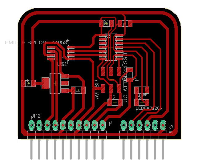
I used eagle to create the PCB. I started with the schematic.
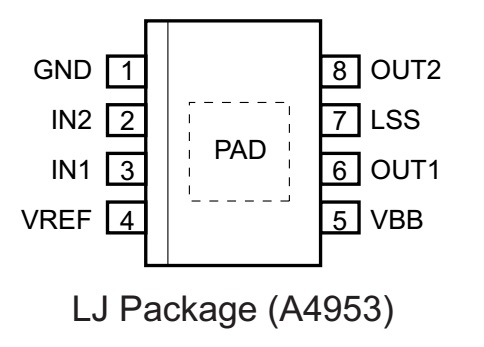
I checked the datasheet for the wiring.

I also made the layout with DRC of 0.45mm distance between traces.
I milled the board using modela MDX-20 like I did in the electronics production week.
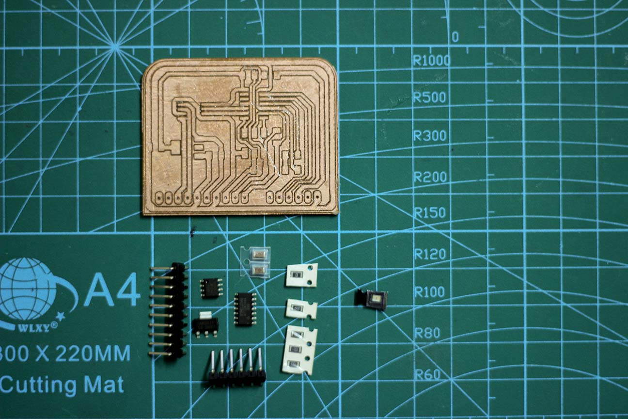
The BOM for the board is:
| Part | Quantity |
|---|---|
| ATTINY44A-SSU-ND IC AVR MCU 4K 10MHZ 8SOIC | 1 |
| RES 499 OHM 1-4W 1% 1206 SMD | 1 |
| RES 10.0K OHM 1-4W 1% 1206 SMD | 3 |
| RES 0.0 OHM 1-4W 1% 1206 SMD | 1 |
| 6 Positions Header Connector 0.100" SMD | 1 |
| SMT RT Angle Male Header 0.1" (36pos) | 1 |
| LED GREEN CLEAR 1206 SMD | 1 |
| CAP CER 1UF 50V X7R 10% 1206 | 2 |
| LM1117 5V Voltage Regulator | 1 |
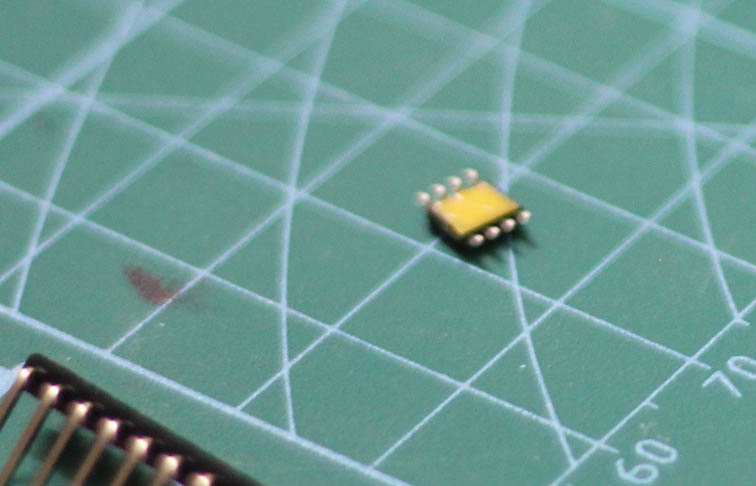
| A4953 Motor Driver 8-SOIC | 1 |
The A4953 chip has a metal pad at the bottom for heat dissipation, but I needed to mill some traces under the chip, so I put some insulation tape on that pad so that it won't make a short circuit with the traces at the bottom.
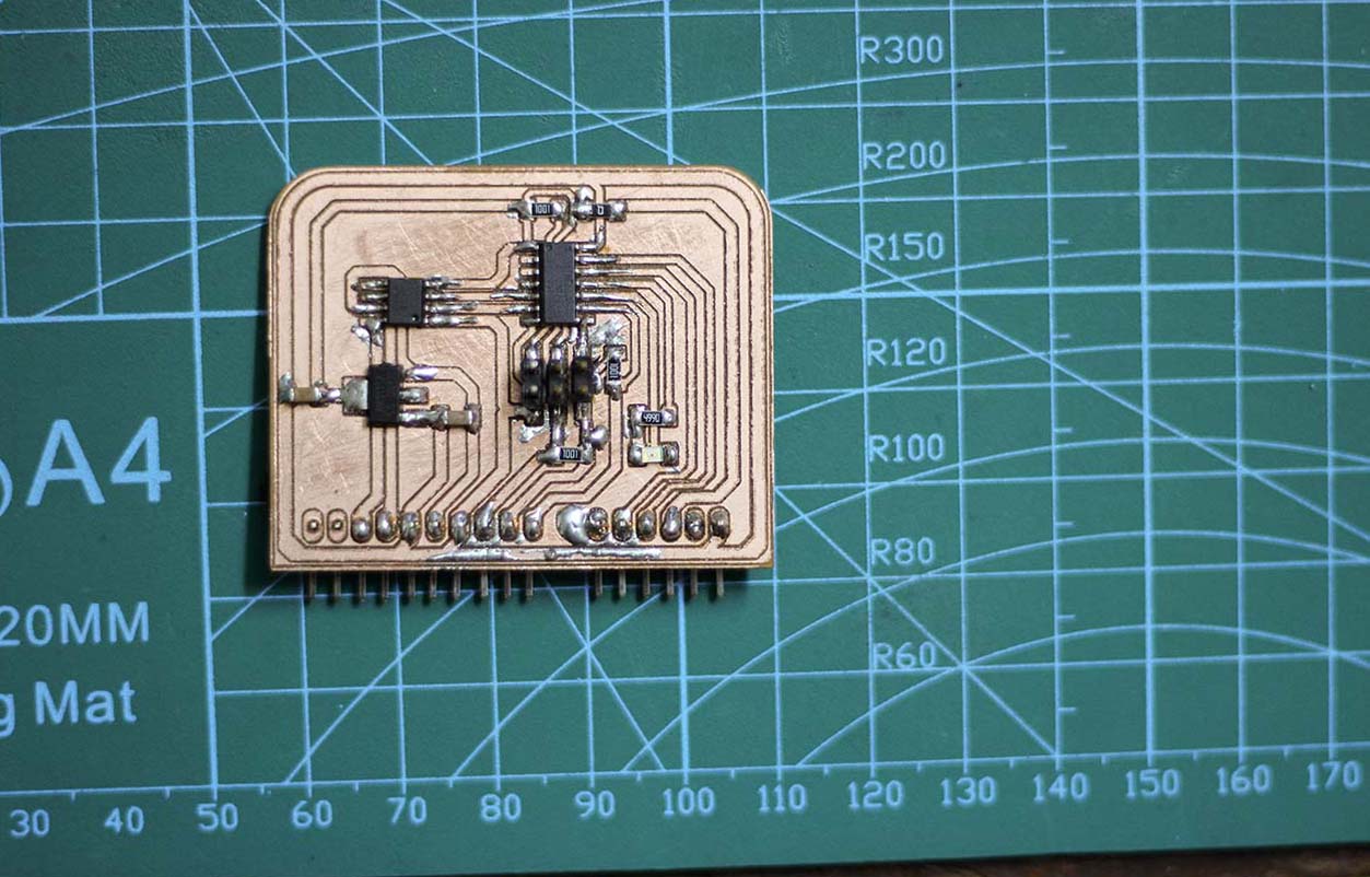
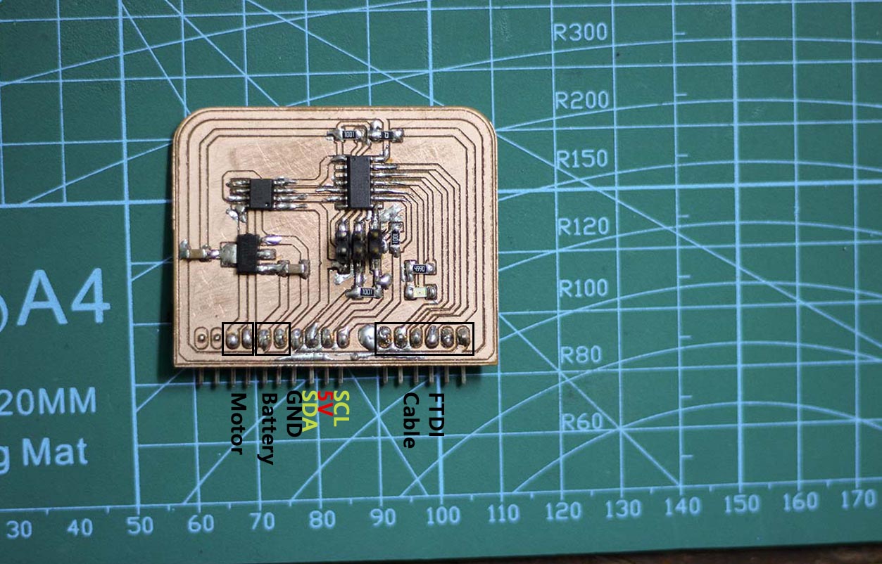
This is after I soldered everything in place.
Motor PCB Testing
The A4953 can be used to drive the motor through using the two inputs pins (IN1 and IN2).
The state of the motor is shown in the following truth table.
| IN1 | IN2 | Description |
|---|---|---|
| N/A | N/A | Motor OFF |
| LOW | LOW | Motor OFF |
| LOW | HIGH | Motor Forwards |
| HIGH | LOW | Motor Backwards |
| HIGH | HIGH | Stop with brakes |
The Arduino code utilizes the truth table to test all those states.
const int ledPin =  2;
const int motorPin1 =  7;
const int motorPin2 =  8;

void setup() {
    pinMode(ledPin, OUTPUT);
    pinMode(motorPin1, OUTPUT);
    pinMode(motorPin2, OUTPUT);
}

void loop() {
    // Drive the motor in a direction
    digitalWrite(ledPin, HIGH);
    digitalWrite(motorPin1, HIGH);
    digitalWrite(motorPin2, LOW);
    delay(1000);
    // Stop the motor
    digitalWrite(ledPin, LOW);
    digitalWrite(motorPin1, LOW);
    digitalWrite(motorPin2, LOW);
    delay(500);
    // Drive the motor in the opposite direction
    digitalWrite(ledPin, HIGH);
    digitalWrite(motorPin1, LOW);
    digitalWrite(motorPin2, HIGH);
    delay(1000);
    // Stop the motor
    digitalWrite(ledPin, LOW);
    digitalWrite(motorPin1, LOW);
    digitalWrite(motorPin2, LOW);
    delay(500);
}
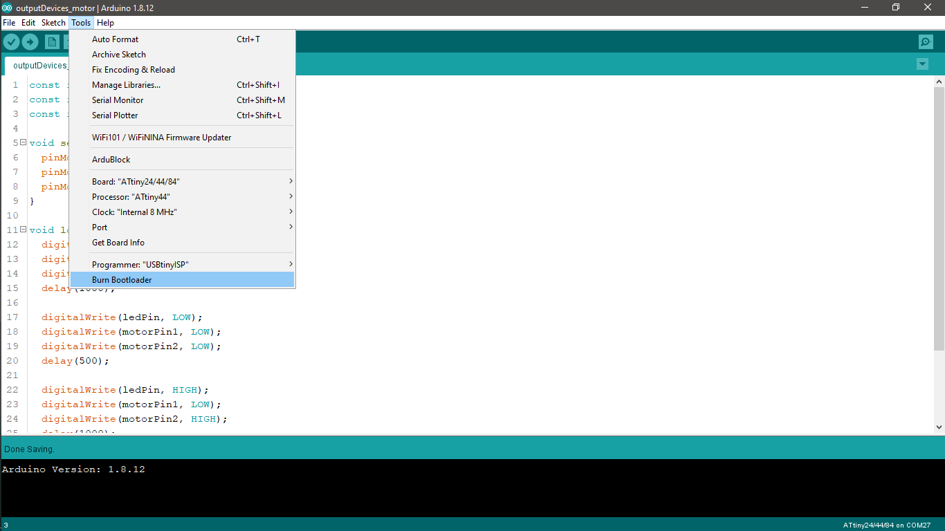
I burned the bootloader on the MCU to set the fused to work with the internal resistor. I then uploaded the code like I did in the electronic production week.


Here's a video demo for the results:
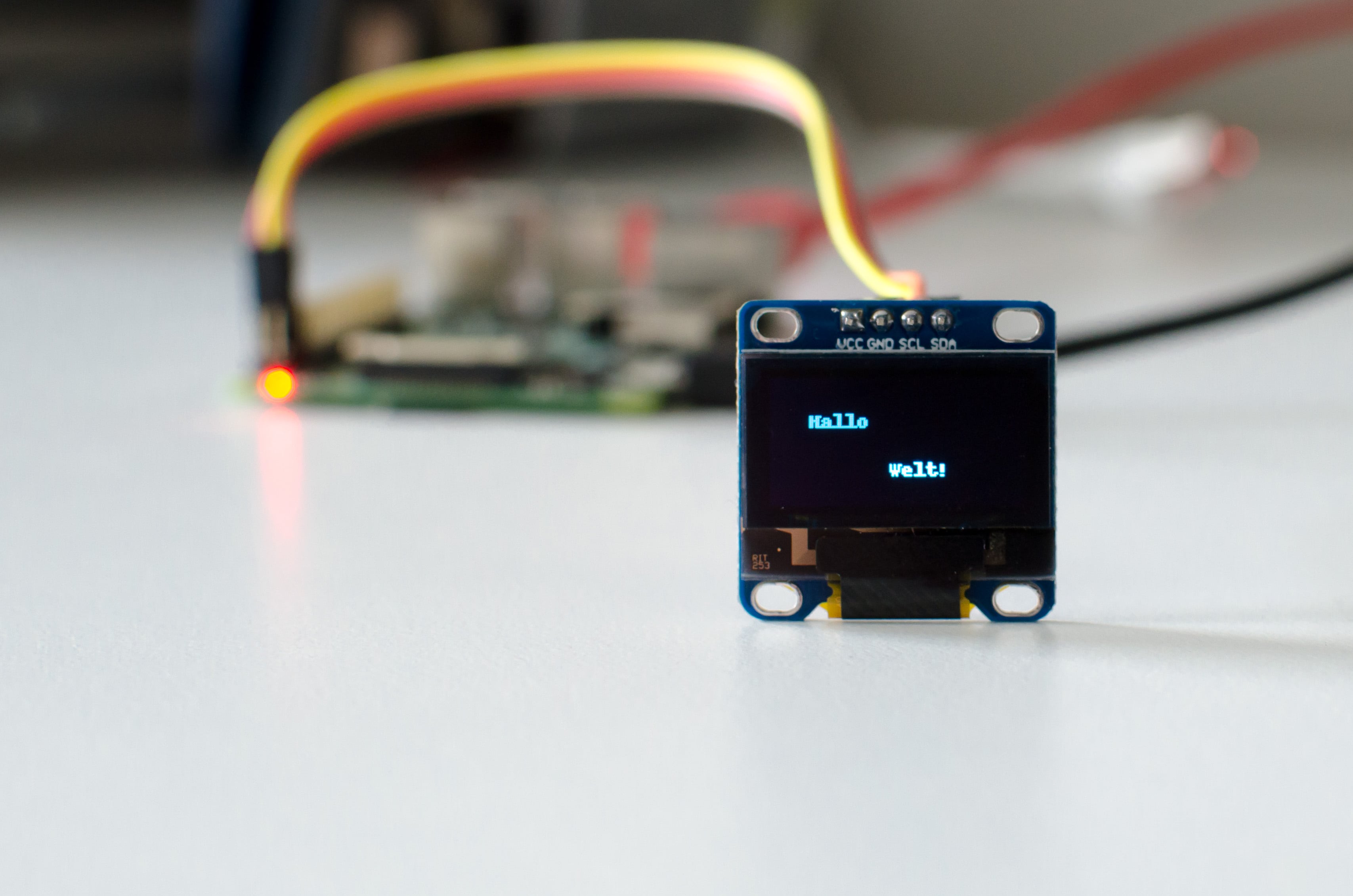
Image to OLED
Before getting the access to the lab to make the PCB I used Arduino uno with an OLED and tried to display custom messages on the OLED with an easy way.
The idea was to use a simple website called dot2pic.com to generate the hex code for each pixel in order to decide whether it should be turned ON of OFF.


The custom code is put into a byte array which is executed with the function
bytes_to_image()

Here's a video demo for the process.