- Group Assignment:
- Use the test equipment in your lab to observe the operation of a microcontroller circuit board
- Individual Assignment:
- redraw an echo hello-world board,
- add (at least) a button and LED (with current-limiting resistor)
- check the design rules, make it, and test it
- extra credit: simulate its operation
- Link to the group assignment page
- Document what I have learned in electronics design
- Explaine problems and how I fixed them
- Include original design files (Eagle, KiCad, - whatever)
- Include a ‘hero shot’ of my board
- Load a program and test if my board works

Roland:MDX-20 FabModules EAGLE Photoshop Arduino
Group Assignment
This is the GW Instek GDS-820C oscilloscpe.
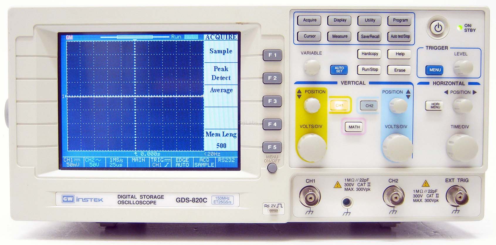
The main purpose of an oscilloscope is to graph an electrical signal as it varies over time. I'll be using this device to observe the operation of a microcontroller circuit board I designed in this assignment.
Features:
- 150MHz Bandwidth
- Color LCD Display
- 125k Long Memory
- 8 x 10 Division Display
- 2 Channels
- Input Impedance 1MΩ ±2Ω, ~22pF
- Sensitivity 2mV/div to 5V/div
- 25Gsa/s Sampling Rate for Repetitive Waveforms
- Auto Setup Sequence
Now, let us talk about the so many control buttons in this device.
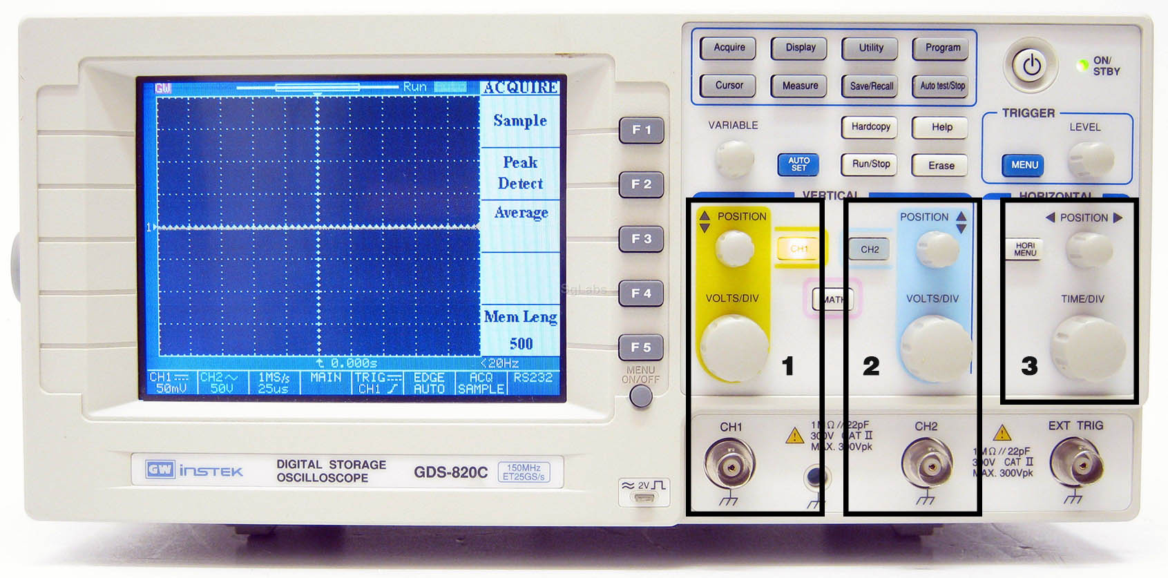
- The first group is the controls for the changing the voltage per division and the position of channel 1 signal
- It does the same control but for channel 2. Note that the two channels can be displayed at the same time
- The third group of controls changes the time per division for both channel 1 and channel 2
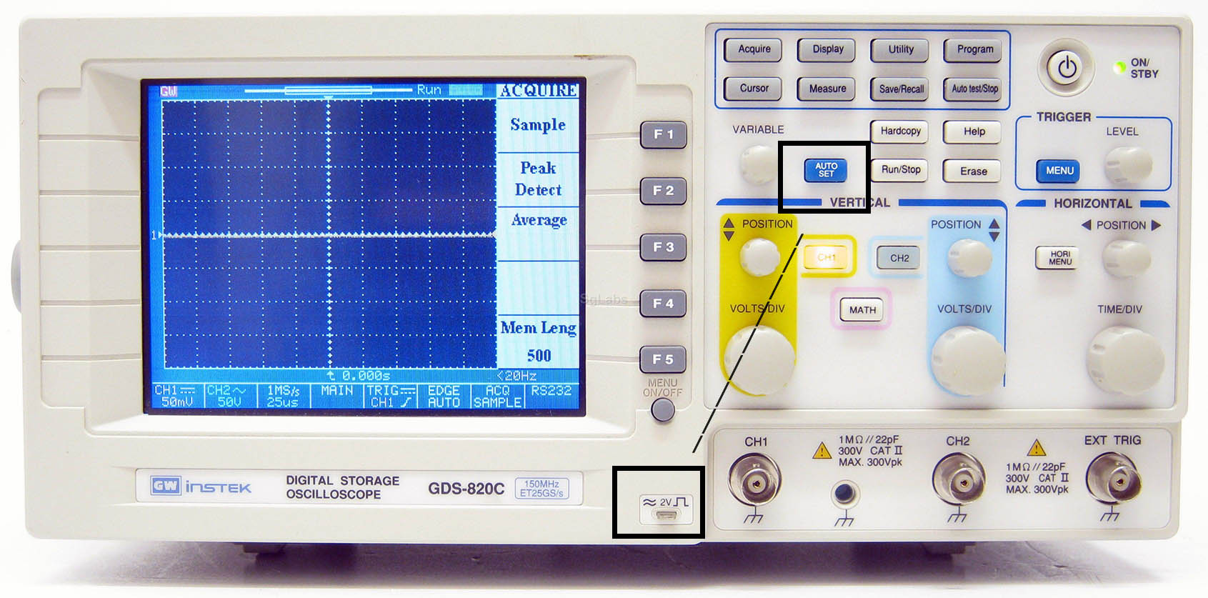
If you are confused about using the oscilloscope, you can calibrate the display by hocking one of the channels to the calibration pin and pressing the auto set button.
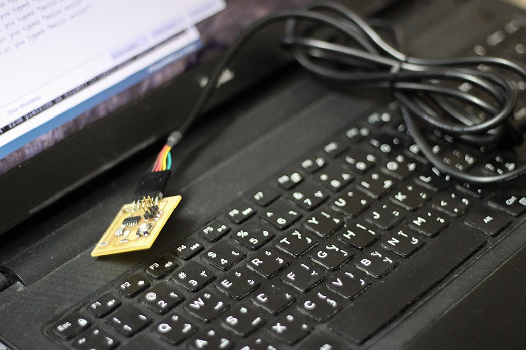
The oscilloscope probe has two wires: one for the signal, and the other for the reference (usually the circuit ground)
I hocked the reference to the GND pin of the FTDI, and signal wire to the TX pin.
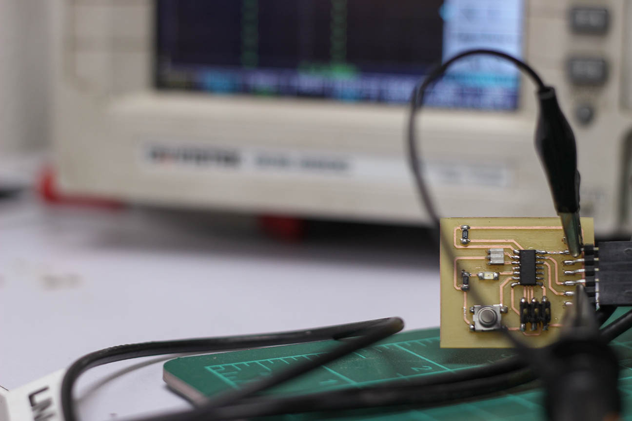
The oscilloscope had a lag that couldn't show the UART signals.
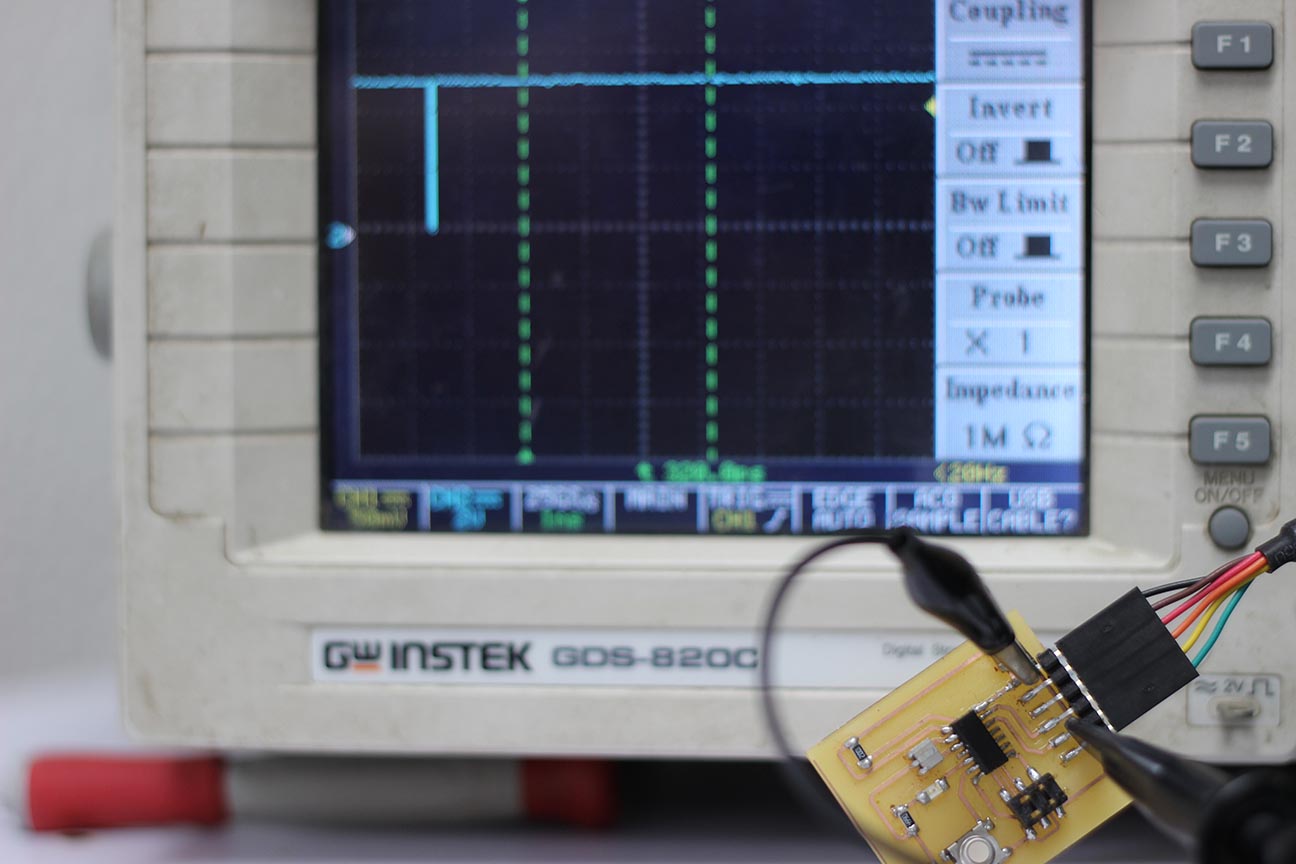
I programmed the board to blink the LED each 250ms and tested the signal that is going to the LED.
The oscilloscope signal seemed to have a lag like before, but the continuous signal gave it the time to view the signal.
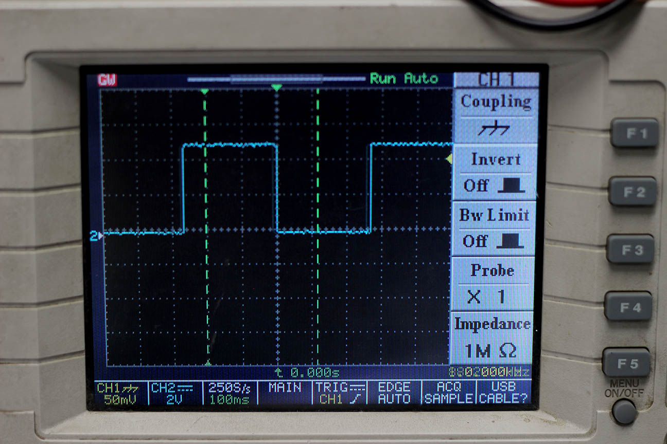
Each vertical space represents 2v, and each horizontal space represents 100ms.
- The count of the vertical squares is about 2.5 squares.
Then the high signal equals 2 * 2.5 = 5V - The count of the horizontal squares is about 2.5 squares.
Then the high signal equals 100 * 2.5 = 250ms
This is exactly like what I programmed the MCU to do.
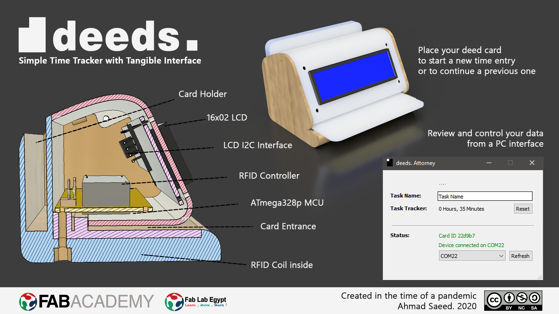
Circuit Design
I have experience in electronics, but I had to understand specifically what to do before moving on and going through the design process. I broke down the original board into components and found out it's a bare-minimum setup for the ATTiny44A MCU with ISP and FTDI interface. It contained:
|
|
Making drafts is always a good way to start getting things done
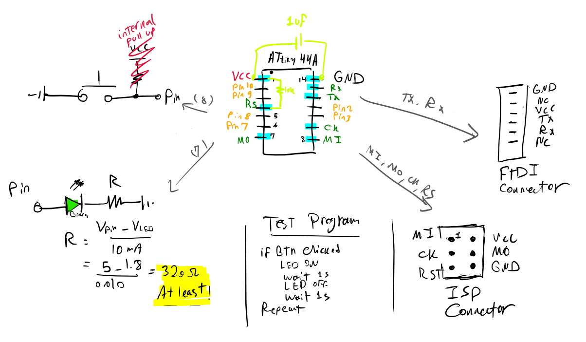
I also have old experience with EAGLE; but I only worked with THT components and didn't have the chance to try SMD. Luckily, I managed to do the SMD electronics design with minimal errors. I got “inspired” from the ready PCB layout and didn't spend time re-planning the layout. I just made a similar PCB and added a button, and an LED with the current-limiting resistor.
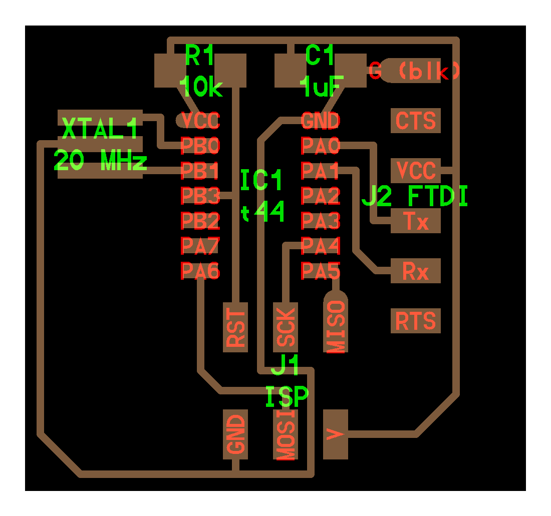
I first made the schematic wiring according to the previous drafts, then started drawing the layout using 16 mil trace width.


When I finished connecting and moving things around; I ran the DRC check for clearance errors. The smallest end-mill we have is about 0.4mm diameter. Putting that into the DRC settings; I found some clearance errors between the traces running under the ATTiny.

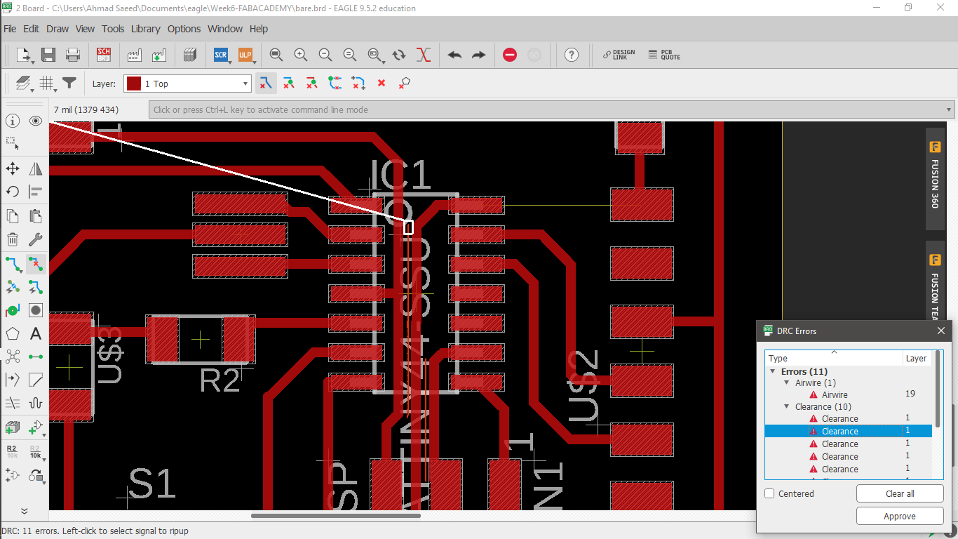
I had to replace those traces with smaller width: 14 mil, and it worked. The DRC check finally is giving no errors.
Circuit Production
Before going into this, I have to admit that the small traces running under the ATTiny and through the ISP were my biggest fears. In Fab Lab Egypt we have the Roland MDX-20 with a set of 1/64 and 1/32 end mills, and FR1 copper sheets.

I loaded my design into the Fab Modules, adjusted the origin, and calculated the toolpath. I was reliefed when I saw the toolpath coming correctly between the traces, and got the courage to run the process. I set the number of offsets to be -1 in order to get a clean board. It took around 20 minutes to finish.


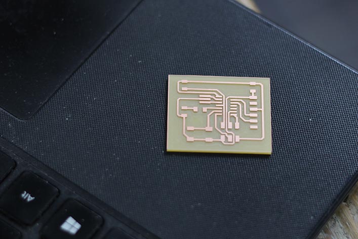
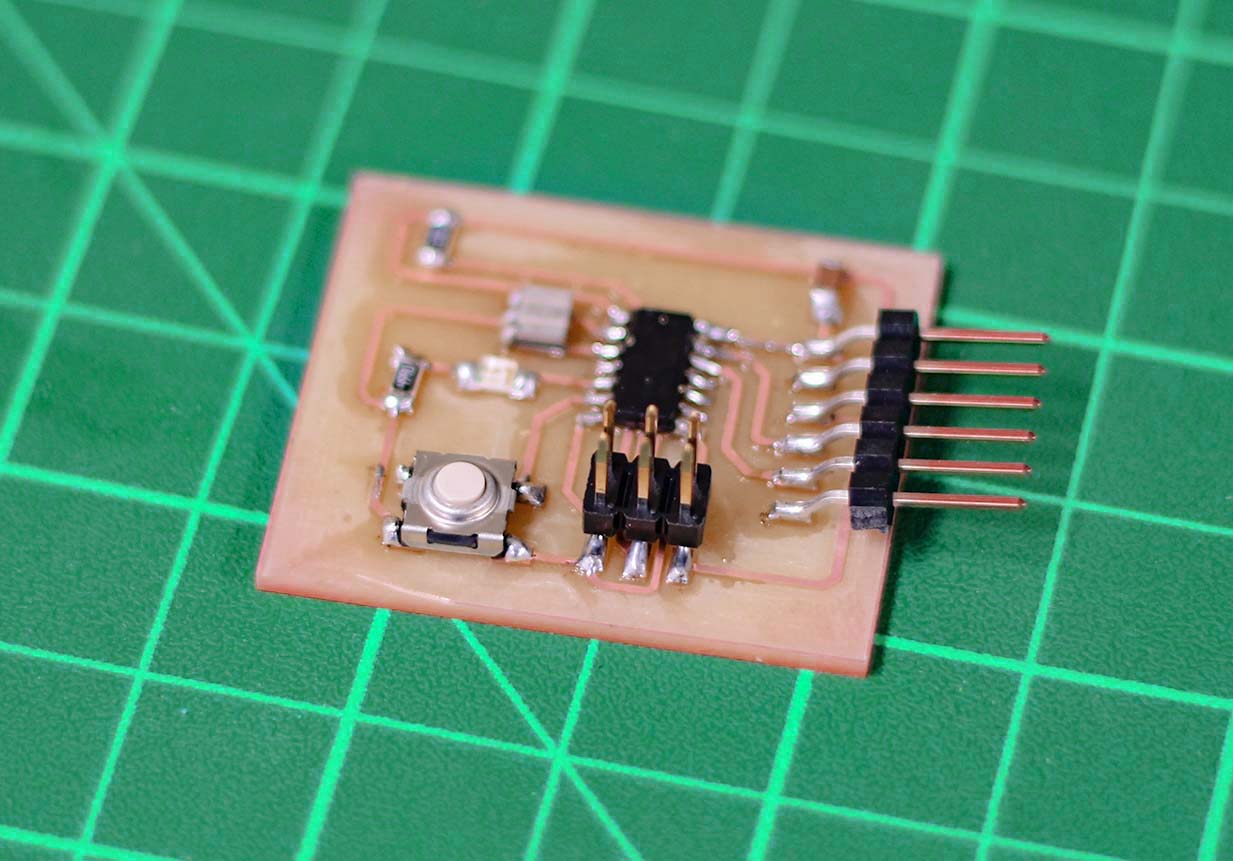
Welcome to your life, baby PCB :"D
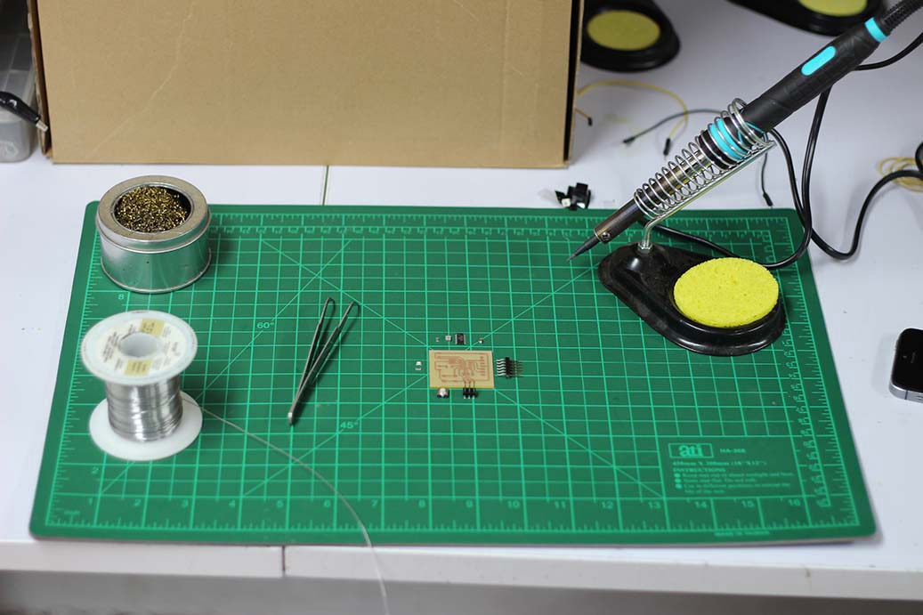
Soldering
Here comes the most amusing part for me; getting components out of the inventory, and placing everything on the table for shooting the setup. Here is my Bill of Materials:
| Part Number | Description | Quantity |
|---|---|---|
| ATTINY44A-SSU-ND | IC AVR MCU 4K 10MHZ 8SOIC- | 1 |
| XC1109CT-ND | CER RESONATOR 20.00MHZ SMD | 1 |
| 609-5161-1-ND | 6 Positions Header Connector 0.100" SMD | 1 |
| S1143E-36-ND | SMT RT Angle Male Header 0.1" (36pos) | 1 |
| 445-1423-1-ND | CAP CER 1UF 50V X7R 10% 1206- | 1 |
| 311-10.0KFRCT-ND | RES 10.0K OHM 1-4W 1% 1206 SMD | 1 |
| 311-499FRCT-ND | RES 499 OHM 1-4W 1% 1206 SMD | 1 |
| B3SN-3112P | SWITCH TACTILE SPST-NO 0.05A 24V | 1 |
| 160-1169-1-ND | LED GREEN CLEAR 1206 SMD- | 1 |
Now comes the hardest part: soldering the components using my bulky hands. I ran some flux over the board and used a fine-tip soldering iron. I got somehow used to handling the small SMD parts, eventually.

After a 30-minute struggle, I finally got my board nice and clean ^_^

echo hello-world
Three things to do:
- Compile the code into hex file
- Update the ATTiny fuses and hex file
- Test
Compiling the code
I'll be using Arduino IDE to compile the code for the ATTiny44A
- Download the ATTiny library from the high-low tech group of MIT
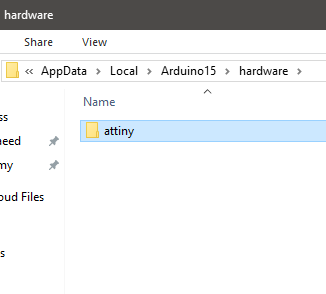
- Add the library to a subfolder called “hardware” in your Arduino sketchbook folder (you can find its location in the preferences dialog under “File” -> “Preferences”)
- You should end up with a folder structure like this: “Arduino” > “hardware” > “attiny”. The “attiny” folder should contain a file “boards.txt” and another folder called “variants”
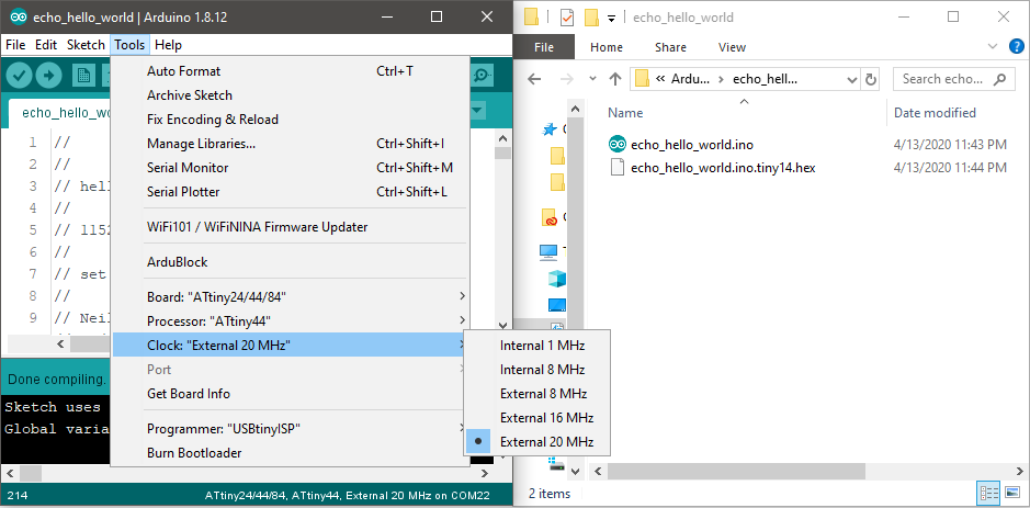
- Restart the Arduino development environment
- You should see a several ATTiny entries in the menu under “Tools” > “Board” menu like in the image below.
- I copied the contents of the code file into an Arduino Sketch
- I exported the hex file by selecting Export compiled Binary from Sketch menu
Burn Fuses and Hex file into the ATTiny
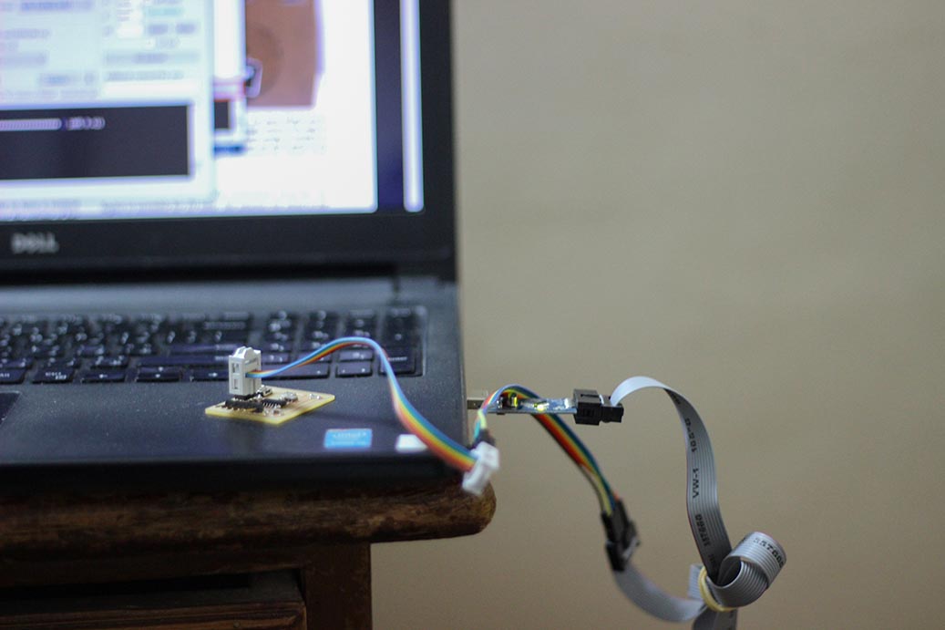
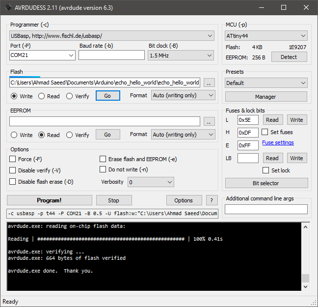
I needed to set lfuse to 0x5E for 20 MHz xtal. I used USBasp programmer along side with AVRDUDESS , which is a GUI for AVRDUDE, to set the fuses. It was done really easily
Testing the echo
I used an FTDI cable to convert from USB to TTL.
I opened Arduino Serial Monitor to do the test.

Downloads