- Group Assignment:
- Test the design rules for your 3D printer(s)
- Individual Assignment:
- Design and 3D print an object (small, few cm3, limited by printer time)
that could not be made subtractively - 3D scan an object (and optionally print it)
- Design and 3D print an object (small, few cm3, limited by printer time)
- Link to the group assignment page
- Explain what I learned from testing the 3D printers
- Document how I designed and made my object and explain why it could not be easily made subtractively
- Document how I scanned and prepared an object (for 3D printing)
- Include my original design files for 3D printing (both CAD and common format for 3D printing)
- Include my hero shots


Fusion360 PrusaSlicer Prusa i3 MK3 Canon 600D ReCap Meshmixer
Group Assignment
This is Fab Lab Egypt's PRUSA i3 MK3 3D Printer.
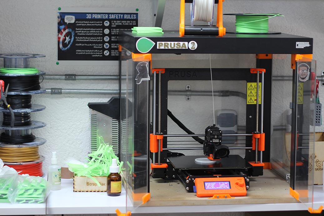
Technical Specs
- Build volume: 25 x 21 x 21 cm
- Layer height: 0.05 – 0.35 mm
- Nozzle Diameter: 0.4mm
- Max hotend/heatbed temp.: 300 °C / 120 °C
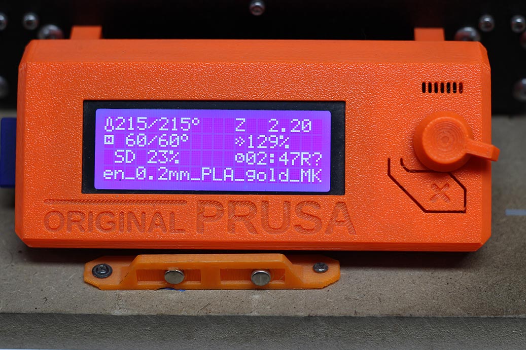
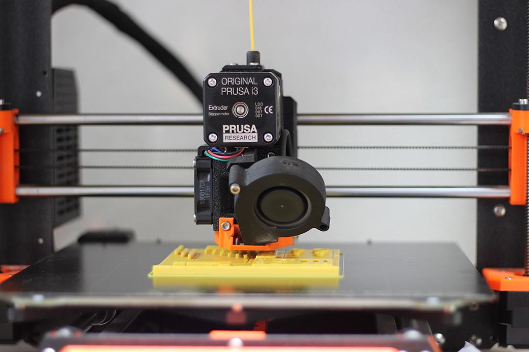
Printing the Test File.
I've decided to use this file from Thingiverse.com. The file was sliced on PrusaSlicer , then copied on the printer memory card, and finally selected to be printed.
Printer Design Rules
We've tested the following settings on Plywood sheets:
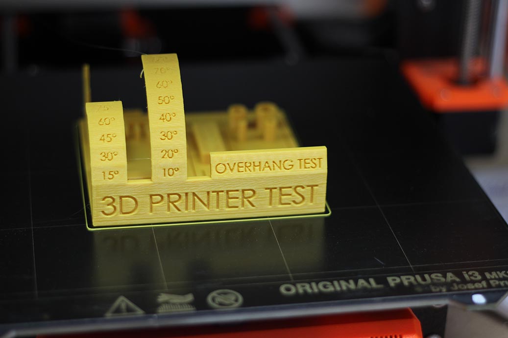
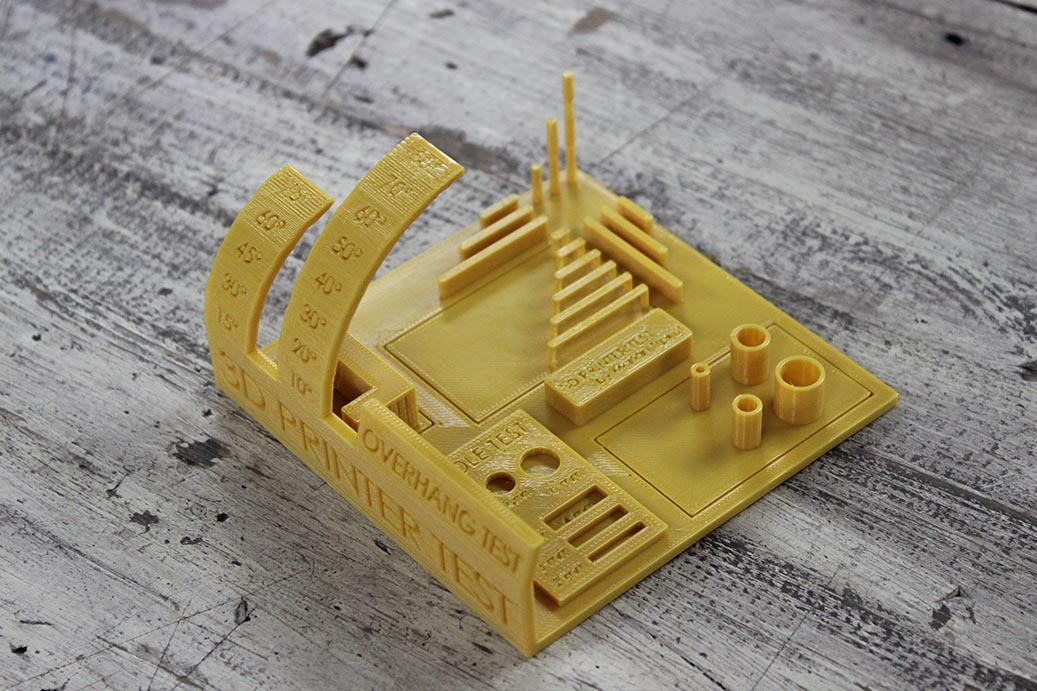
| Parameter | Value |
|---|---|
| Average Tolerance | 0.5mm |
| Max Horizontal Bridge | 30mm |
| Max Overhangs | 45° |
Design for 3D Printing
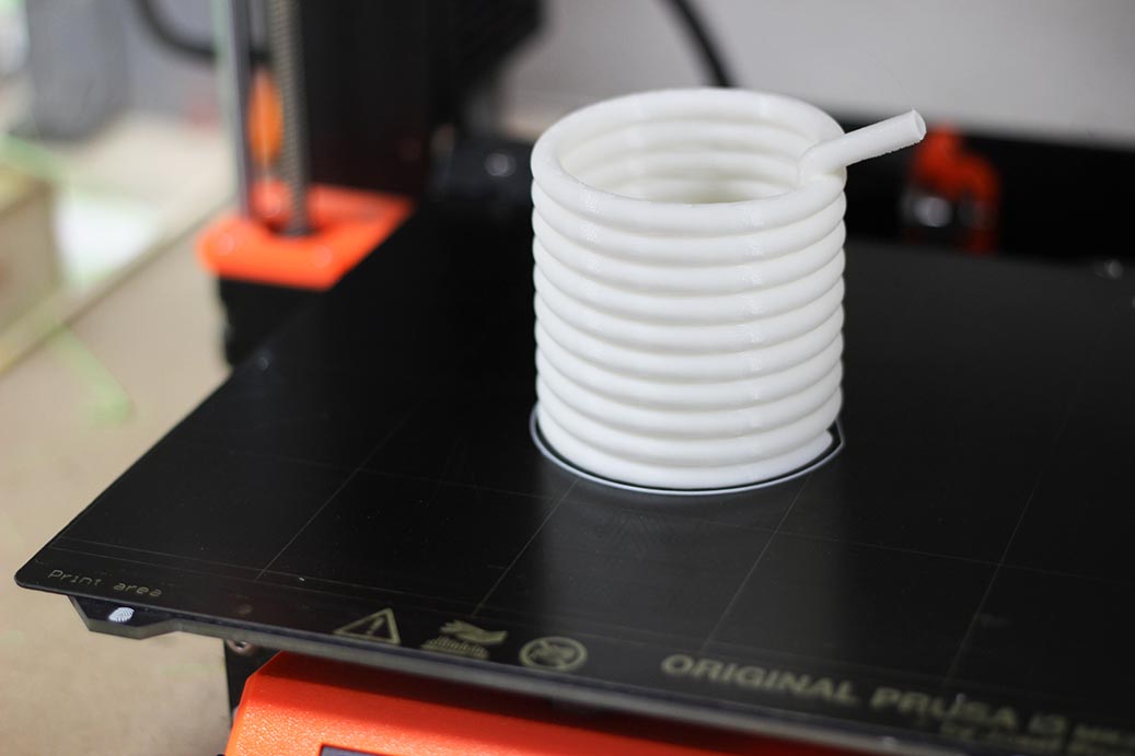
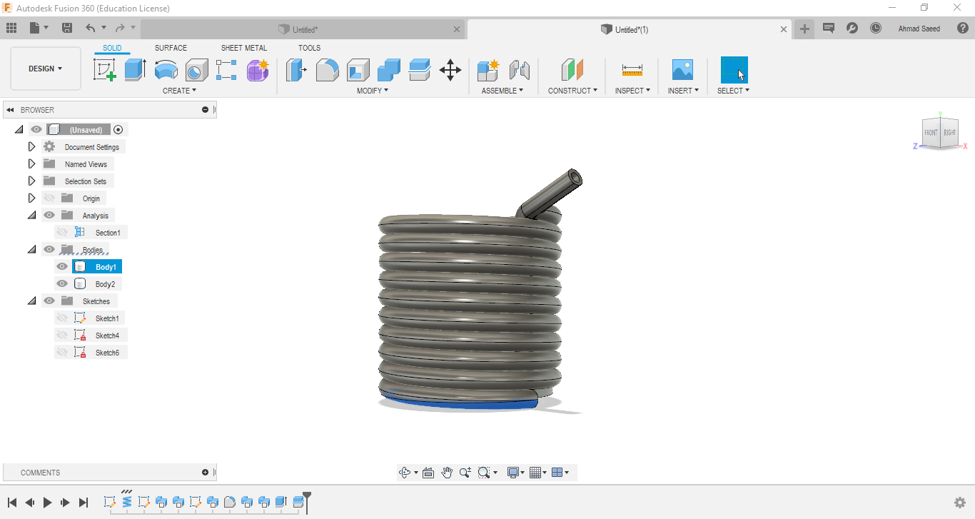
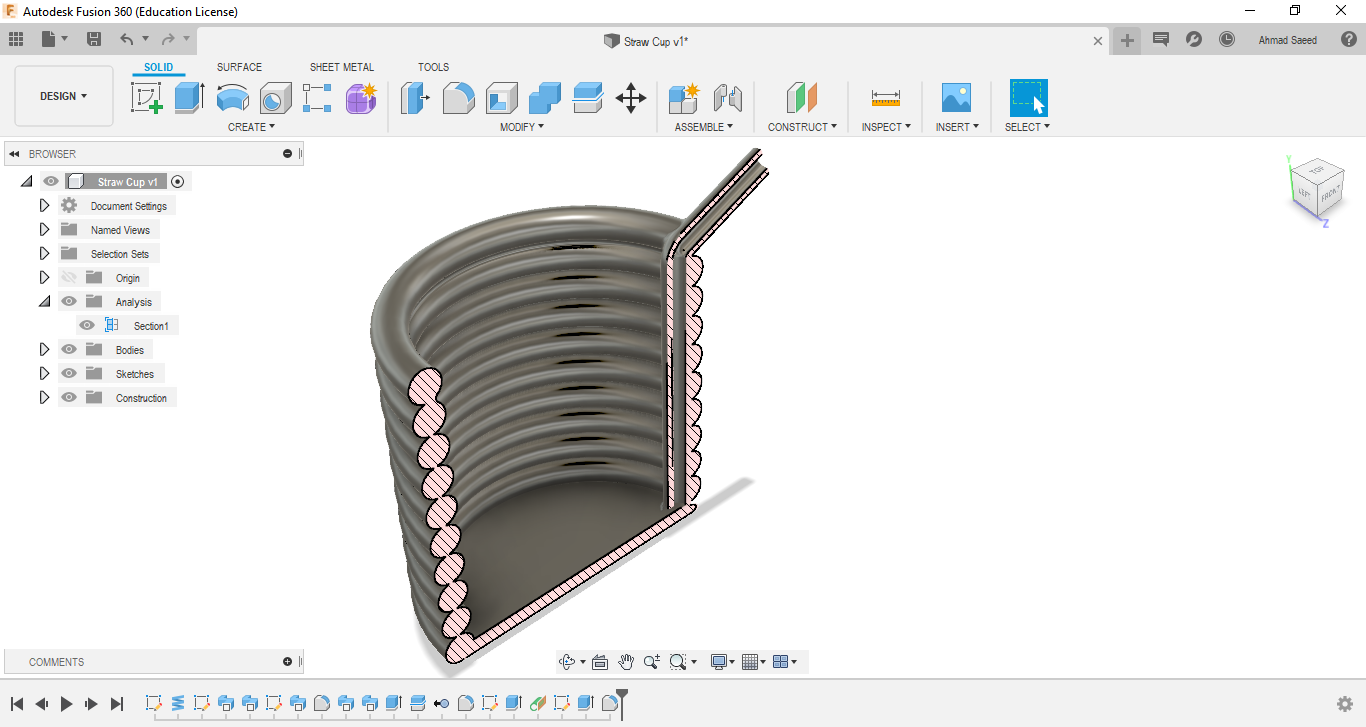
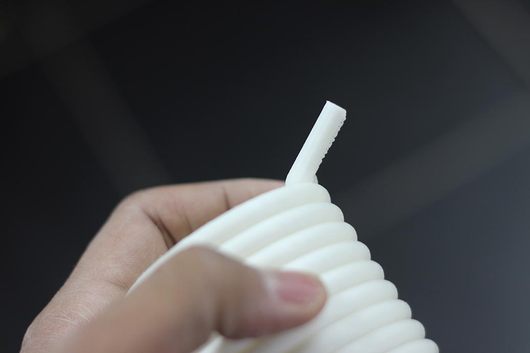
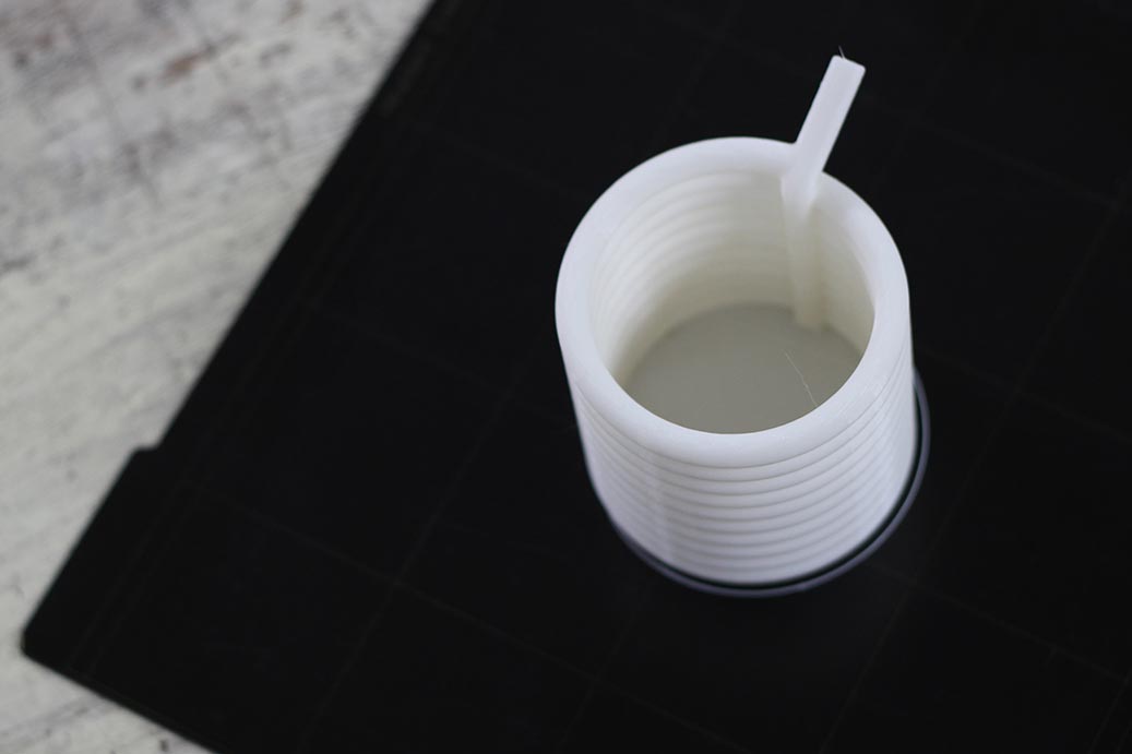
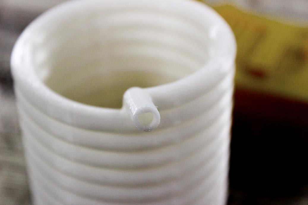
The task was to design something that could not be made subtractively. This basically means that it should have holes or kind of structure that can't be reached with an endmill. I did some search and found this thingiverse part, which is a straw-like cup, with a real straw printed inside.
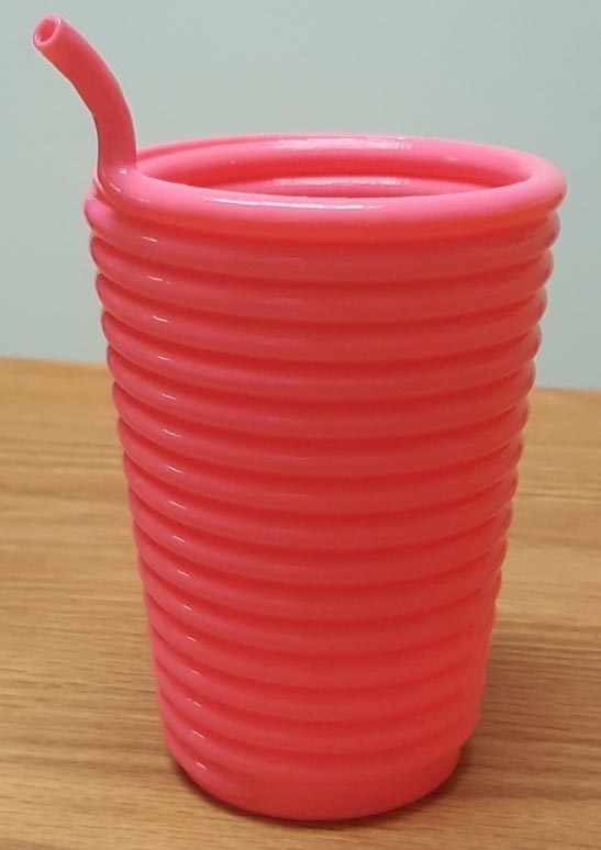
The fixed straw surely can't be manufactured subtractively; because of the long-curved hole inside.
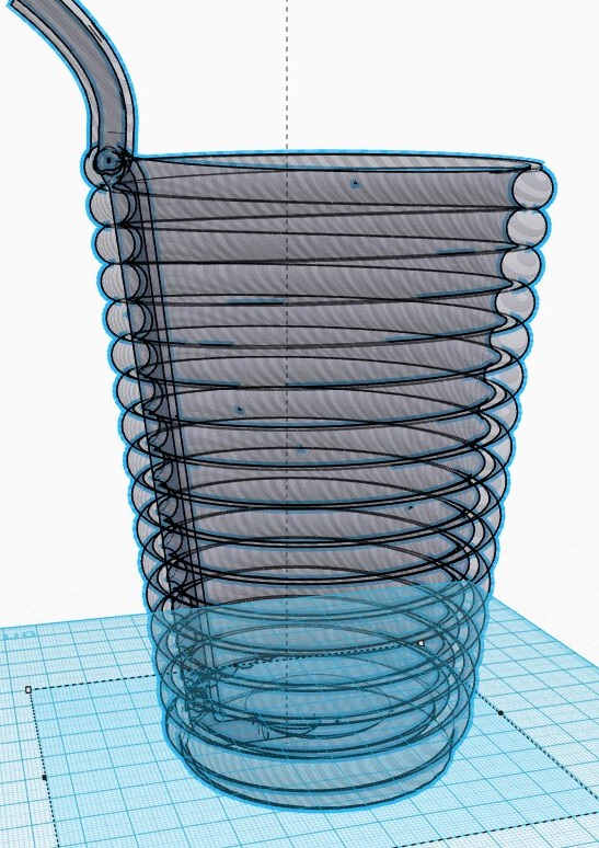
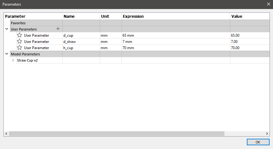
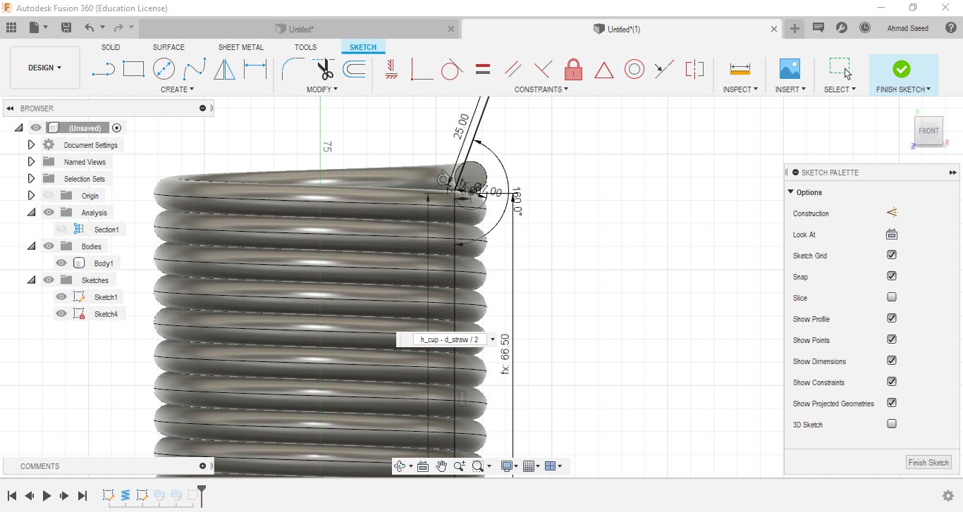
Previously, I fell in love with using design parameters :D I started the work by setting some parameters and drawing a basic circle for the cup using those parameters.
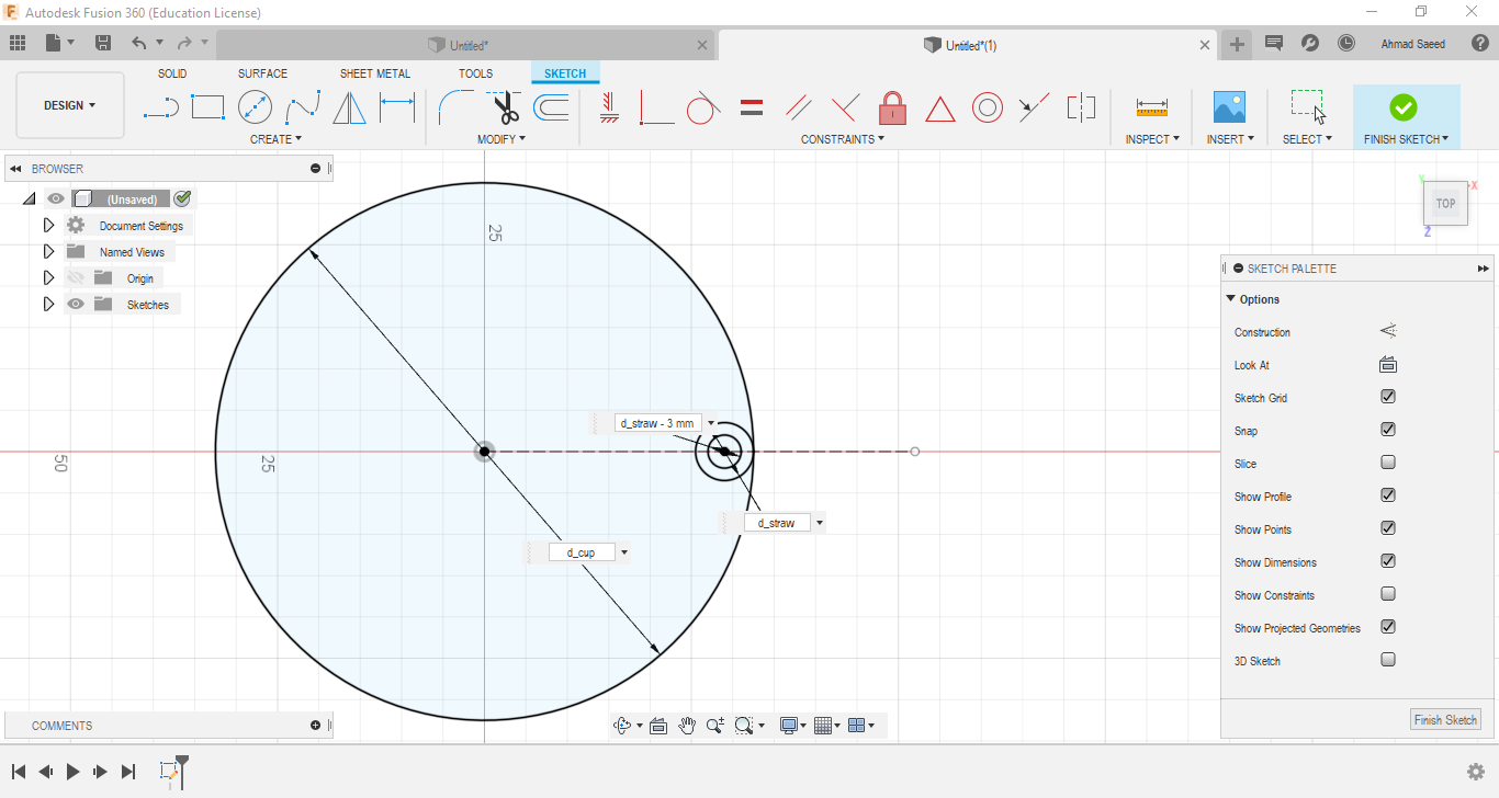
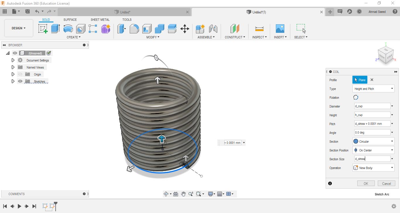
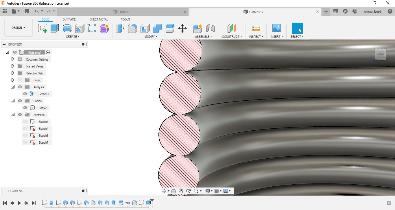
I then made a Coil and made set it's parameters to make no gaps between the coil turns. Fusion360 refused to make a zero gap between the turns, so I made the gap very small. Notice the 0.0001mm added to the Pitch diameter of the coil turns.
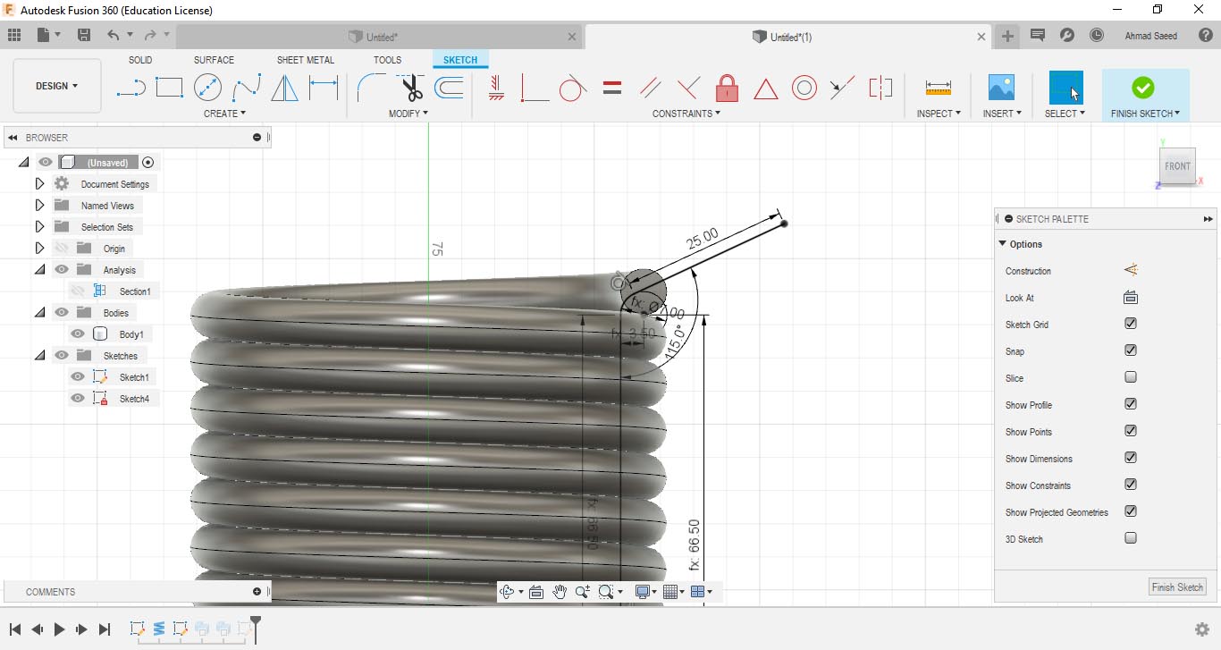
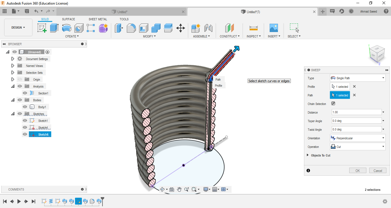
I then constructed a mid-plane inside the cup, then drew a line where the straw should. The plan was to sweep a small circle with a hole inside; along that line.
The plan didn't go really well as planned. Fusion made a strange glitch whenever I tried to sweep the circle along the line. I tried to re-launch the program, but no hope.
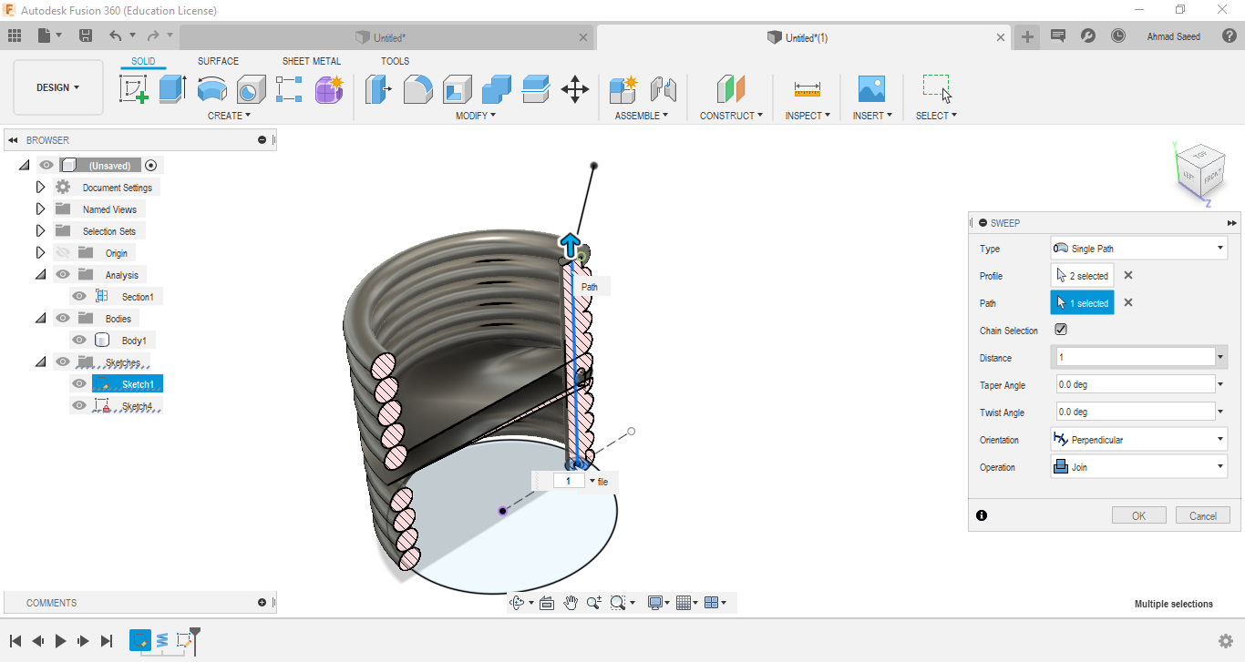
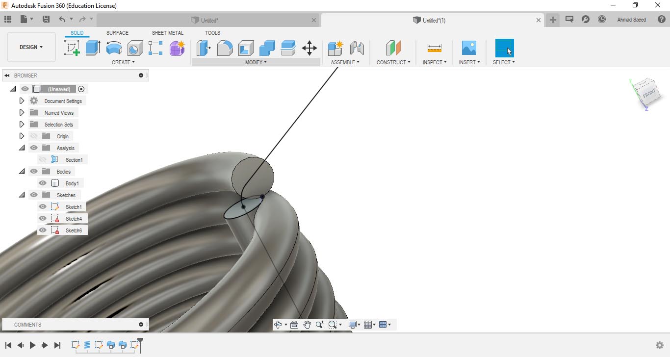
I managed to solve the problem by sweeping the circle to half the path, then sweeping again to the full length. The problem was partially solved, but the sweeping path couldn't be fully selected.
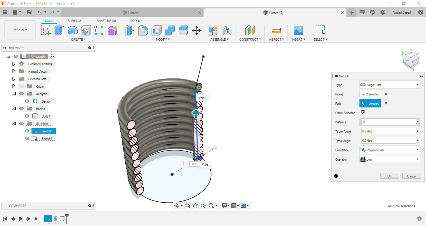
I tried to edit the slope of the sweeping path curve, but it didn't work either.
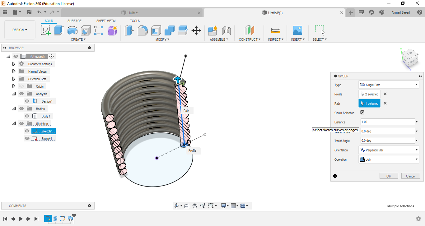
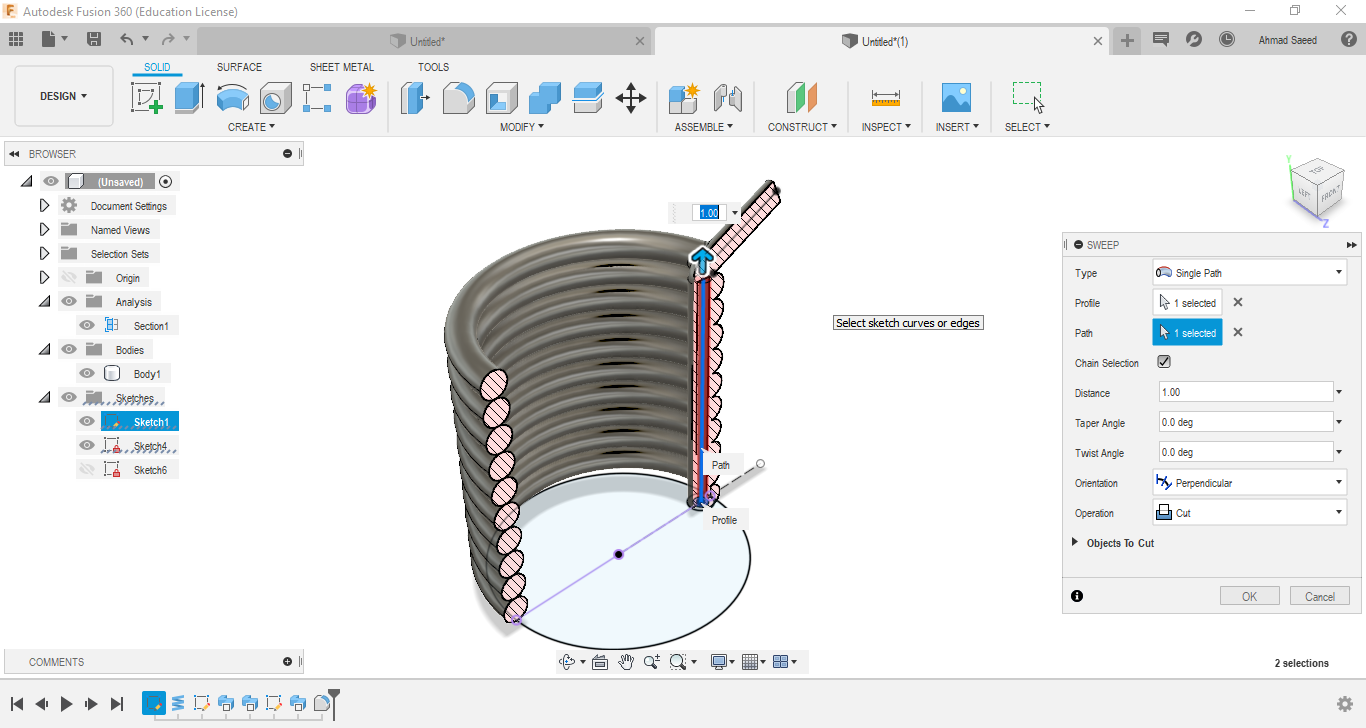
I drew another circle at the end of the swept circle part, then made another sweeping along the rest of the curve. This finally worked!

I repeated the last process with a smaller circuit but sweeping a cut this time to make the straw hollow.
The hard part seemed to be nicely done. The only missing thing was the bottom cup base and some refinements.

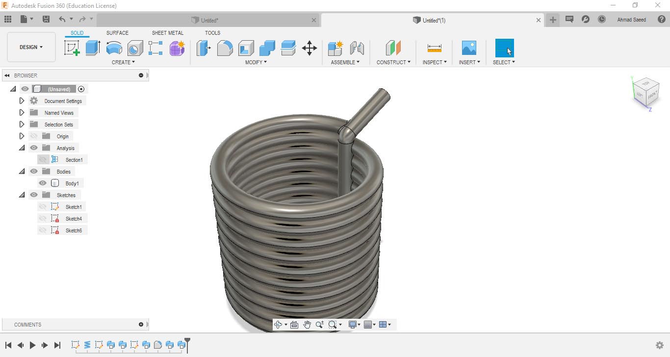
I added the cup base, then cut the base flat- removing a part of the coil.
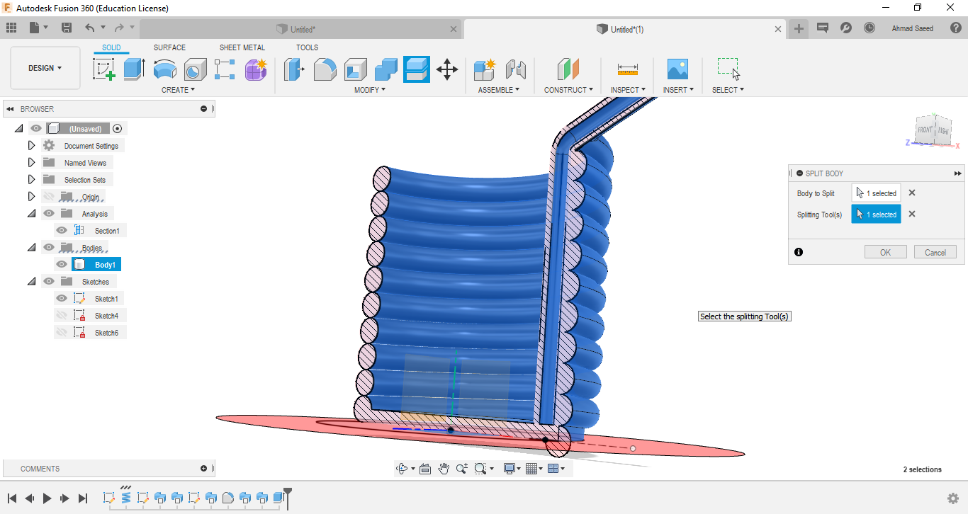
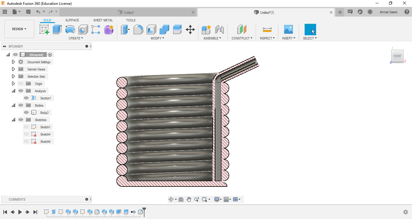
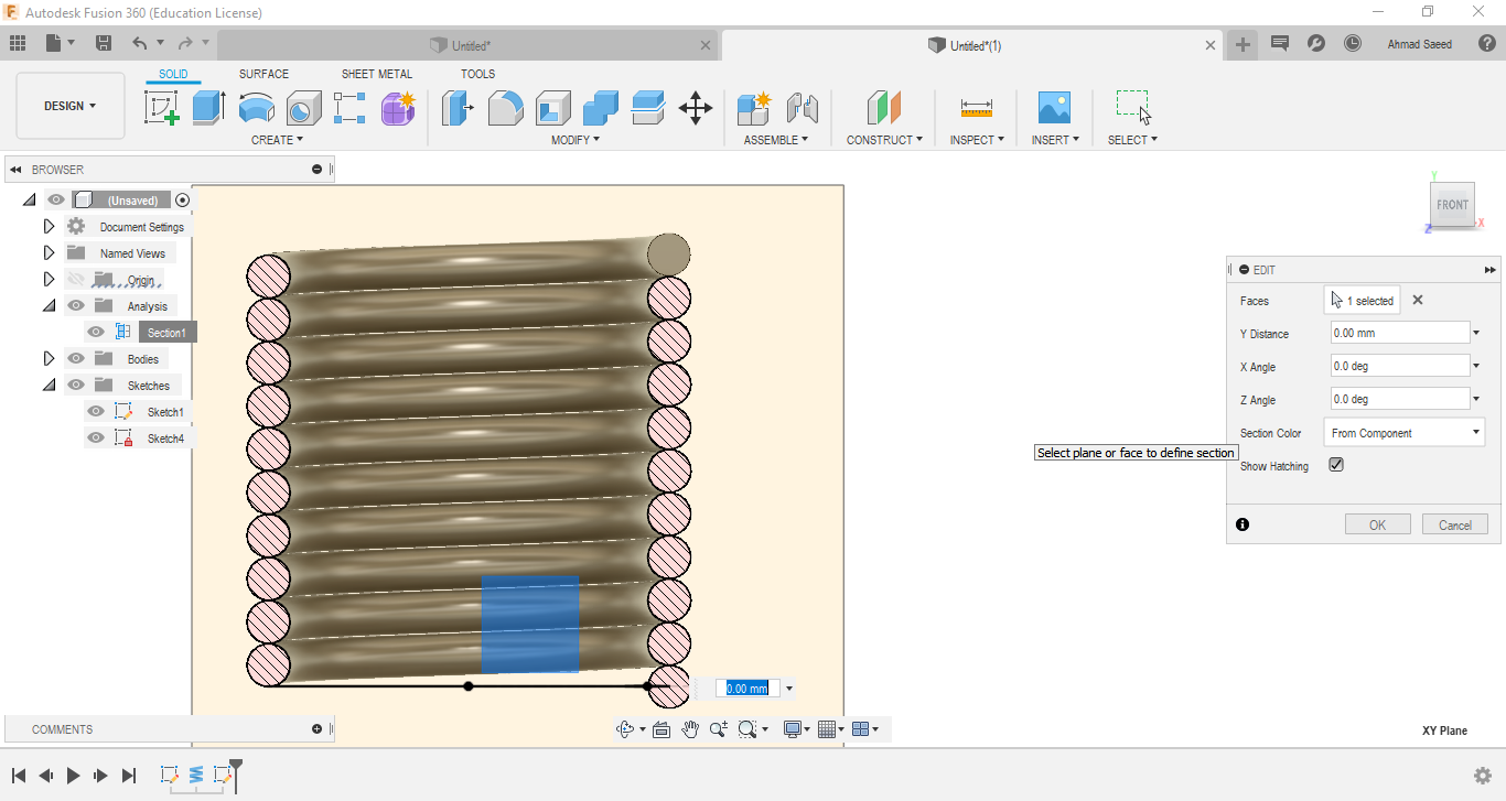
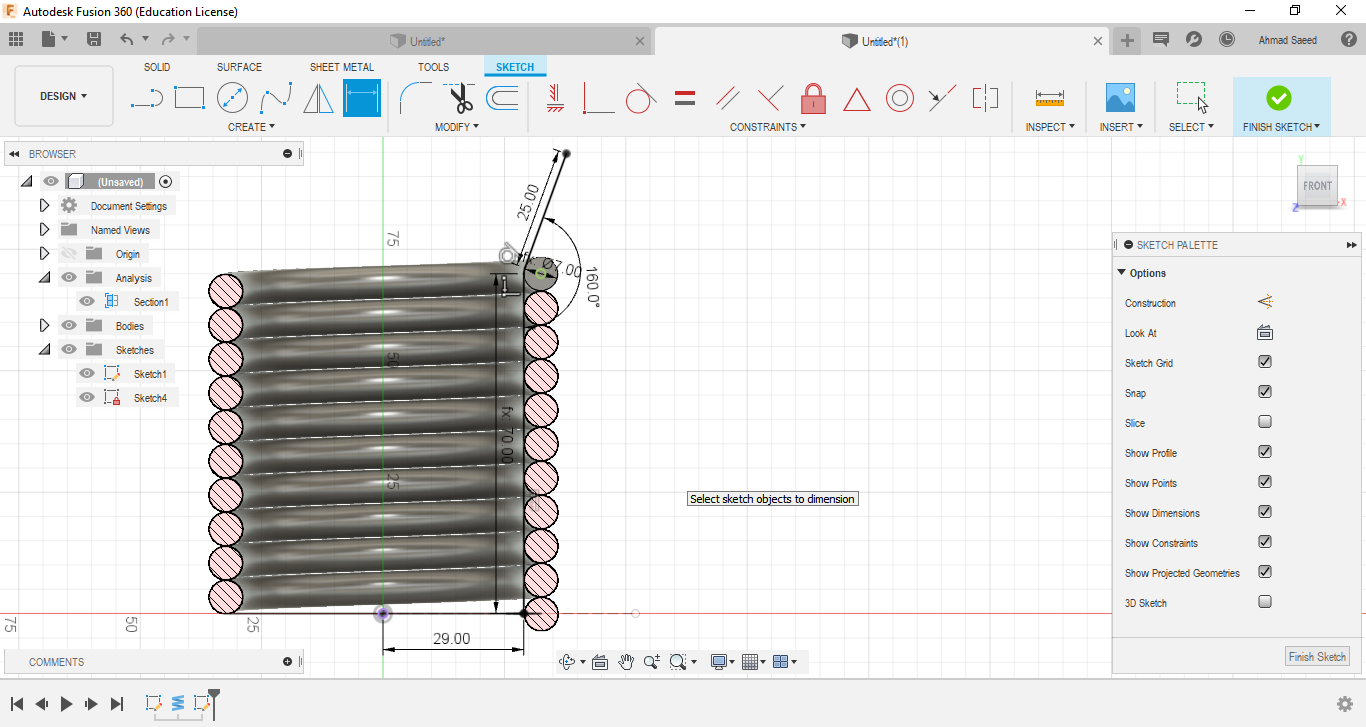
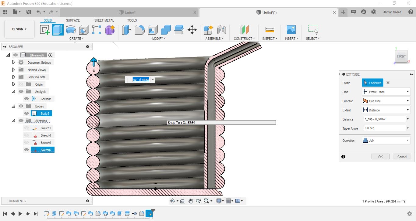
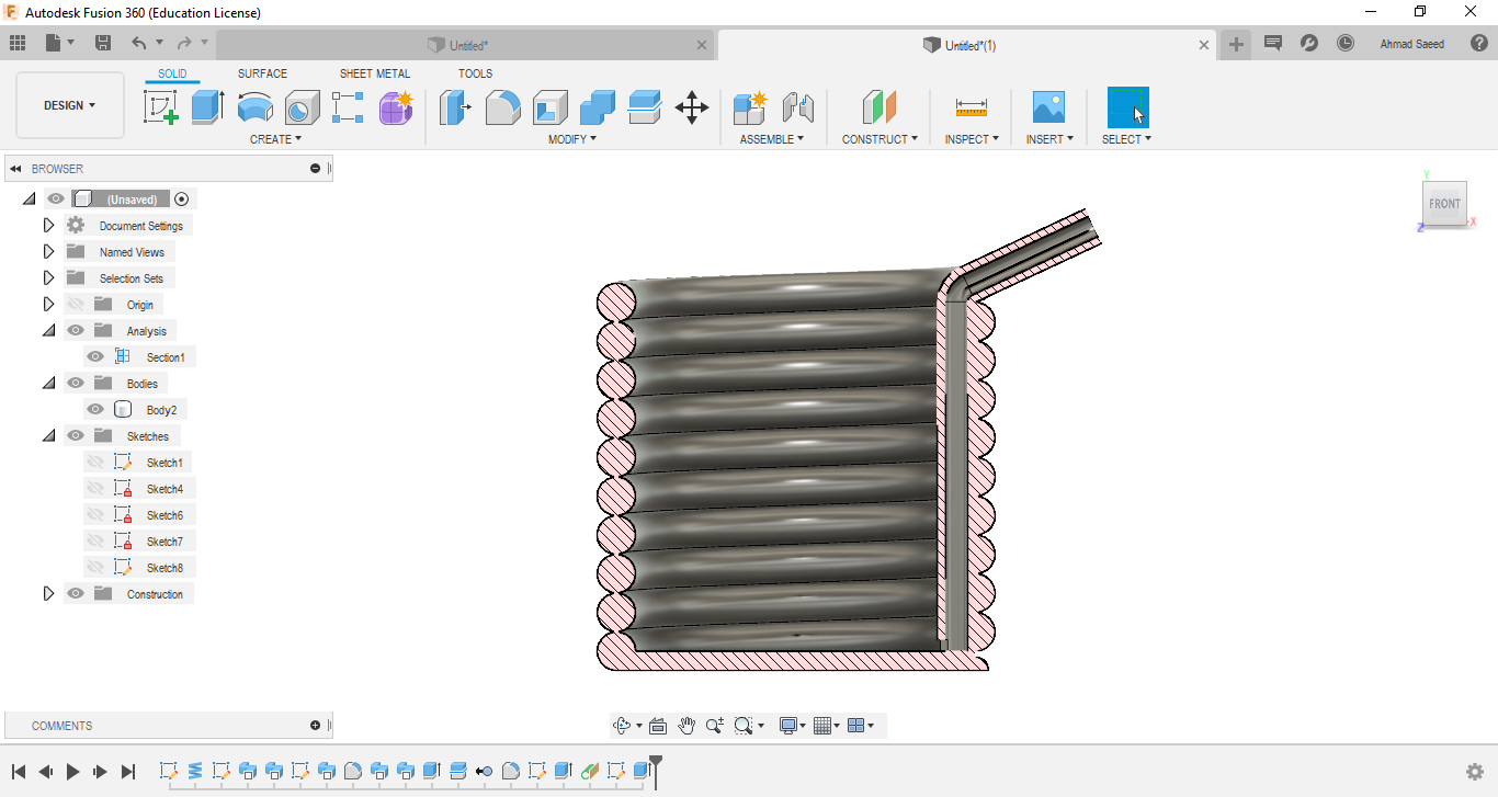
Remember the gap between the coil layers? I decided to join them just to be safe. I drew and extruded a thin border as in the photos.

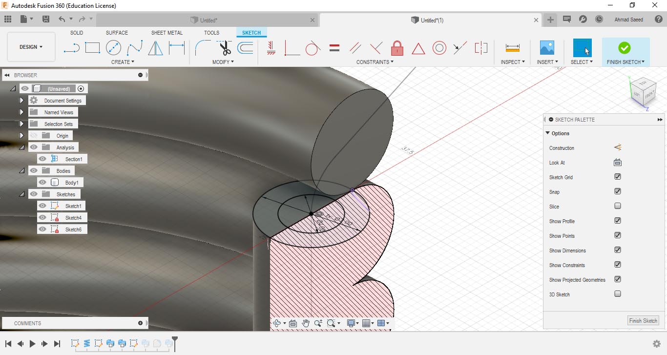
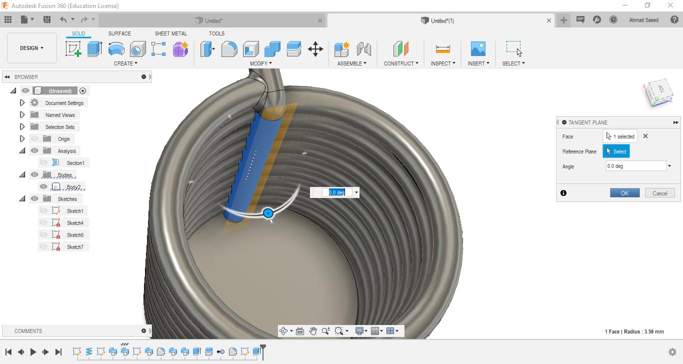
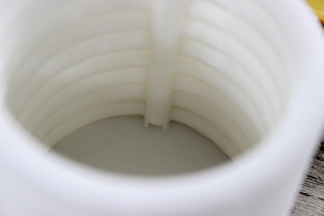
I added a hole by constructing a plane tangent to the straw, then extrude cut a rectangle at the bottom of it.

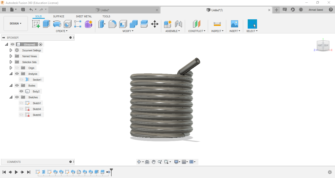
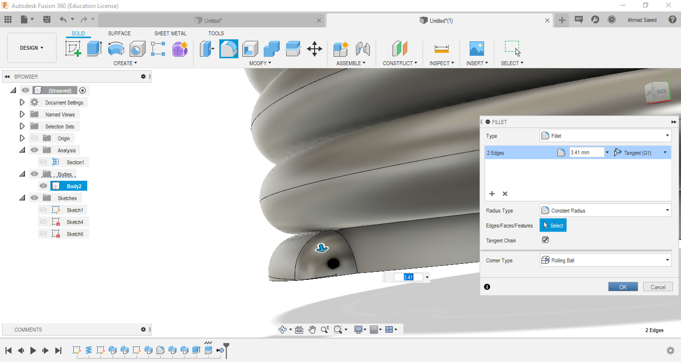
I also made the straw more fused to the cup structure using fillet feature.
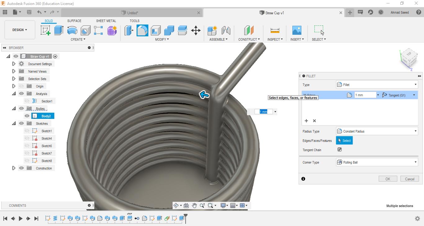
Everything is finally done :D :D

The last step was to export the file as STL to be ready for printing.
Here's the final 3D Part.
3D Printing my Files
Time for printing \o/
First I needed to slice the part to get the machine instructions file (*.gcode) that makes it able to do the right process to print my part. I used PrusaSlicer for that job.
I inserted the file inside the software. It wasn't in the right orientation, so I rotated it.

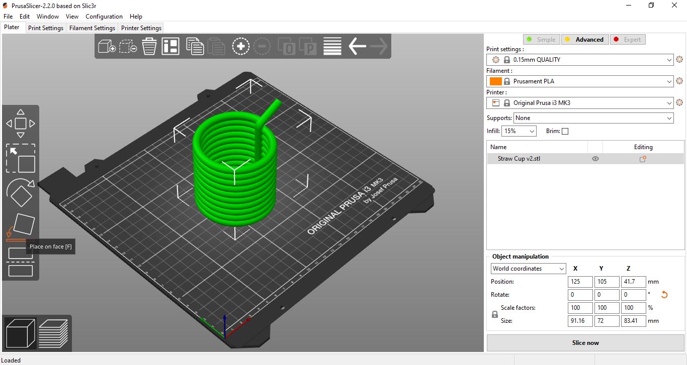
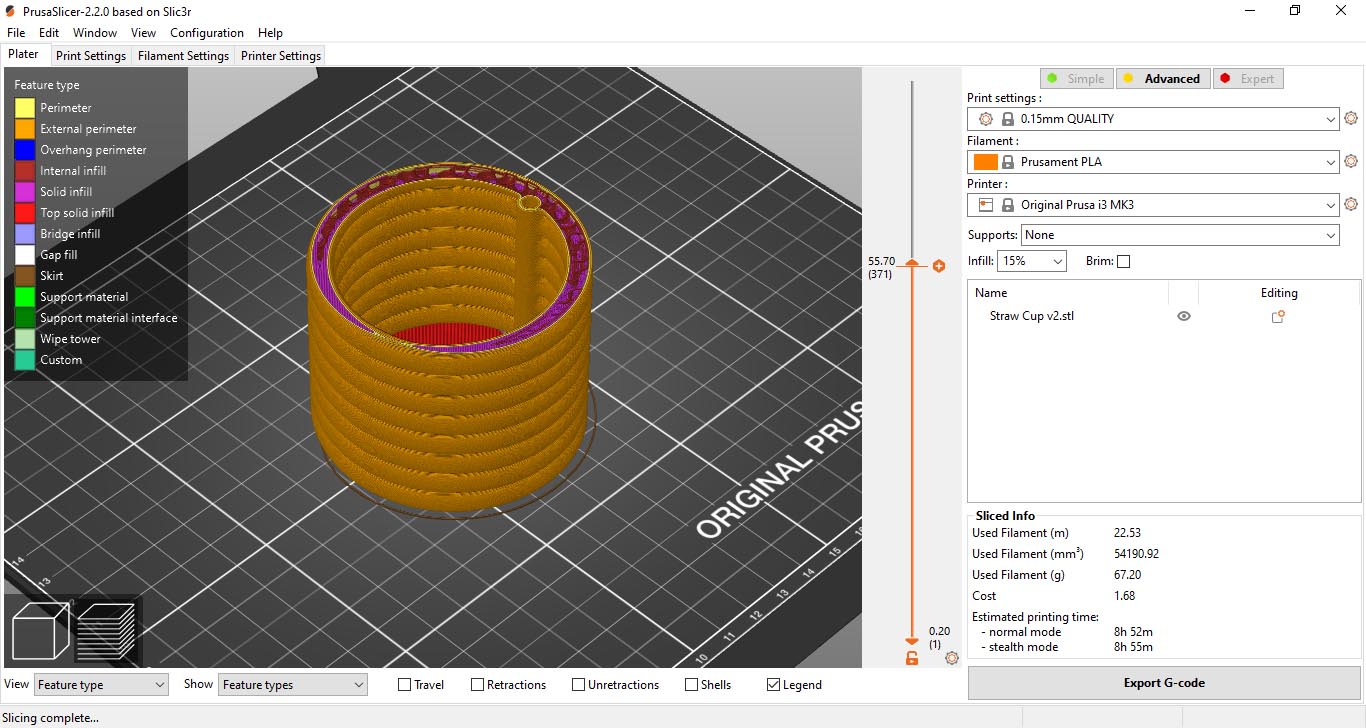
I tried to slice it with different parameters to get proper printing time.
I as settled at 0.3mm Layer Height - 15% Infill - No supports - No Brim
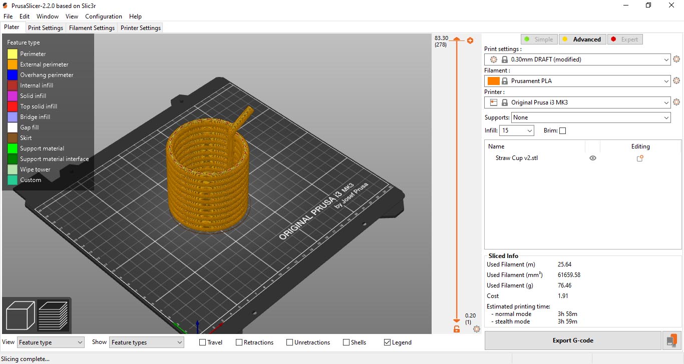
I exported the final sliced file into the printer's SD Card, and then started printing.

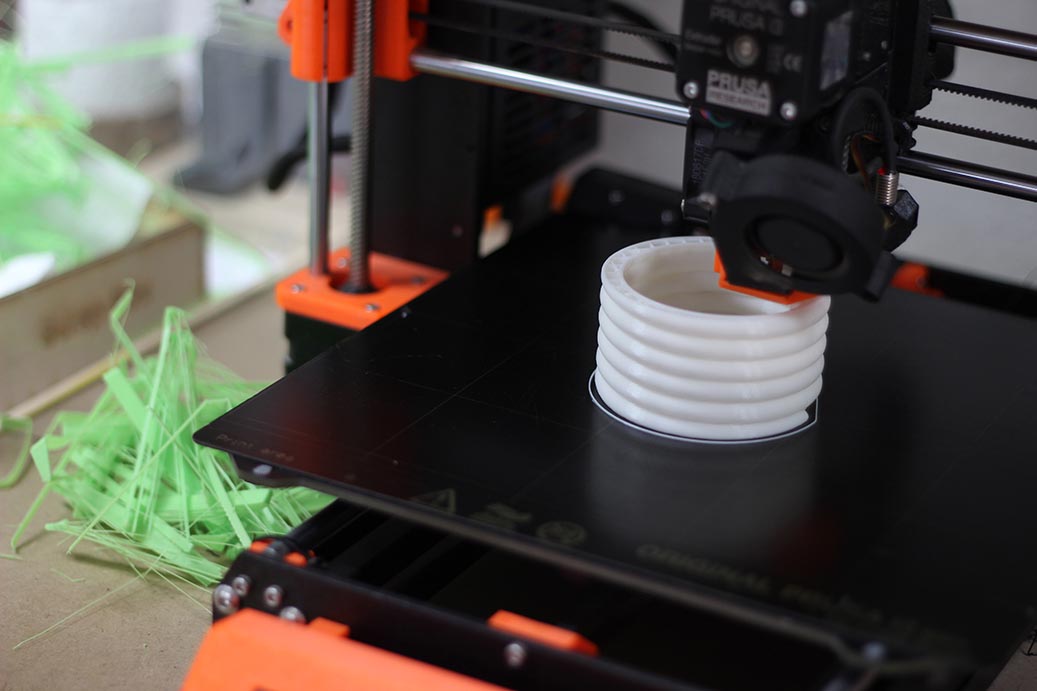
After 4 hours; the beautiful part came to life : )
3D Scanning
3D scanning is the process of analyzing a real-world object to collect data on its shape. There are many techniques of 3D Scanning; which varies in hardware and software requirements. I used Photogrammetry; which is basically getting normal photos of the object at different angles, and use a software to do the conversion magic.
Let me introduce to you my bath duck; Sawsan :D She has been always telling me that she wanted to be a model.
Sawsan is photogenic. She was really happy as I took 20 photos of here at different positions and angles. (I'm the one who was changing positions and angles)
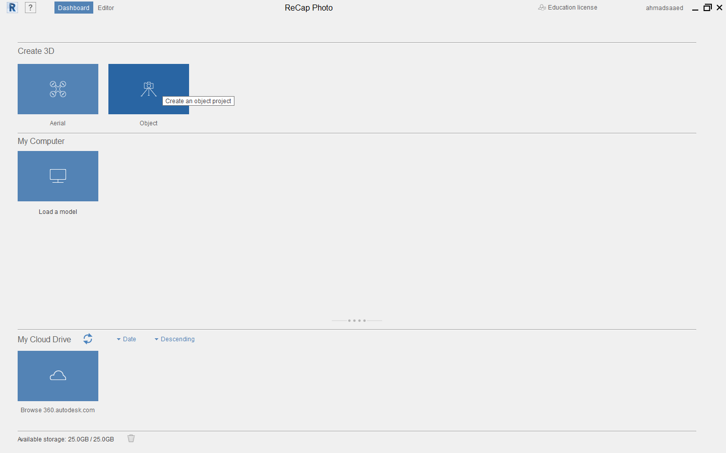
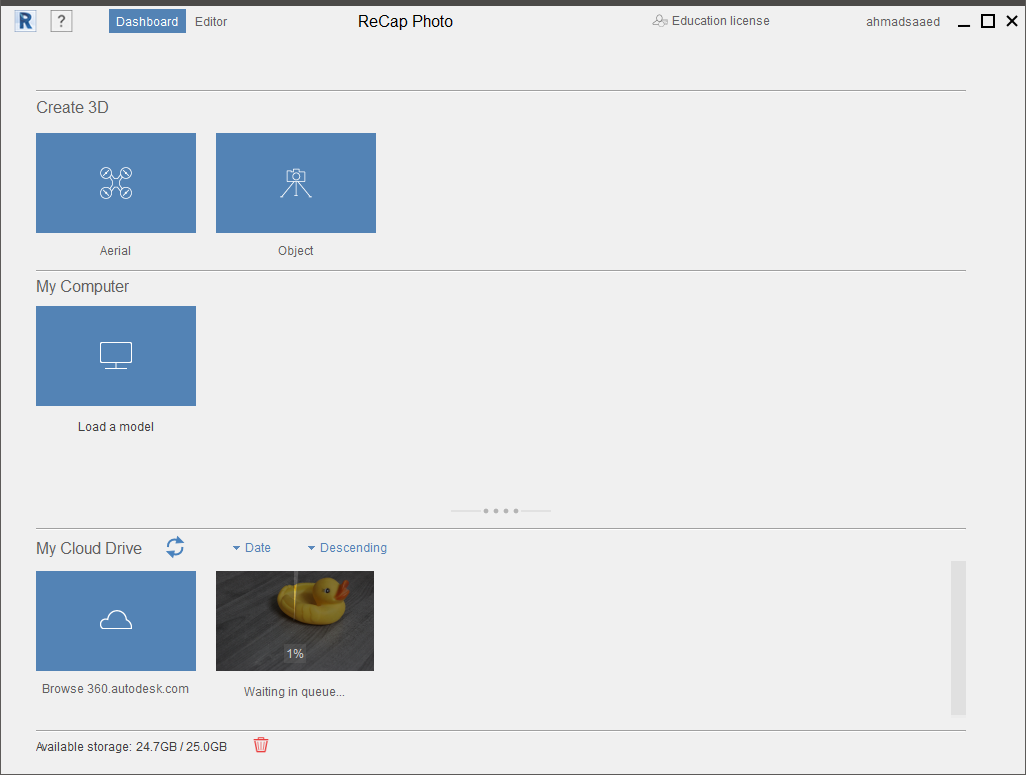
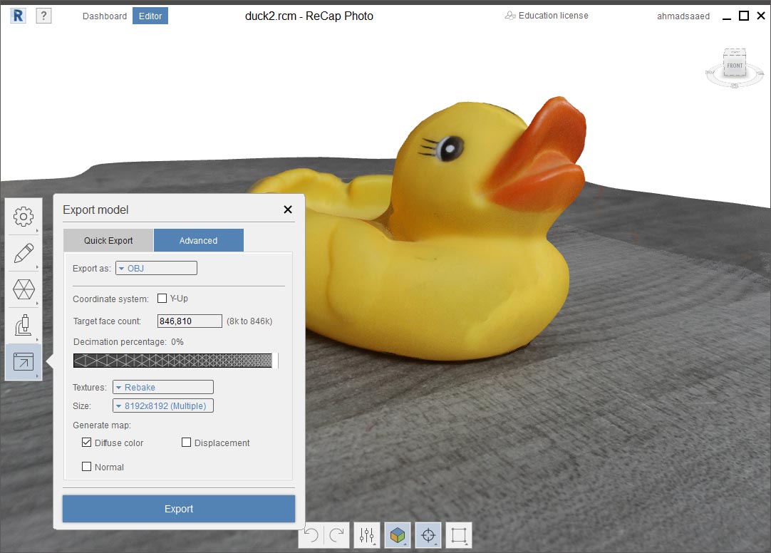
I used Autodesk ReCap Photo to do the magic.
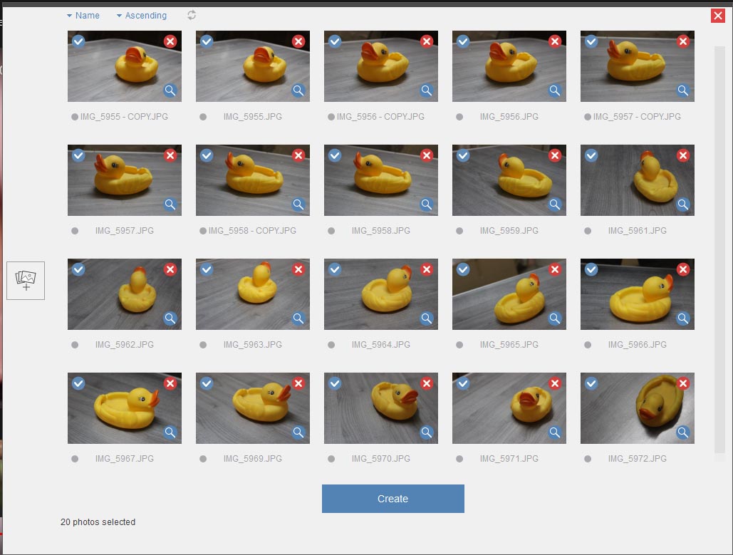
It took me around 30 minutes to upload the photos and get the processed file.
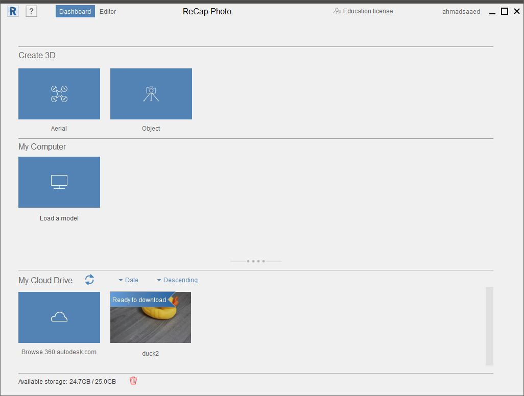
The file was really beautiful. Very proud of you my lovely Sawsan : )

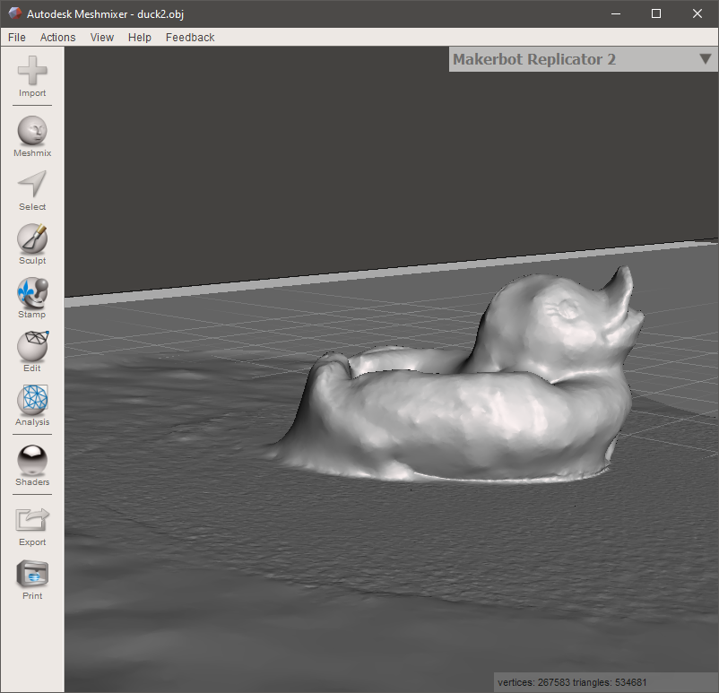
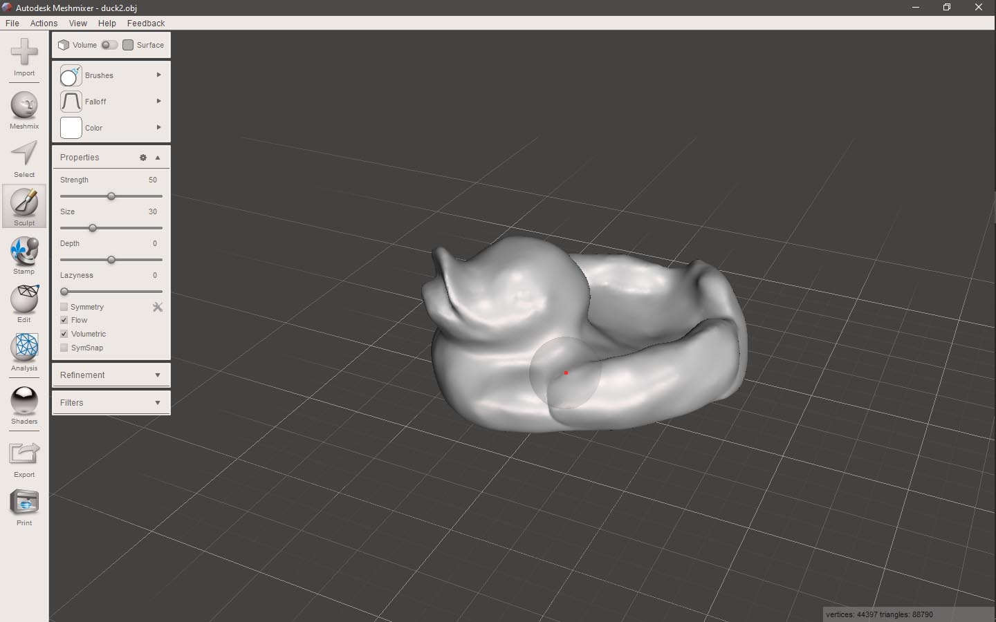
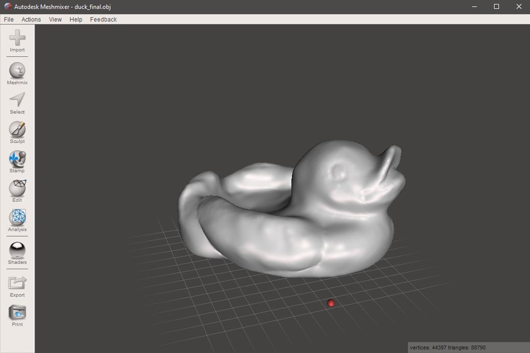
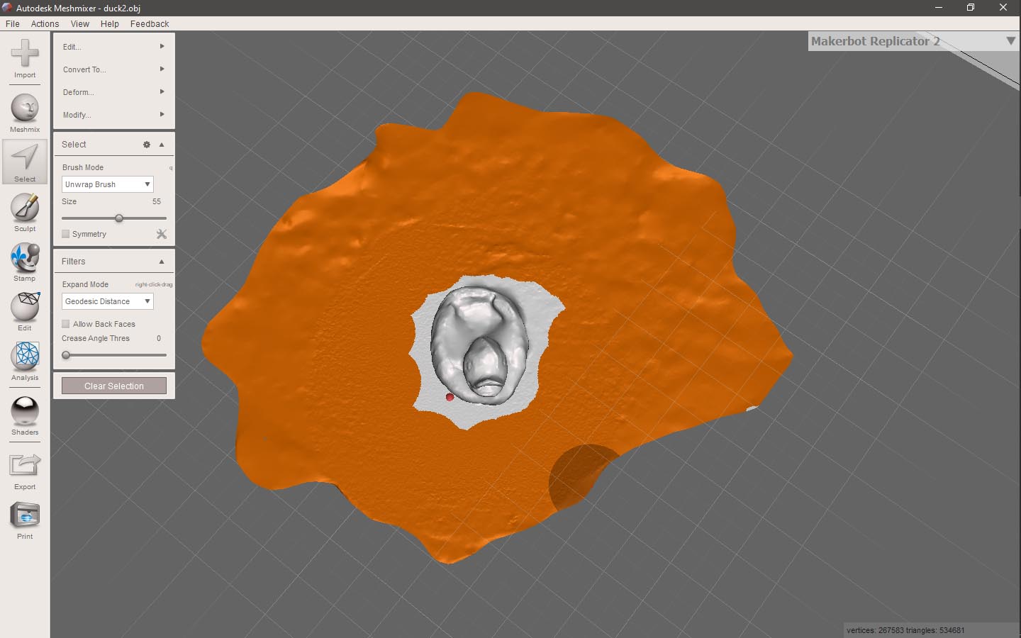
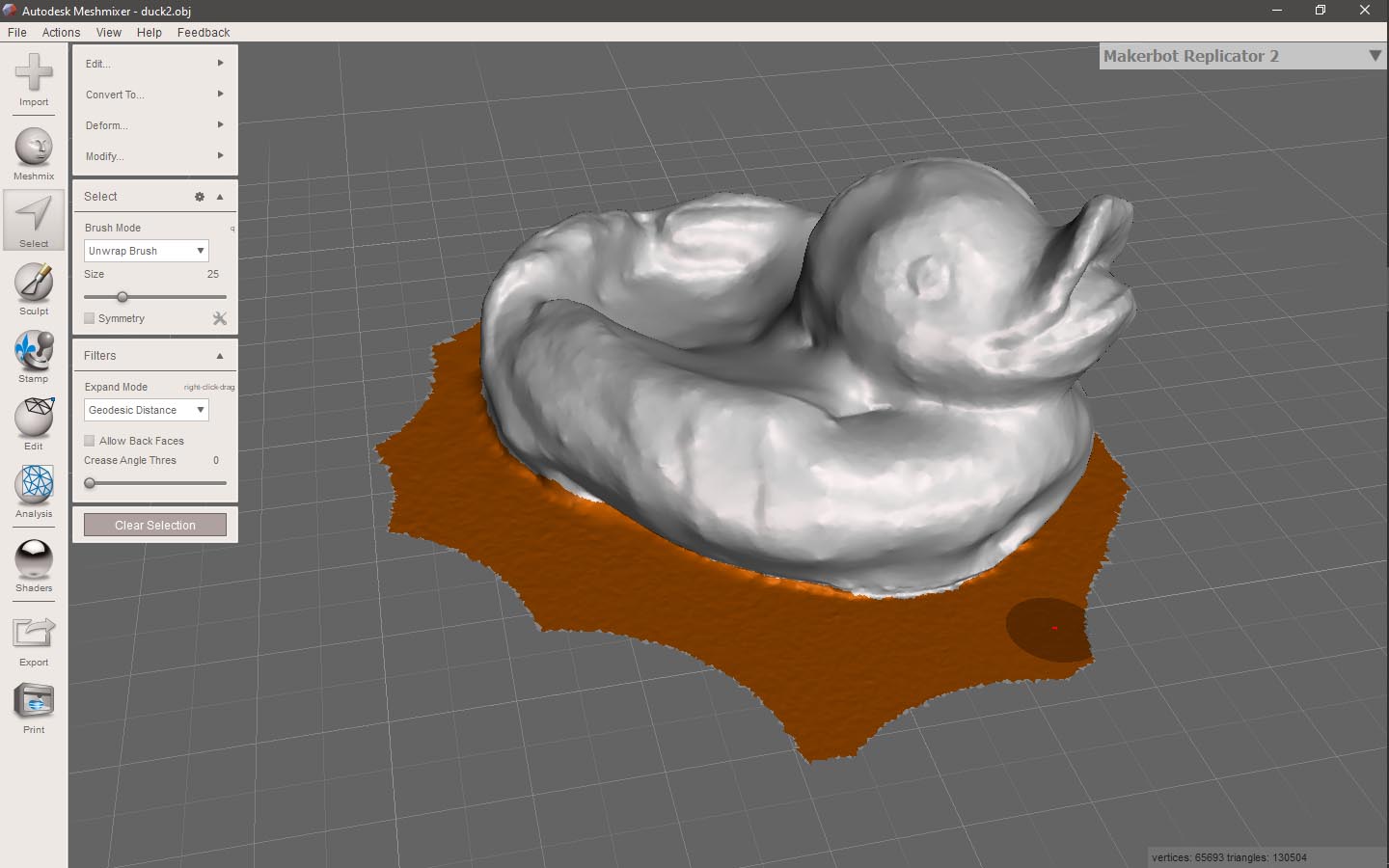
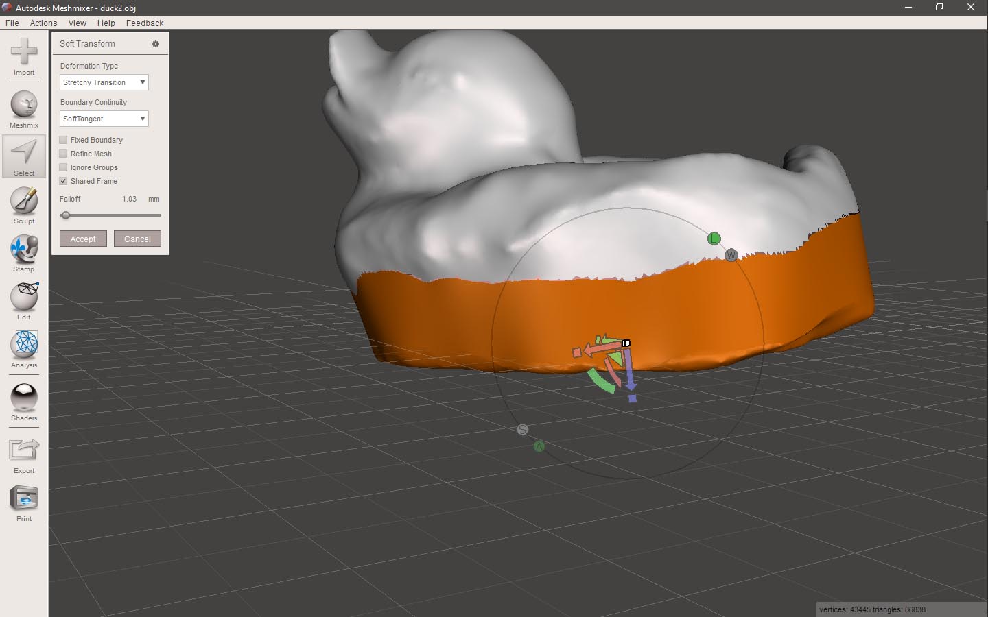
I used Meshmixer to refine the 3D model. I first selected and deleted the teble part.
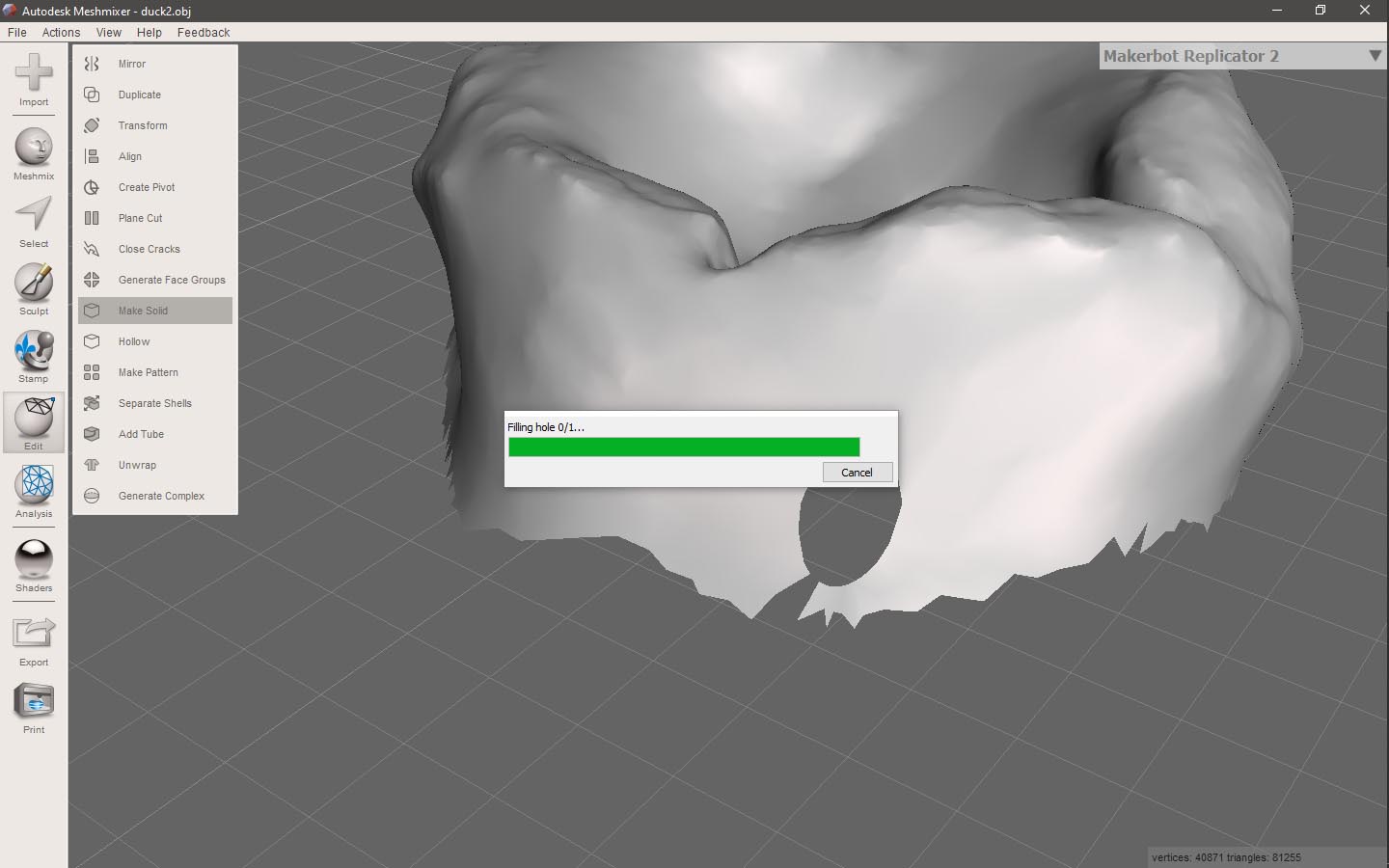
I then made the model solid from inside.
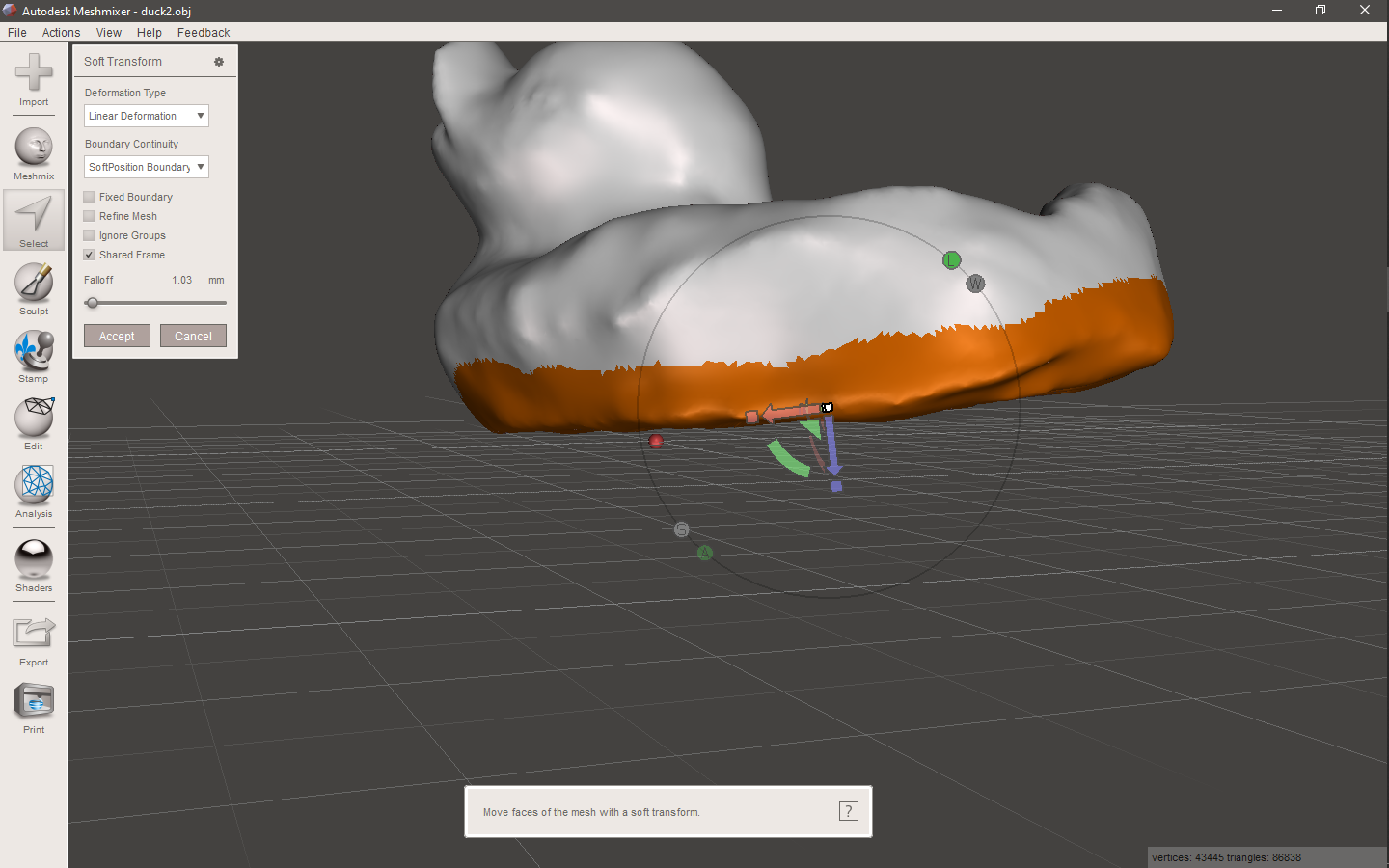
The bottom of the model wasn't flat, so I extruded the bottom surface- then cut it flat at the same original height.

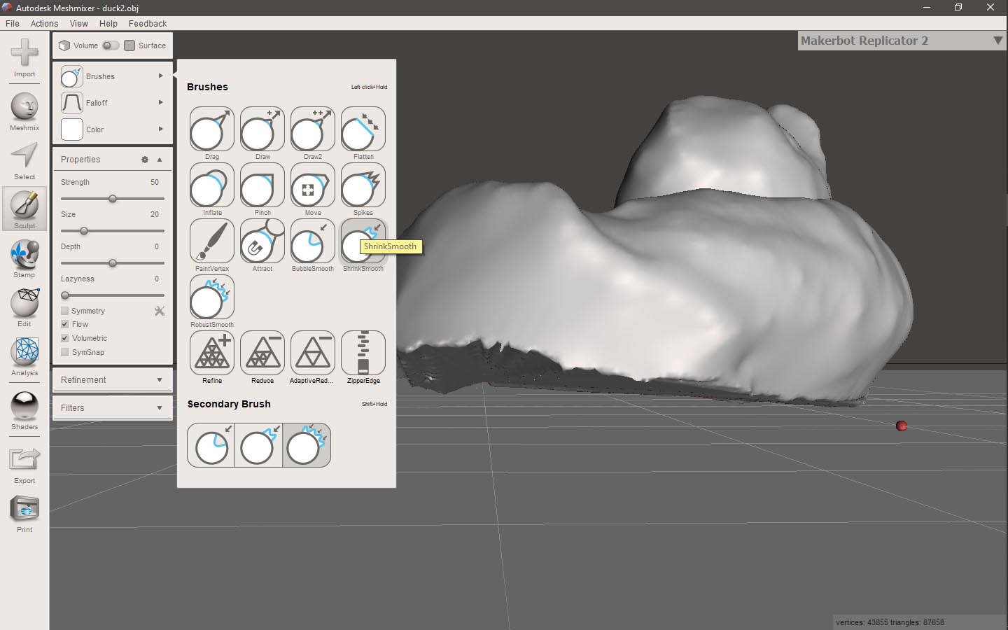
After playing with some brushes and tools- I got a really nice model of the lovely Sawsan : )