- Group Assignment:
- send a message between two projects
- Individual Assignment:
- design, build, and connect wired or wireless node(s)
with network or bus addresses
- design, build, and connect wired or wireless node(s)
- Link to the group assignment page
- Document my project
- Document what I learned from implementing networking and/or communication protocols
- Explain the programming process/es I used
- Outline problems and how I fixed them
- Included design files (or linked to where they are located if you are using a board you have designed and fabricated earlier) and original code.

Group Assignment
I have many development boards in my personal inventory, and I tried working with ESP8266 before, but I never tried the NodeMCU that I bought a while ago.
I decided to make a webpage where I can send a message from the NodeMCU when a pushbutton is pressed.
This simply can happen if I can make a self-reloading page that I can change its content with my message each time it refreshes itself.
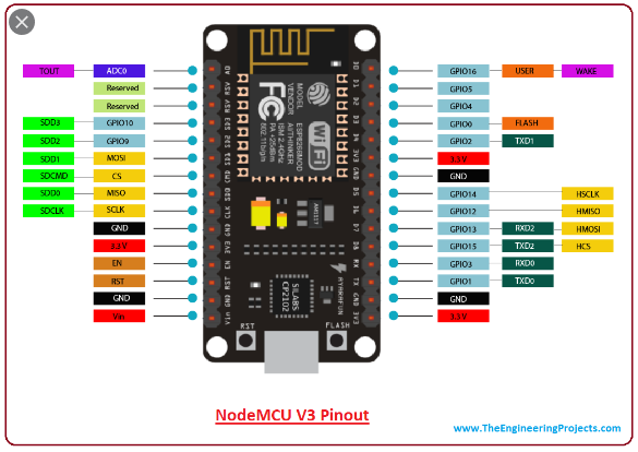
I started by wiring up a pushbutton between pin 5 of the NodeMCU and GND pin.
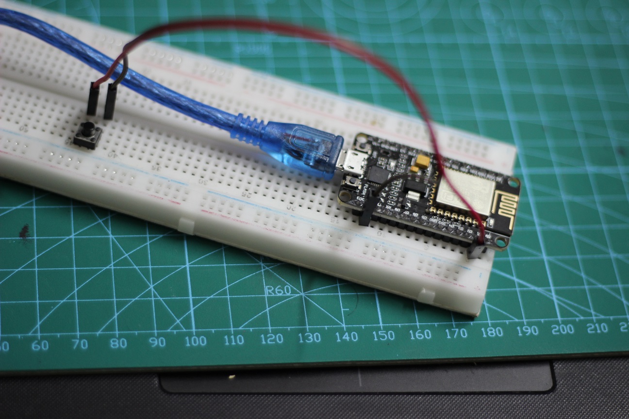
I knew the pin number by refereing to this pinout
Now it's time for coding. I used Arduino IDE as my compiler.
First we start by including the main two libraries for connecting to the ESP WiFi module and the methods that handles the HTTP requests at the low level.
#include <ESP8266WiFi.h>
#include <ESP8266WebServer.h>
Next, we specify the WiFi network settings that we would use, such as the network ID, password, IPs, and port.
/* SSID & Password */
const char* ssid = "saeed";
const char* password = "12345678";

/* IP Address details */
IPAddress local_ip(192,168,1,1);
IPAddress gateway(192,168,1,1);
IPAddress subnet(255,255,255,0);

ESP8266WebServer server(80);
In the setup function we initiate the button as input, and establish the WiFi network. We also link the main page to the root that the computer will connect to when we access the server IP.
void setup() {
    pinMode(5, INPUT_PULLUP);

    WiFi.softAP(ssid, password);
    WiFi.softAPConfig(local_ip, gateway, subnet);
    delay(100);

    server.on("/", handle_OnConnect);
    server.begin();
}
Now the tricky part. The HTML page that would be visible to the client is written here as a variable. It's a page that refreshes and recalls itself each half of a second allowing us to update the content of the page if we changed that variable at anytime.
String tmpString = "";
String html_1 = R"=====(
<!DOCTYPE html>
<html>
    <head>
        <meta http-equiv='refresh' content='0.5'>
        <title>Test Page</title>
    </head>

    <body>
        <div id='main'>
            <h2>Button State = %count%
        </div>
    </body>
</html>
)=====";

void handle_OnConnect() {
    server.send(200, "text/html", tmpString);
}
We finally check the button state in the main loop and change it in the string variable by replacing part of the string.
void loop() {
    server.handleClient();
    if (digitalRead(5) == HIGH){
        tmpString = html_1;
        tmpString.replace("%count%", "Not Pressed" );
        delay(200);
    }
    else {
        tmpString = html_1;
        tmpString.replace("%count%", "Pressed" );
        delay(200);
    }
}
You can find the full code in a single file in the downloads section below.
The code is uploaded to the ESP by installing its core to the Arduino IDE like I did in Week 8

Everything worked like a charm : )
Planning
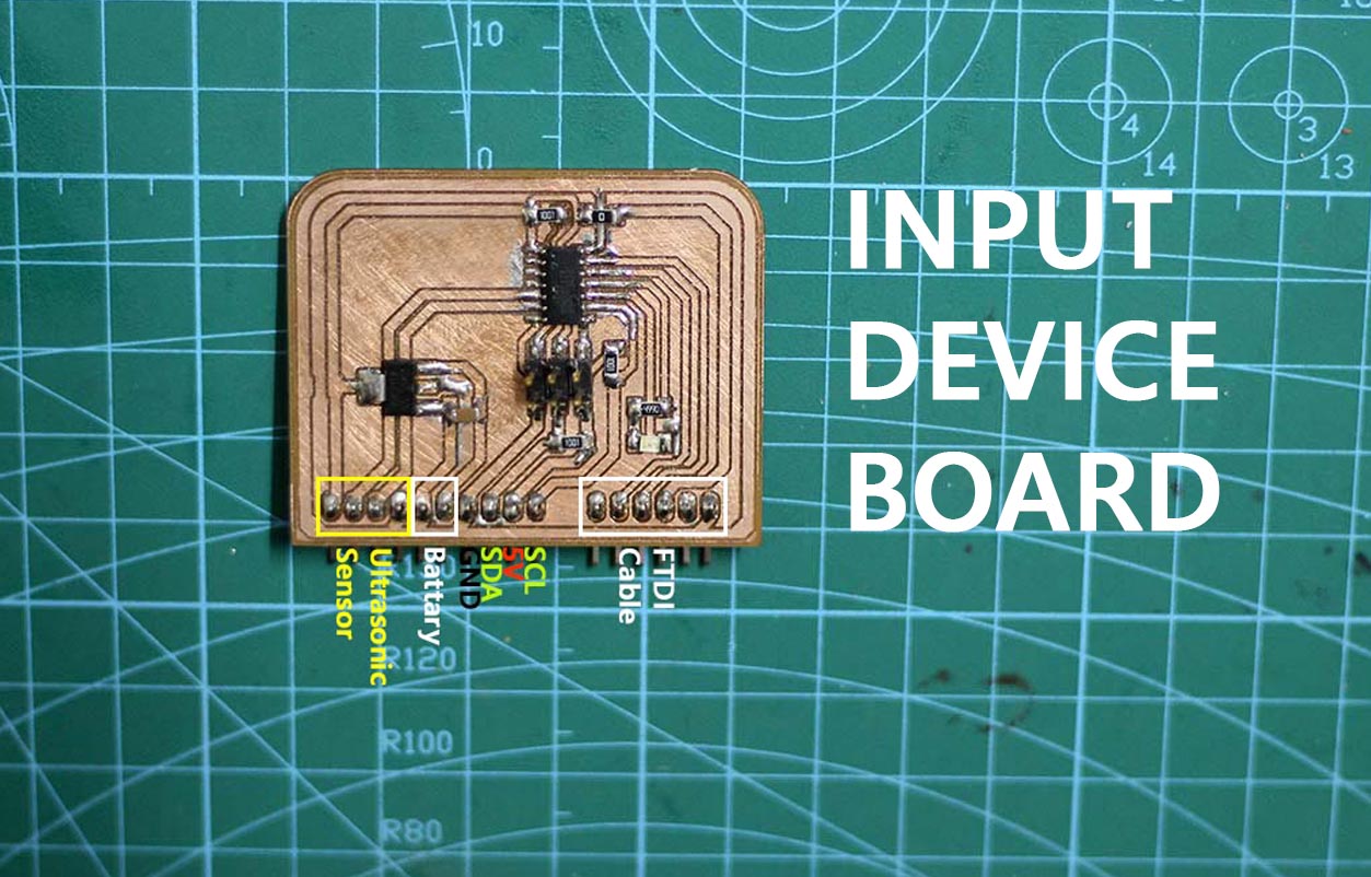
In the Input and Output devices assignments, I made two boards that share the same external pinout, and have an internal LED connected to the same pin. I'm planning to blink the two LEDs alternatingly by addressing each board to turn the LED on or off using I2C protocol.
I2C Protocol is a protocol intended to allow multiple "slave" circuits to communicate with one or more "master" circuits. Like the Serial Peripheral Interface (SPI), it is only intended for short distance communications within a single device. Like Asynchronous Serial Interfaces (such as RS-232 or UARTs), it only requires two signal wires to exchange information.
The protocol can be used easily by giving each slave device
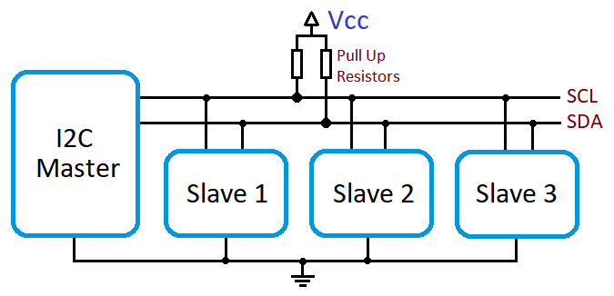
The protocol can be used easily by giving each slave device an ID, then the master would use that ID when sending a message to that particular device.
The plan is to do the following:
- Give each board a different address. 8 and 9 in our case.
- Make the master do the following:
- Tell board 8 to turn ON the LED, and board 9 to turn OFF the LED
- Wait a second
- Tell board 8 to turn OFF the LED, and board 9 to turn ON the LED
- Wait another second
Writing the Code
The Master Board Code: Arduino UNO Code
The Arduino I2C library automagically manages the data types of the messages sent. I would be sending and receiving characters to represent the desired LED state.
- O = LED ON
- S = LED OFF
#include <Wire.h>

void setup() {
  Wire.begin();
}

void loop() {
  Wire.beginTransmission(8);
  Wire.write('O');
  Wire.endTransmission();
  Wire.beginTransmission(9);
  Wire.write('S');
  Wire.endTransmission();
  delay(1000);

  Wire.beginTransmission(8);
  Wire.write('S');
  Wire.endTransmission();
  Wire.beginTransmission(9);
  Wire.write('O');
  Wire.endTransmission();
  delay(1000);
}
The Slave Board Code: ATtiny44
The Wire.h library wouldn't work with the ATtiny44 MCUs, so I downloaded and used the TinyWire.h library.
In the code I wait for an I2C message. If the coming character is O, I turn the LED ON, else, I turn in OFF.
#include <TinyWire.h>

const int ledPin =  2;

void onI2CReceive(int howMany)

void setup() {
  pinMode(ledPin, OUTPUT);
  digitalWrite(ledPin, LOW);

  TinyWire.begin( 9 );
  TinyWire.onReceive( onI2CReceive );
}

void loop() {
  while (TinyWire.available()) {
    char msg = TinyWire.read();
    if (msg == 'O') digitalWrite(ledPin, HIGH);
    if (msg == 'S') digitalWrite(ledPin, LOW);
  }
}
The code would be the same for both boards, except for the address in the setup function. I used address 8 with one board, and 9 with the other one.
Testing
As I mentioned before, the two boards share the same pinout, so I only needed to:
- Upload the code to each board separately
- Connect the two boards to the Master Arduino Uno board using I2C
I used the programmer I made in Week 4 to upload my codes to the two boards using the Arduino IDE. I also used Arduino IDE to upload the Master code to the UNO.
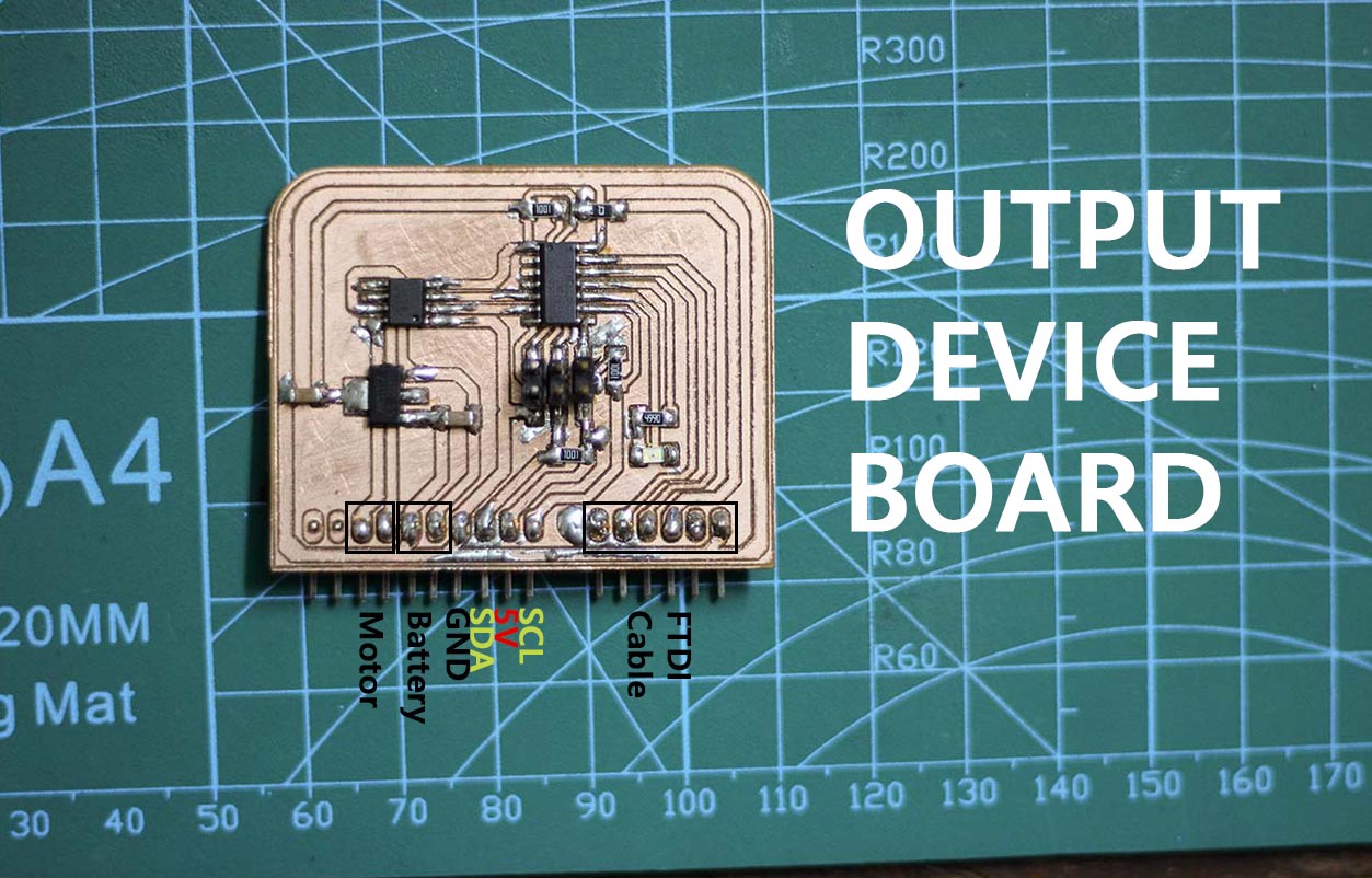
I used 4 jumper wires to connect the two power pins and the other two I2C pins to my boards. I also used a small breadboard like in the following photos.

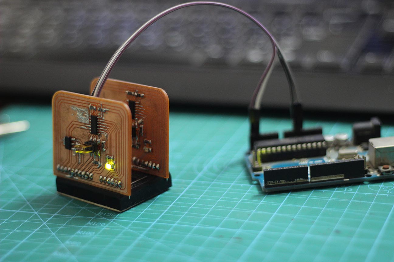
Here's a video for the results:
Downloads