Design and produce something with a digital fabrication process
(incorporating computer-aided design and manufacturing) not covered
in another assignment, documenting the requirements that your
assignment meets, and including everything necessary to reproduce it.
- Document how I made my creation
- Describe problems and how I fixed them
- Include my design files and ‘hero shot’ of the result
Summary
Conventional programming interfaces makes it very time-consuming to program a robot arm to do a complex task. Today it's possible to program robots from other interfaces and even using integrated extensions on many CAD programs; which can generate long files of robot language. Many manufacturers even made it possible for their robots to understand G-Code lines generated from conventional CAM software.
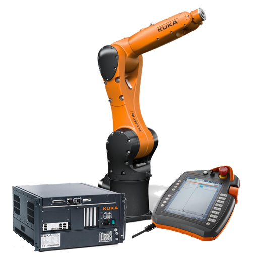
I had access to a
KUKA KR6 R900 sixx robot. It's a small scale industrial robot arm from the German manufacturer "KUKA". It can be conventionally programmed
through a touch interface called the "Teach Pendant" and using a language called "KRL, short for KUKA Robot Language".
I forked an open-source Inkscape Extension for generating g-code, and made it convert the contours of text and images in Inkscape to KRL Code that can run on KUKA controllers.
How to reproduce it
1: Adding the extension to Inkscape
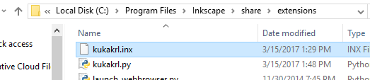
To install the extension:- Download kukakrl.inx and kukakrl.py
- Copy the files into the extensions directory shown in the picture below
2: Using the extension to convert Text to KRL
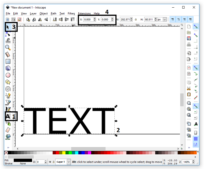
- Write your text with the text tool. The bottom left corner is the 0,0 location of the defined base or offset.
- Mark and position your text. If you have more objects (lines, circles, …) to embed in your KRL Code, you have to mark them all. Only marked objects will be used to generate the KRL Code.
- Click
Path -> Object to Pathor pressShift + Ctrl + Cto convert the text into a path. The Plugin will use this path to generate the KRL Code. - Click
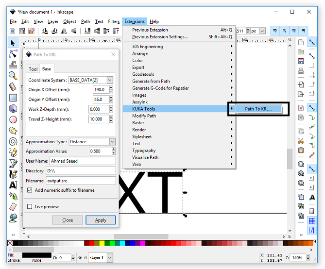
Extensions -> KUKA Tools -> Path to KRLto start our plugin. - Enter the proper settings.
- Click Apply to generate the KRL Code.
- After that the KRL Code will be stored and the motion path will be outlined.
- Copy and run the code on the KUKA controller.

3: User Guide to extension settings
- Tool:
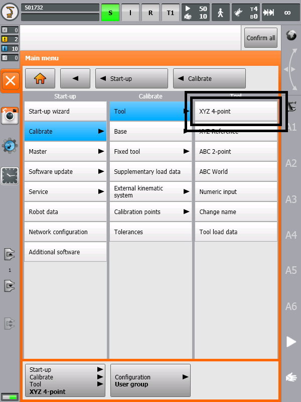
- Automatically be calling the data variables created after performing any of the tool calibration processes from
Start-up -> Calibrate -> Tool.
Example:$TOOL = TOOL_DATA[1]where 1 is the saved tool number. - Manually by entering their numeric XYZABC offset and orientation values.
Example:$TOOL = {X 280, Y 0, Z -10, A 30, B 90, C 0}where XYZ is the translational offset, and the ABC are Euler angles between the new base and the FLANGE coordinate system. - A° B° C° Orientation Angles (Euler Angles):
- Rotating the tool about its z-axis with an angle A (90 degrees)
- Rotating the tool about its y-axis with an angle B (180 degrees)
- Work Speed (Feedrate):
- Travel Speed:
- Coordinate System:
- Origin X, and Y Offset:
- Work Z-Depth:
- Travel Z-Height:
- Approximation Type:
- Distance:
A translational distance can be assigned to the variable
$APO.CDIS. If the approximate positioning is triggered by this variable, the controller leaves the individual block contour, at the earliest, when the distance from the end point falls below the value in$APO.CDIS. Its value is expressed in millimeters. - Velocity:
A percentage value can be assigned to the variable
$APO.CVEL. This value specifies the percentage of the programmed velocity$VELat which the approximate positioning process is started, at the earliest, in the deceleration phase of the individual block. The component which, during the motion, reaches or comes closest to the programmed velocity value, is then evaluated in terms of translation, swivel and rotation. Its value is expressed in integer number percentage. - Orientation:
An orientation distance can be assigned to the variable
$APO.CORI. In this case, the individual block contour is left, at the earliest, when the dominant orientation angle (swiveling or rotation of the longitudinal tool axis) falls below the angle distance, defined in$APO.CORI, from the programmed approximate positioning point. Its value is expressed in degrees. - Approximation Value:
- User Name:
- Directory:
- File Name:
- Add numeric suffix to filename:
Under most circumstances, a KUKA user first defines the TOOL and the BASE then refers to them in KRL using $TOOL, and $BASE system variables. The Tool can be defined through one of these two main procedures:
For this extension, you can only choose the tool number that matches yours, but if you desire to write the values manually, you can edit the created SRC file and add your values.
Defines the relative orientation of the selected tool relative to the selected base in certain motion path.
Example: LIN {X 0, Y 0, Z 0, A 90, B 180, C 0}
This transformation can be performed by:
Note that the ABC angles are the same as Euler angles, but with a little bit different names, as the rotation about tool’s z-axis is named C in Euler’s.
Defines the velocity at which the robot's TCP is moving while moving according to the desired path. It is expressed in units of Meter Per Second.
Defines the velocity at which the robot's TCP is moving while jumping from a path to another. It is also expressed in units of Meter Per Second.
Defines the desired Base number. The idea behind this is typically similar to the Tool in section 4.1.
Defines the shift from the selected base origin along the x-axis and y-axis. It is expressed in millimeters.
Defines the desired TCP's Z-axis value when the TCP is moving according to the desired path. It is expressed in millimeters.
Defines the desired TCP's Z-axis value when the TCP is jumping from a path to another. It is expressed in millimeters.
In order to increase velocity, avoid jerky motion, and achieve continuous motion along complex paths, points for which exact positioning is not necessary can be approximated. The robot takes a shortcut as illustrated below.
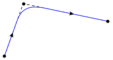
The various approximation motions are:
Defines the value of the selected approximation type. The greater the value of approximation, the more the path is rounded. You can get fine results by setting the its value to 0.5 for Distance type approximation.
Defines the name of the user making this path. It'll be added as a comment in the code's header.
Defines the folder at which the output file will be located.
Defines the name of the output file. It should be ended with .src
Adds a number at the end of the file name to allow multiple files with the same name to be saved in the same directory. So for instance, if the file name is output.src, it will be saved like output_0001.src
4: Running the file on the KUKA robot
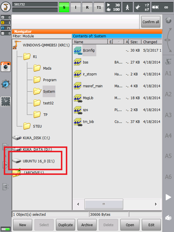
- The robot controller offers various user groups with different functions. The
Expertuser groups should be selected. - Insert a flash memory, containing the exported file, into the robot contoller. The memory stick would appear as a new drive. Copy your file into the controller.
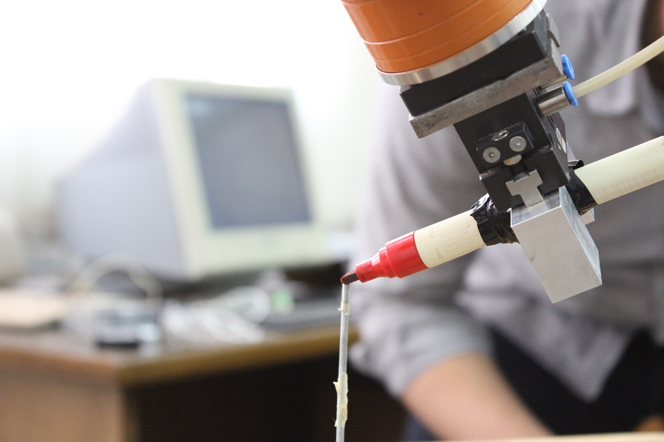
- Attach the pen to the robot's end effector
- If you haven't calibrated your base and tool, you should follow the instructions shown on the controller window to do that.
- Finally, just run your file. Try it on T1 mode at first just to make sure everything is okay.