- Group Assignment:
- Test runout, alignment, speeds, feeds, and toolpaths for the machine
- Individual Assignment:
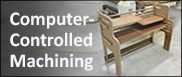
- Make (design+mill+assemble) something big
- Link to the group assignment page
- Document how I designed my object (something big)
- Document how I made my CAM-toolpath
- Document how I made something BIG (setting up the machine, using fixings, testing joints, adjusting feeds and speeds, depth of cut etc.)
- Describe problems and how I fixed them
- Include my design files and ‘hero shot’ photos of final object

Group Assignment
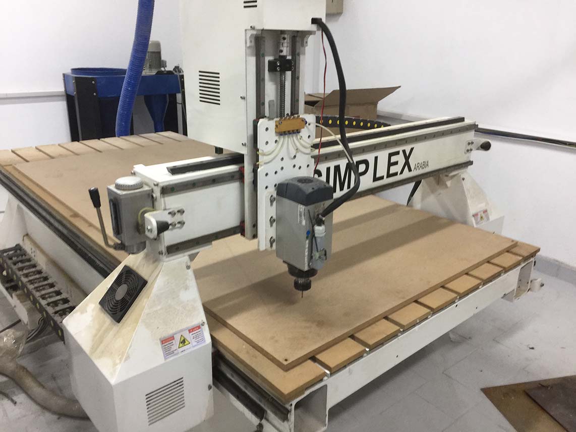
This is SIMPLEX STANDARD Router Machine.
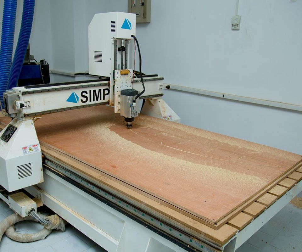
It's a Full Sheet CNC Router- with MACH3 Interface. The input for MACH3 machine is *.gcode file, exported from one of any toolpath generating software.
The MACH3 Interface also enables controlling the machine directly using a normal keyboard; in order to adjust the xy-origin point and calibrate z-height.
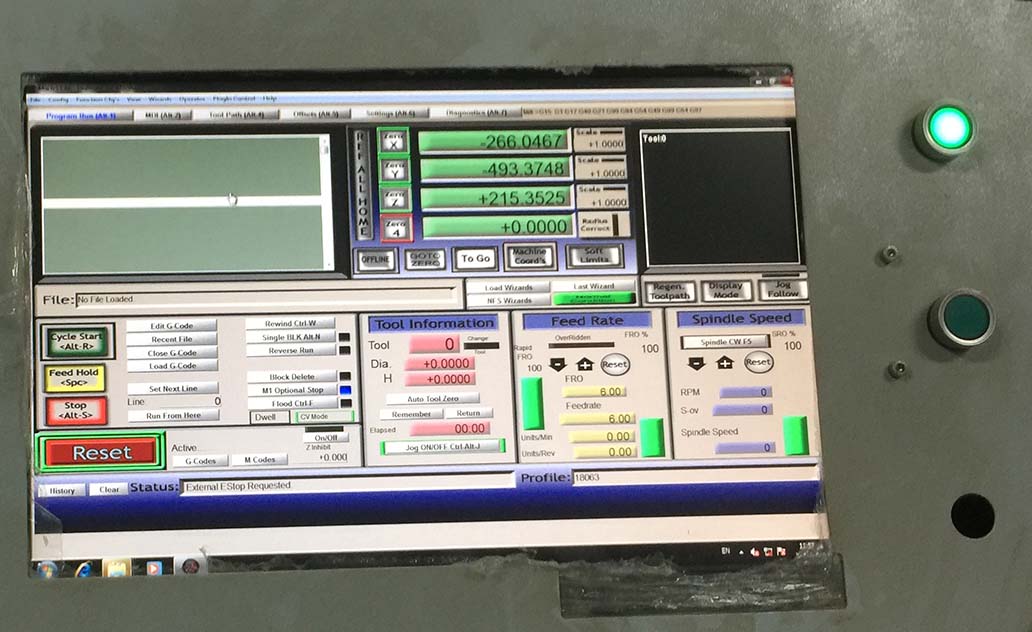
The machine had a wooden bed which was totally engraved to ensure the bed level alignment.
Before operating the machine, we tested the runout using a dial gauge.
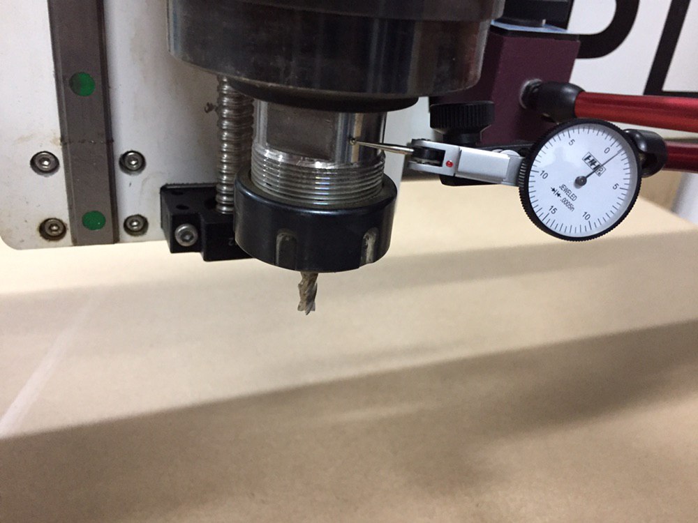
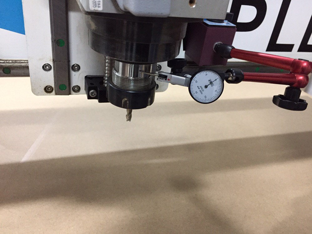
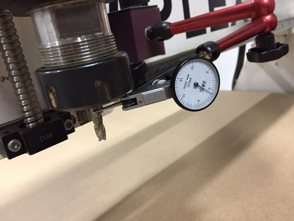
It shows that the machine has around 1mil eccentricity, which is fine for our applications and can be easily tolerated.
Inspiration and Planning
Sitting in the office for long time really bothers me. I read many articles about Standing Desks and wanted to try one, but they are relatively expensive because they usually are made of metals and have height complex height adjustment mechanisms.
This week's assignment was to make something big! I thought I might design and make a fixed-height and low-cost standing desk which is customized for me. I searched about wooden versions of standing desks, and I liked this design.
It's a desk extension that can hold up my devices to the desired height.

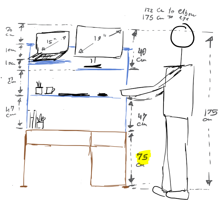
I made a draft sketch of what dimensions should I use according to the dimensions of my body height, my desk, my laptop, and my screen according to this guide.
When using a standing workstation, keep your head, neck, torso and legs approximately in line and vertical. Use a footrest to shift your weight from foot to foot.
Desk
Choose a desk deep enough to allow your monitor to fit directly in front of you and at least 51 centimeters away. The desk should allow you to keep your wrists straight and your hands at or slightly below the level of your elbows.
Monitor
Place the monitor directly in front of you, about an arm's length away. The top of the screen should be at or slightly below eye level.
Keyboard and mouse
Place your mouse and keyboard on the same surface and at a distance that allows you to keep your elbows close to your body. While typing or using your mouse, keep your wrists straight, your upper arms close to your body, and your hands at or slightly below the level of your elbows.
I am 193cm tall. When I'm standing on one leg, my eyes are 175cm from the ground. I also had:
- 75cm normal desk
- 15'' laptop
- 19' laptop
- Mouse and Keyboard
Design of CAD Model
Design for CNC Router
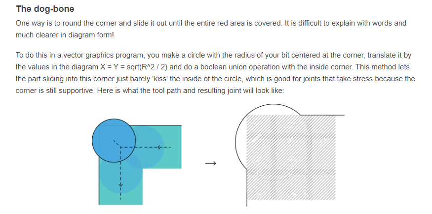
I've never designed anything for the CNC before. The concept of corner-compensation was new for me. In short, CNC cut corners leave a radius on inside corners. There are various techniques to deal with this issue.
Two common solutions to deal with that issue are the dog-bone and the T-bone. The T-bone is straight forward to implement, but the dog-bone is somehow tricky. I found the an easy guide for its implementation.
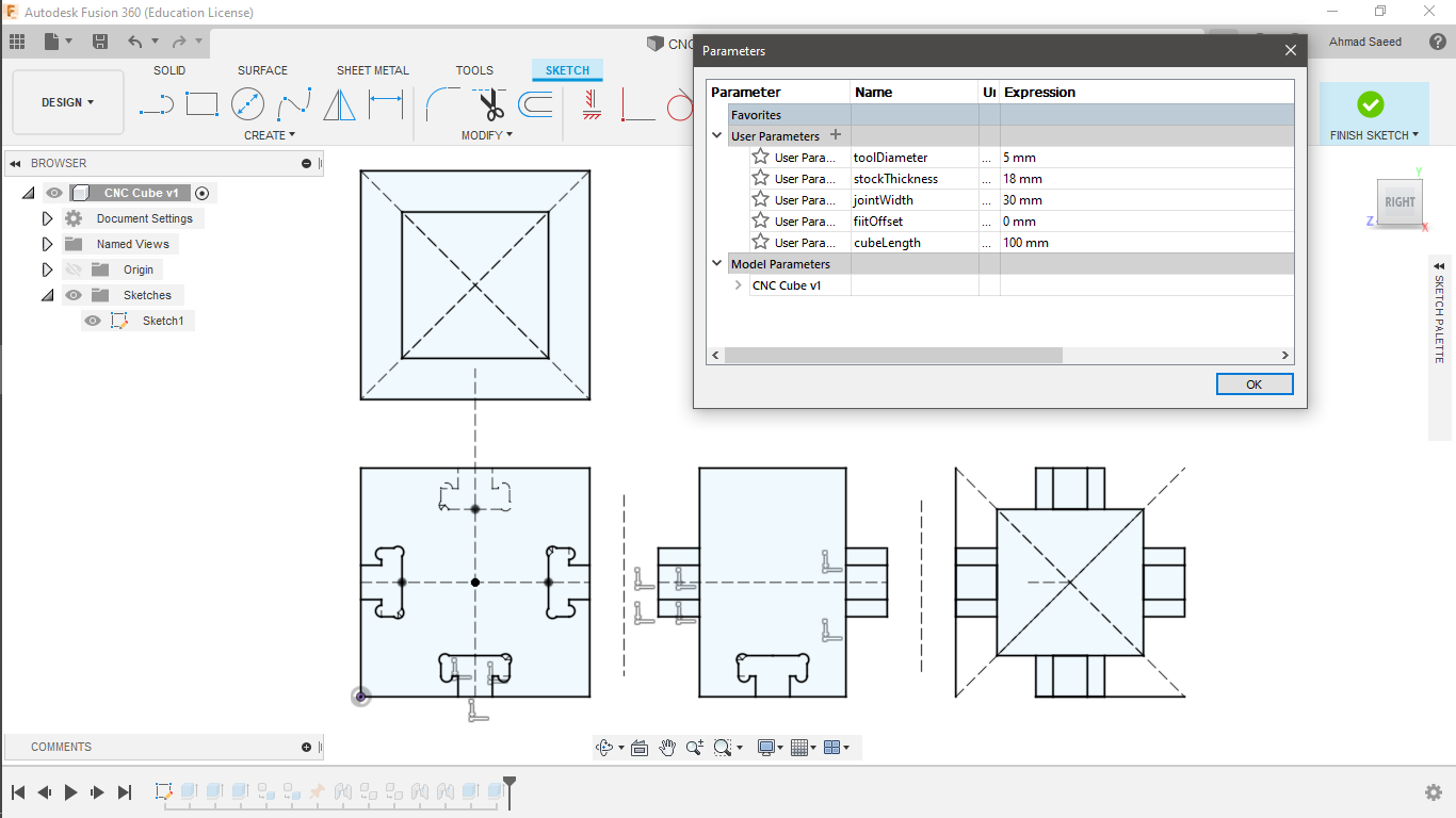
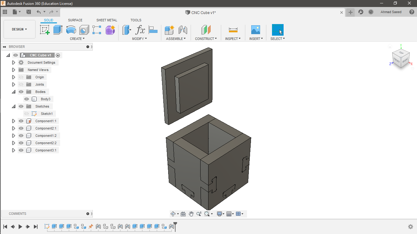
Since it was my first time to design fits with corner-compensation , I tried to design a small box that can be edited with parameters. I used both dog-bone and T-bone in my design- just to get used to it.
- The Tool Diameter affects corner compensation.
- The Stock Thikness is important to have a hammer fit.
- The Fit Offset represents the runout.
- The Cube Length represents the uniform dimensions of our cubes' length, width, and height.
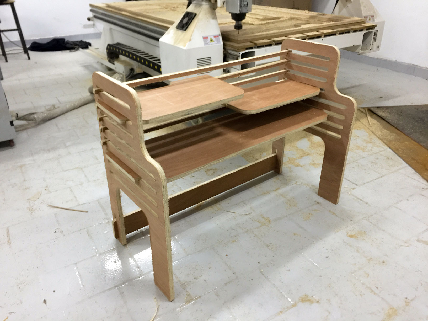
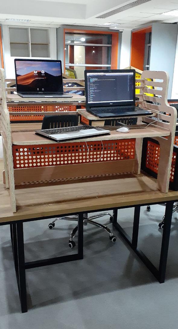
Creating the Desk
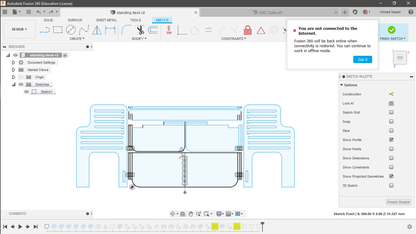
After spending time learning about the design rule for CNC routing, I got ready to design my desk.
The desk parts are pretty simple to design. It is consisted of two sides, three adjustable shelves, and some back supports.
I started my design with the main shelf; where my mouse and keyboard should be located.
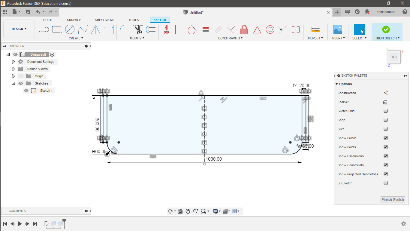

I then created the two smaller shelves for the screen and the laptop. When I do 2D design, I like to design all the parts in the same sketch; so that I could export them easily one time.
I sketched and extruded the two other shelves like so.

Now it's time to add the two sides, and make sure that the shelves dimensions fit.
It came right from the first time.
Finally, I added the back supports to the desk. I felt that the thinner bars might get broken during the routing process, but anyways I was going to try that.
Here's the final sketch of all the parts.
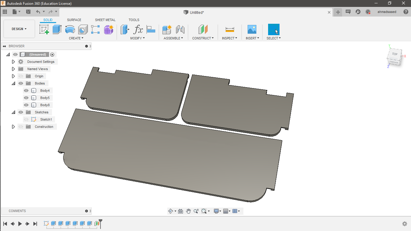
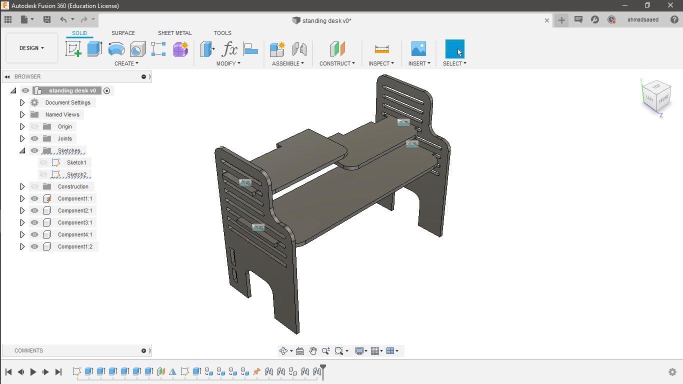
.. and the final awesome 3D Model of Fusion360
Generating CAM-toolpath
Any digital fabrication machine doesn't understand your design, surprise? Machines contain motors that simply follow the electrical signals of the machine controller hardware- amplified by their drivers. The machine controller usually doesn't understand your design neither, and needs every line of motion to be written separately in a file (usually called a *.gcode file). In this case, we need a piece of software, called "toolpath generator", to convert the design into separate machine motions and export them into a file.
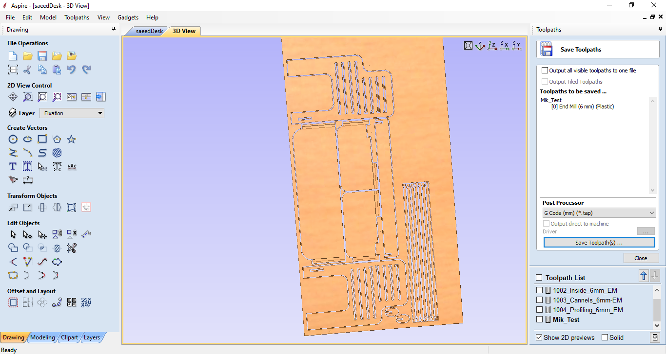
One generator is called Aspire. Aspire is software solution for creating and cutting parts on a CNC router. You load your design, set some parameters, and you're ready to do the job.
I started by loading my design. Notice the three different colored set of lines:
- Black lines are the part outlines.
- Red lines represent internal cut and pockets.
- Blue lines are for the engraved parts that should be cut halfway through.
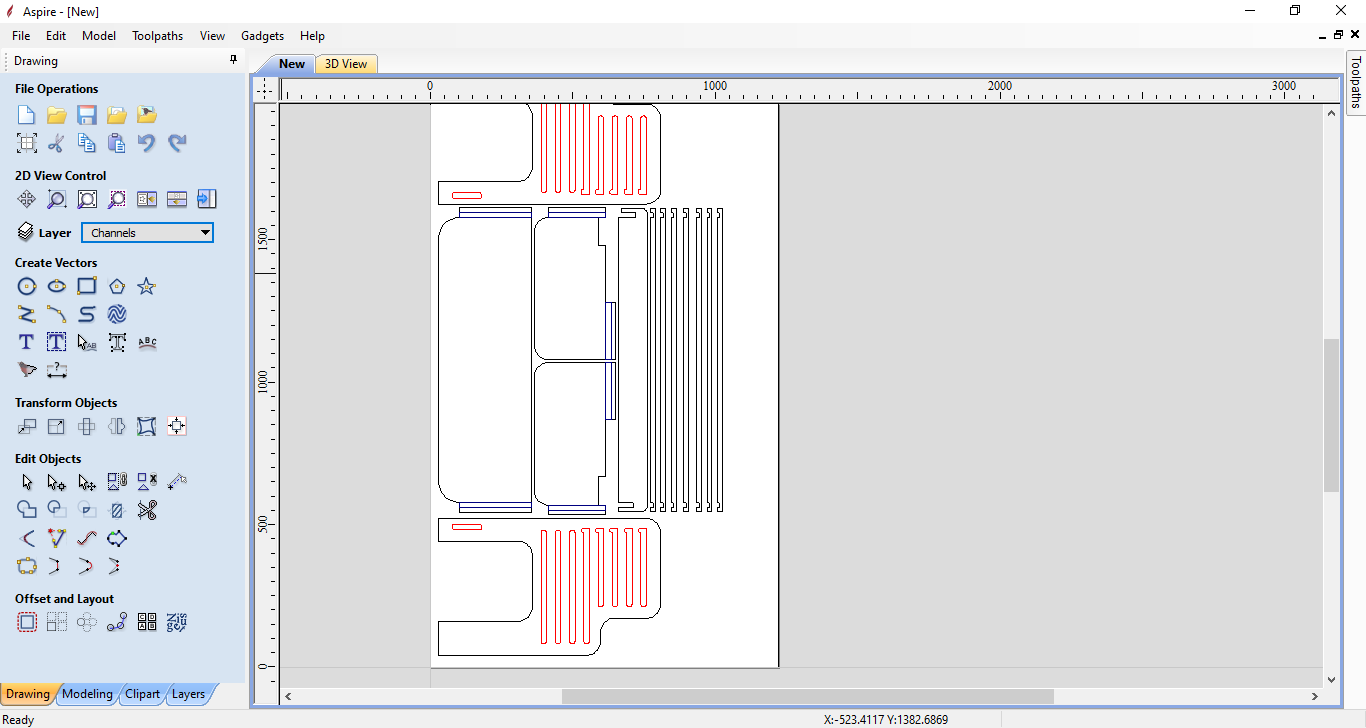
Each of these color lines should be configured with its corresponding toolpath operation. The black lines should be cut from outside to the end of the stock thickness, and the red lines should be cut from inside. The blue lines should be cut from inside, as well, but halfway of the stock thickness.
Note that I used a 6mm endmill.
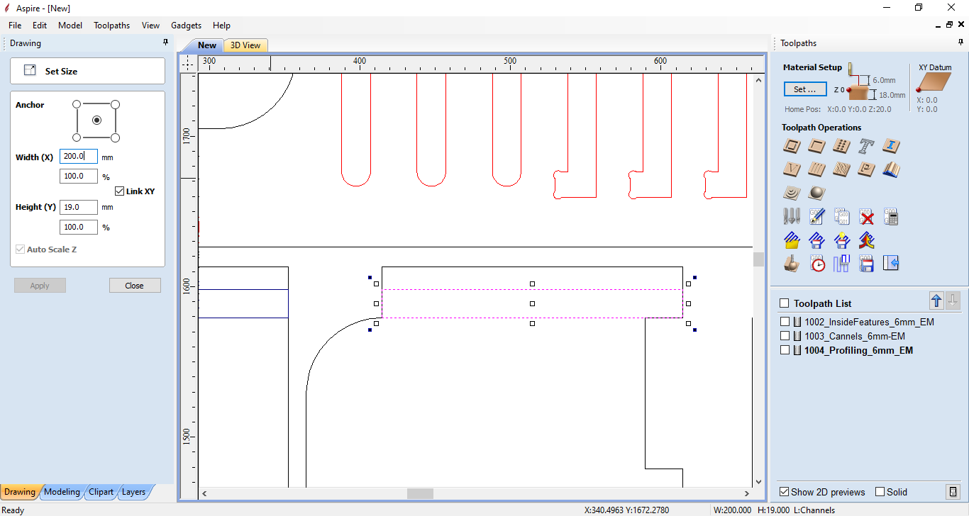
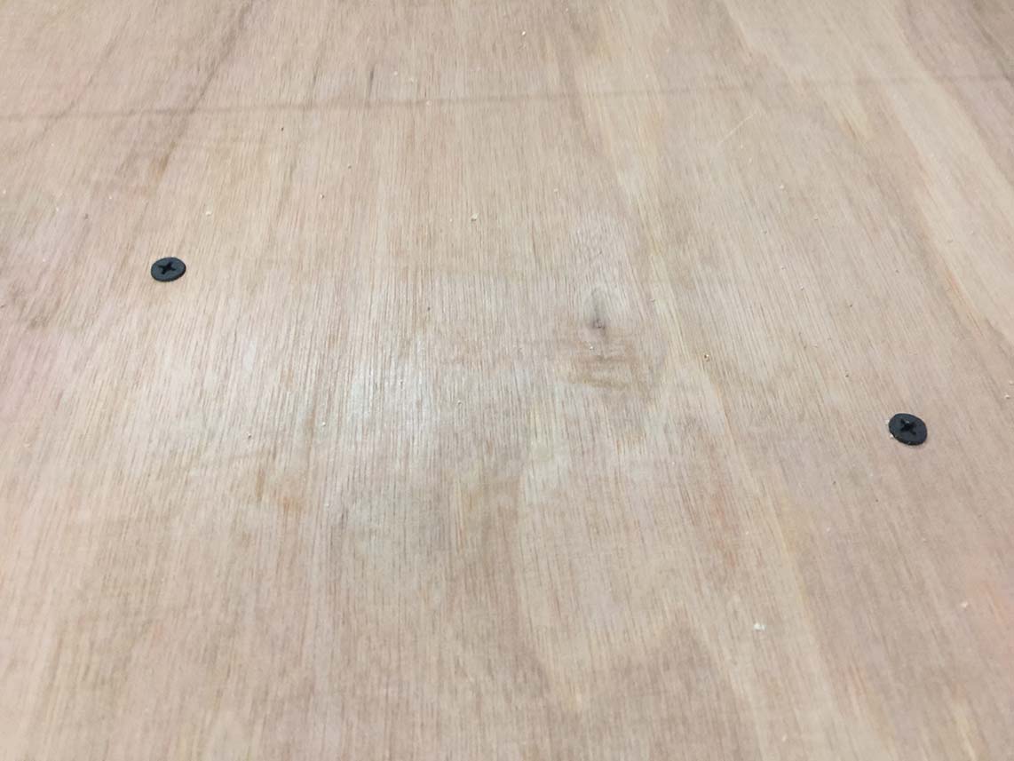
Another important operation to add before exporting- is to have some holes for the nails the should hold our wooden sheet to the bed sheet. This should be performed at the beginning of out job- with a 3mm drill bit.
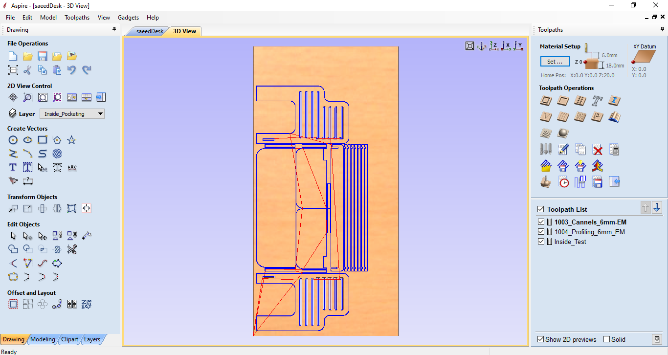
Now we are ready to export the files and go to the machine.
Machining
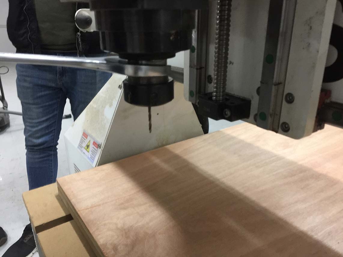
Here we go to our noisy machine. We need first to lay a wooden sheet on the bed.
I then installed a 3mm drill bit to the collet, and executed the first operation; which was plunging through the wood to make some holes for the nails.
I fastened the holding nails in place using a hand screwdriver.
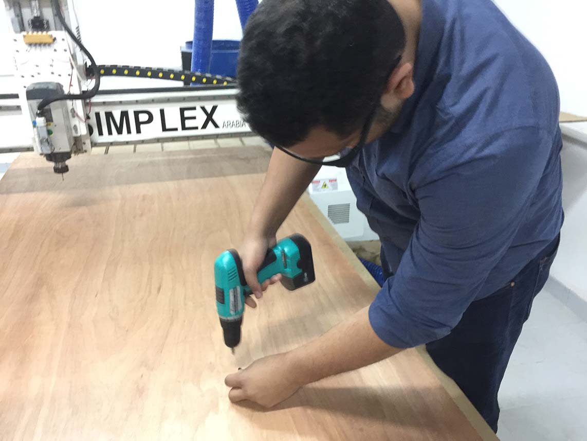

Nicely done : )
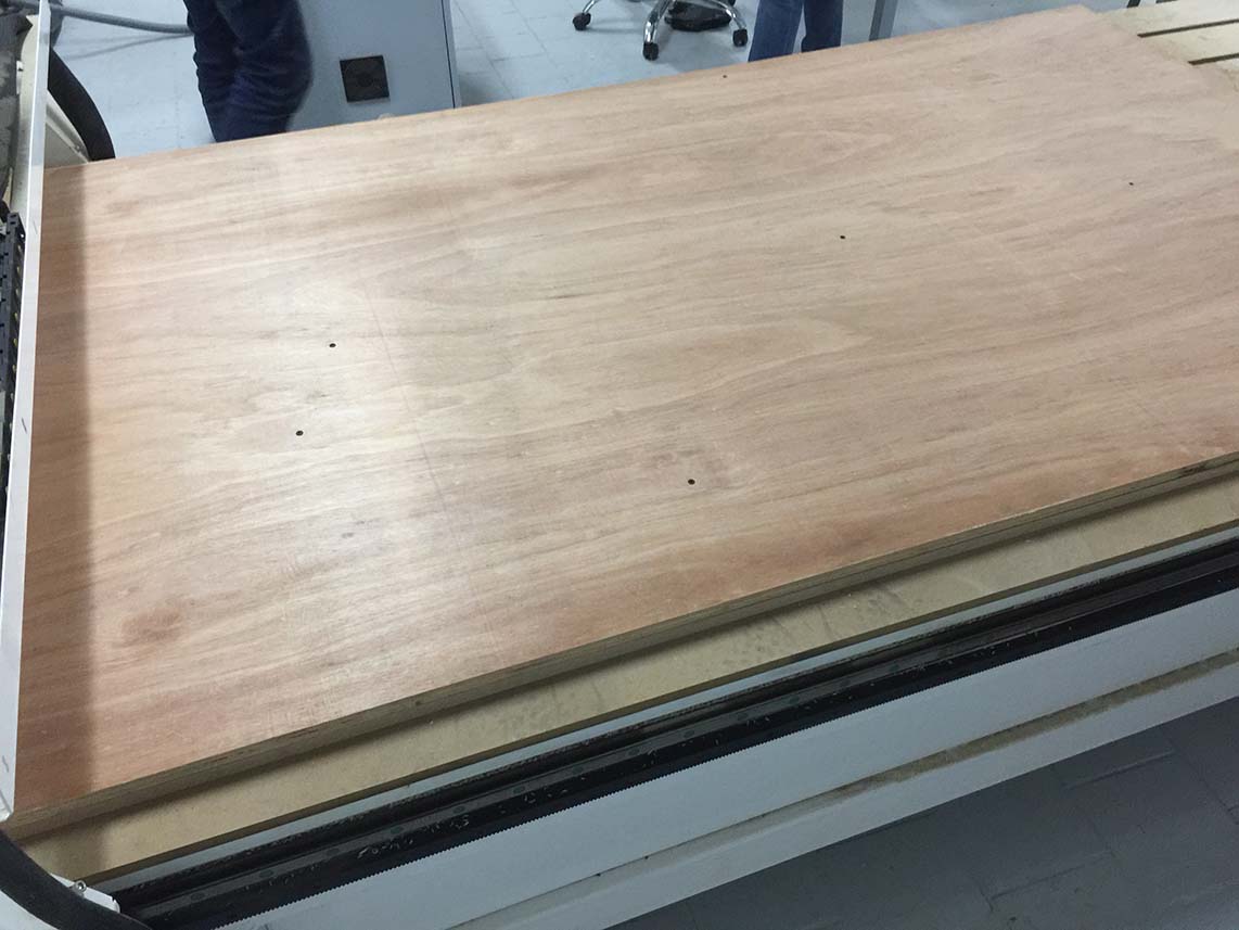
I then re-installed the 6mm endmill, which we had tested for runout before.
Here we finally go. Starting with internal cuts and pockets (red lines), then the profiling (blue lines), and finally cut the outline (black lines).
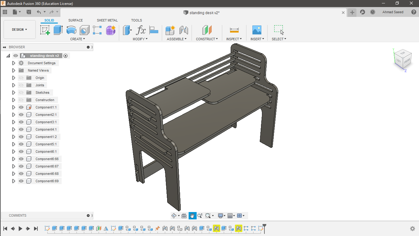
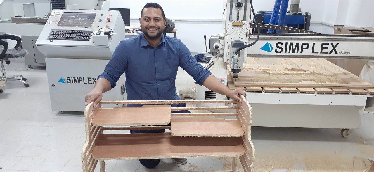
Luckily, the desk came out nice and clean from the first time.
I was really happy to have my first ever CNC cut very successful :D
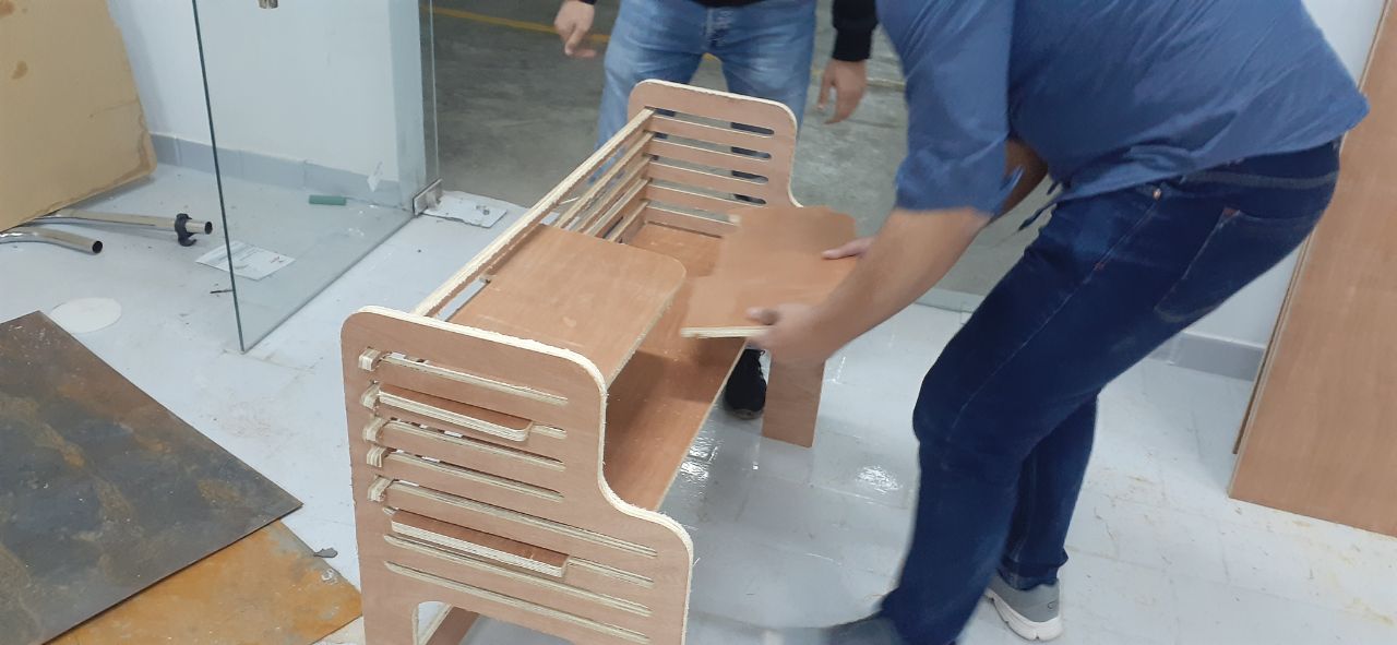
Let's do some testing :D :D
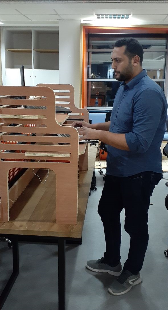
The overall process was easy (Luckily).. but nothing is perfect as we all know. I didn't get the chance to work on the new desk; since we left everything in the office and went for the lockdown the day after I finished the job : )))
Downloads