- Group Assignment:
- Characterize the design rules for your PCB production process
- Individual Assignment
- Make an in-circuit programmer by milling and stuffing the PCB,
test it, then optionally try other PCB processes
- Make an in-circuit programmer by milling and stuffing the PCB,
- Link to the group assignment page
- Document how I made (mill, stuff, solder) the board
- Document that my board is functional
- Explain any problems and how I fixed them
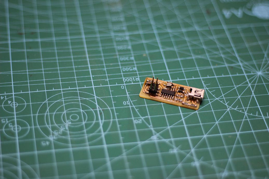
- Include a ‘hero shot’ of my board

Modela MDX-20 Fab Modules USBasp
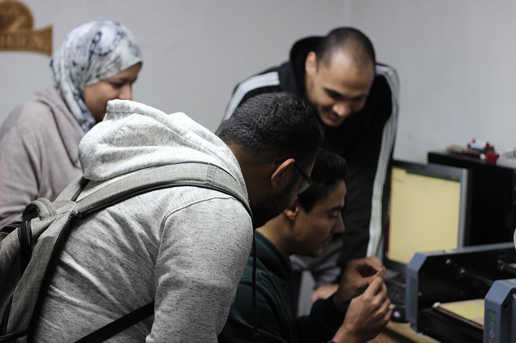
Group Assignment
The group assignment was to characterize the deisgn rules for our machine. Our setup was:
- Roland MDX-20
- 1/32'' endmill
- 1/64'' endmill
- 6"x8" Single-sided FR1
- Sketch tape
- Double-sided tape
- Vacuum cleaner
- Traces and Interior of the test files
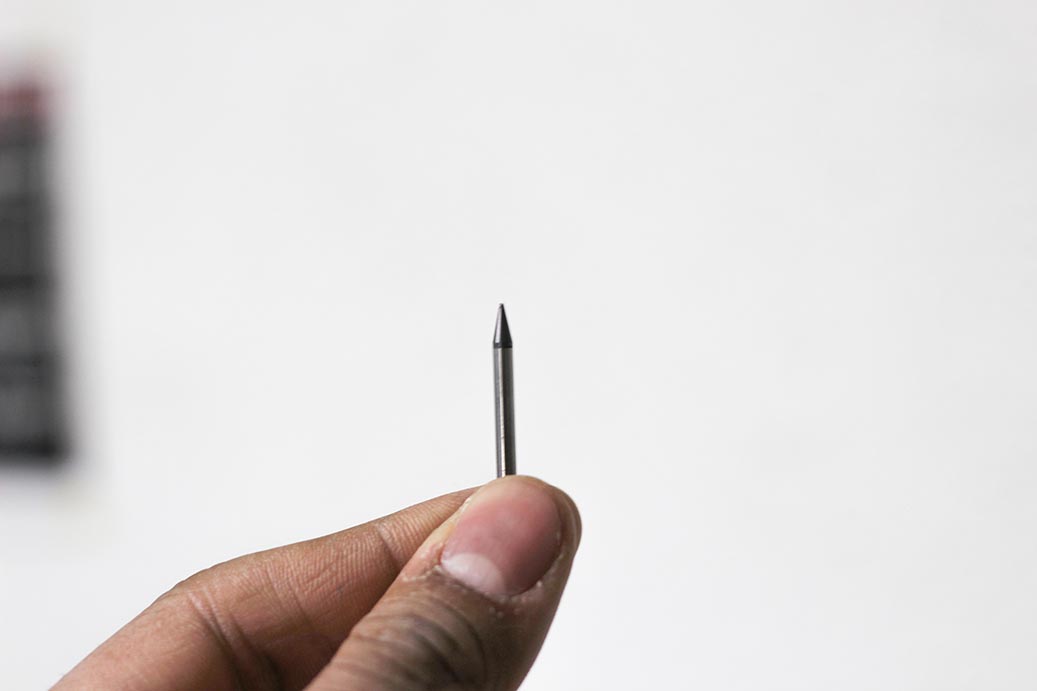
The (1/64'') endmill was dropped by accident. The poor thing got broken so easily. It is very delicate. We had to replace it.
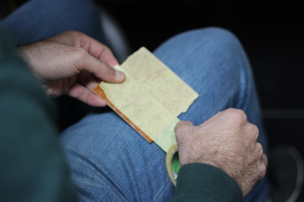
We started by installing the sketch tape onto the machine bed and the copper sheet. This would allow us put double-face tape without suffering from being sticky to the bed nor the PCB.
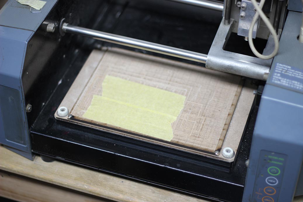
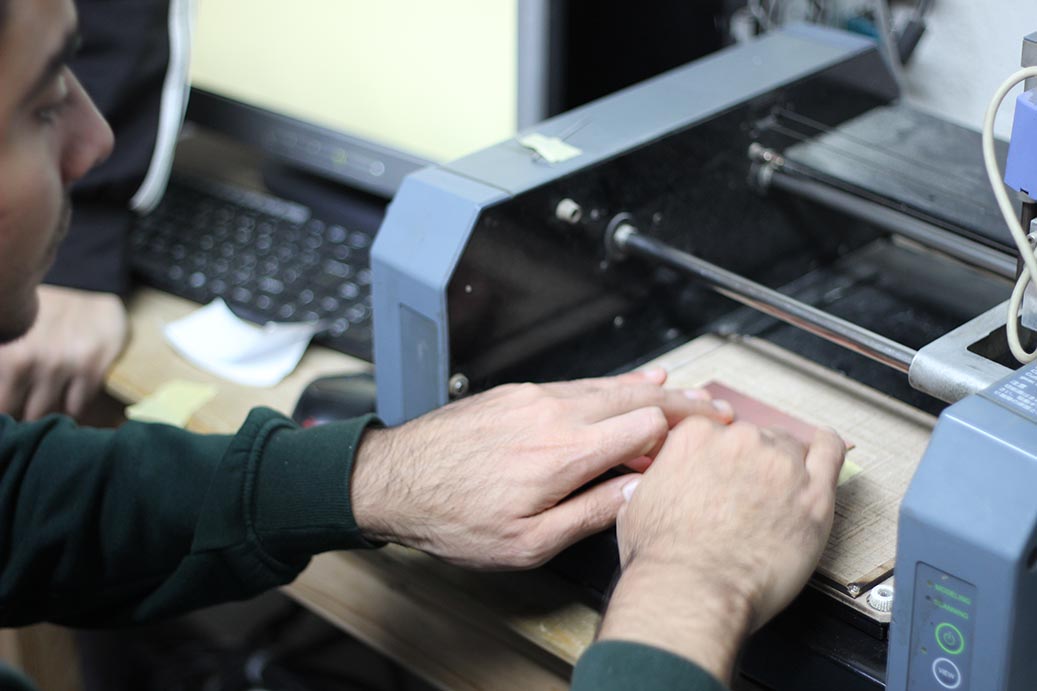
We followed the fabmodules steps, mentioned later, in order to mill our test file.
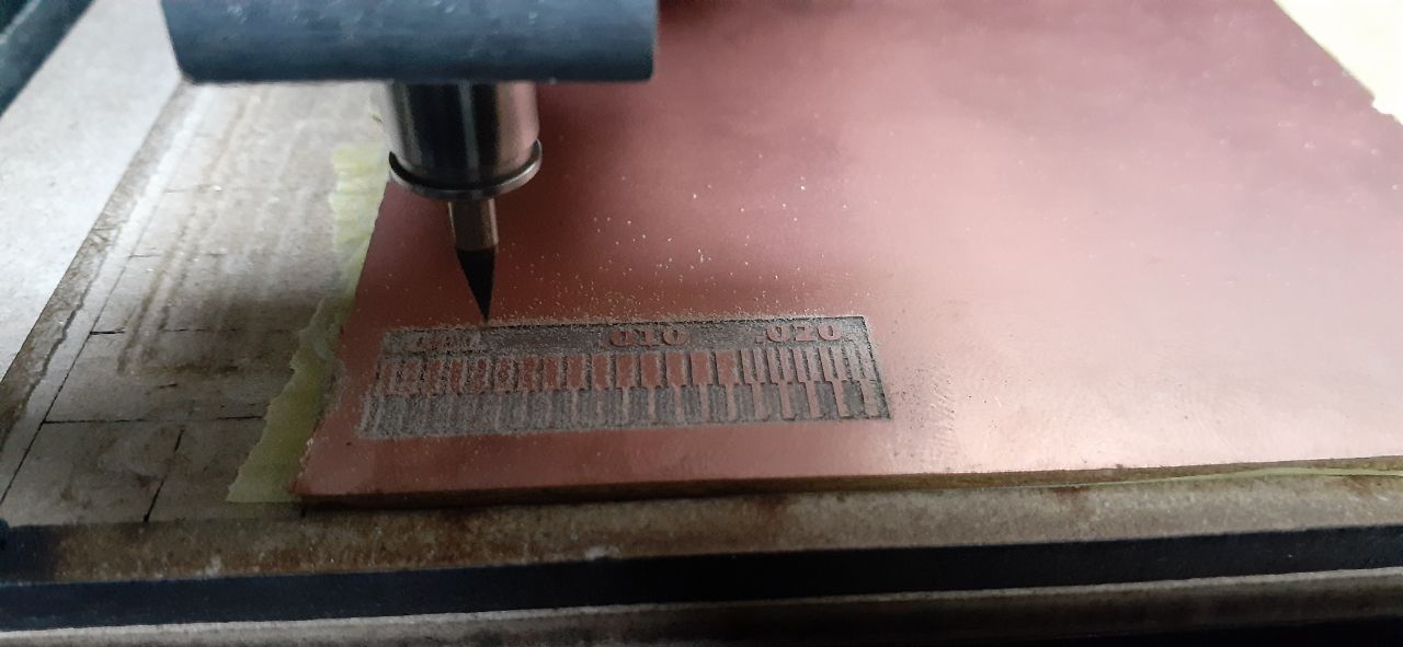
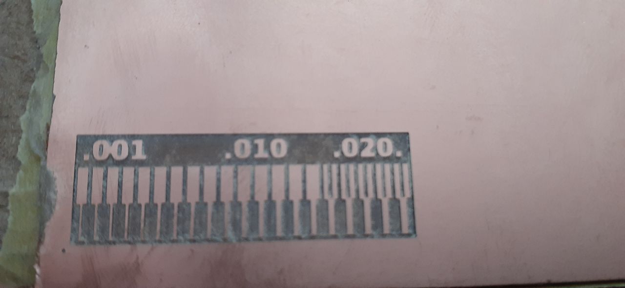
We found out that the thinnest trace could be milled is 0.001'' (0.0254 mm) and the smallest clearance between tracess could of course as small as the endmill diamater (0.4mm).
Valentin's ISP
I decided to make an ATtiny44 based ISP; because we had a lot of them in our inventory.
I started by donwnloading Valentin's circuit layout and cutout and loaded them to the Fab Modules.
The first thing to do is to install the (1/64'') endmill to the machine.
- Power-on the machine. It would start in the view mode.
- Install the endmill by lossing and fastening the two little screws with a hex key.
- Exit the view mode by pressing the view button on the machine.
- Use the fabmodules to move the endmill a little bit above the origin point- unscrew the endmill to make it touch the copper sheet, then screw it back. The operation of the fabmodules is described next.
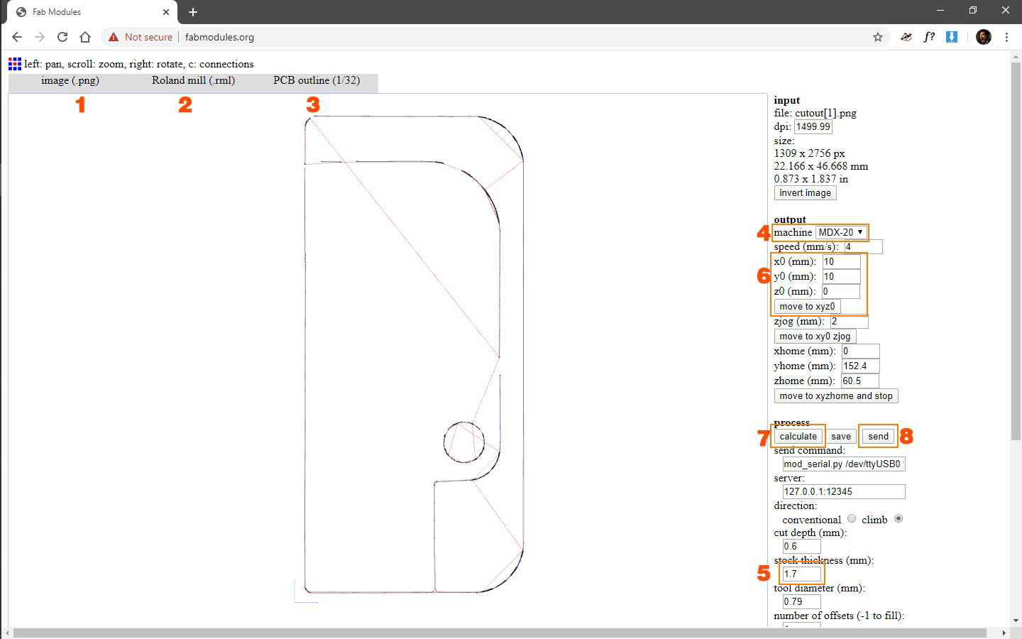
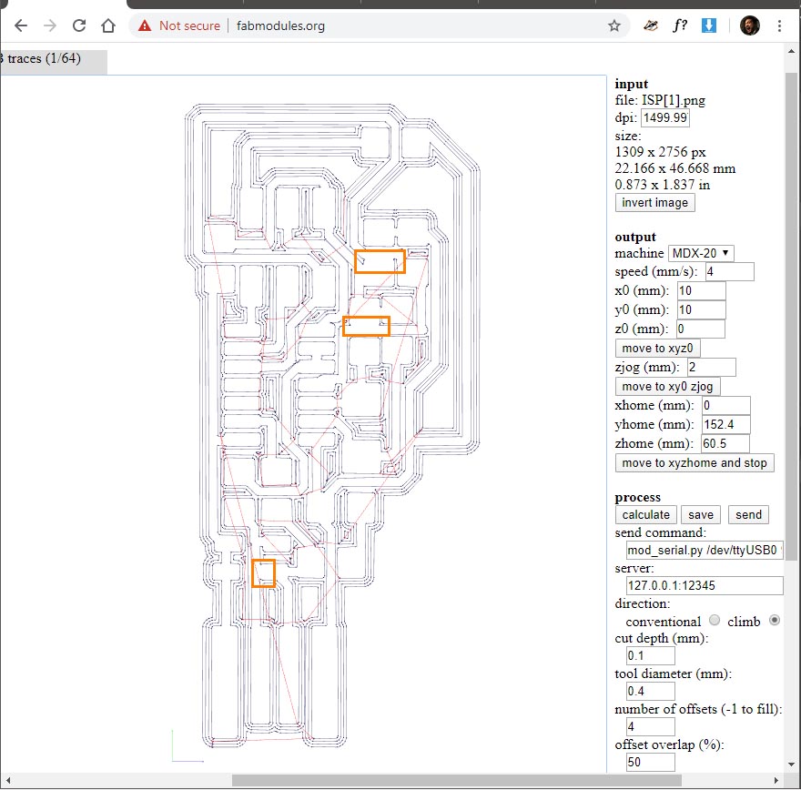
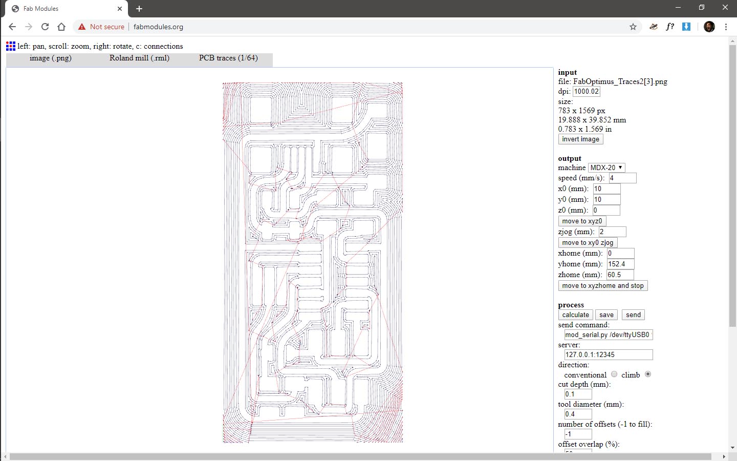
Preparing a circuit for milling is pretty straightforward, you just have to follow a set of steps:
- You select the format of your design file. It's png in our case.
- You select the output you want. It's .rml if you'r using a roland machine.
- Select the operation you want to do. You should start by milling the traces first.
- Now, select the model of the machine.
- Set the number of offsets you want your endmill remove around the traces. The larger the number, the more copper to remove. If you entered -1, the machine would remove all the copper except for the design traces and pads.
- Move the machine and set the point you want to start from. It should be the bottom-left point.
- Clicking Calculate will prepare the machine instructions for milling the traces.
- When the instructions are ready; just send them to the machine.

Now comes the most satisfying part: cutting the PCB out of the copper sheet. This is done by following straightforward steps as well:
First, replace the (1/64'') endmill with the (1/32'').
- Select the format of your design file. It's png also.
- Select the output you want. It's .rml.
- Select the operation. It's PCB outline.
- Select the machine again.
- Make sure the thickness is right. You can just round the numbers up to the first decimal if you're confused.
- Move the machine to the same origin point. Make sure the endmill is touching the copper sheet.
- Click Calculate.
- Click Send. Now, we're done. Just wait.
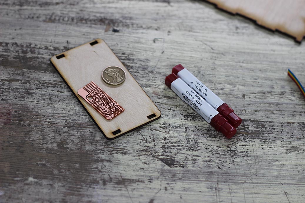
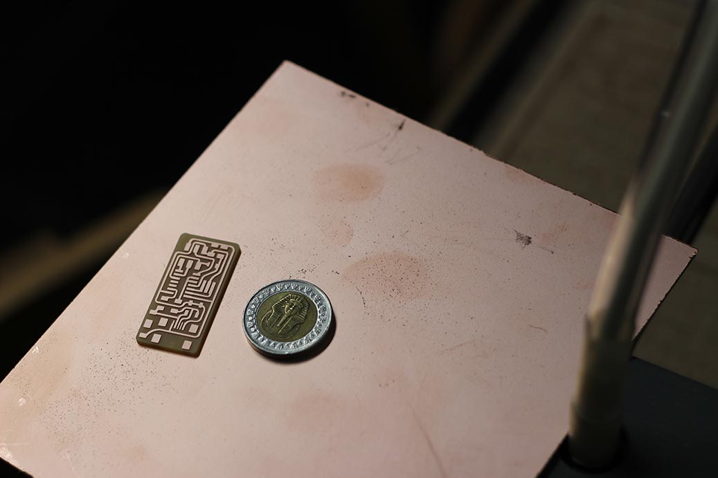
The PCB came out nice and clean. I used flux to give it a shiny pose in the picture.
The BOM for the ISP was:
| Part Number | Description | Quantity |
|---|---|---|
| ATTINY44A-SSU-ND | IC AVR MCU 4K 10MHZ 8SOIC- | 1 |
| 609-5161-1-ND | 6 Positions Header Connector 0.100" SMD | 1 |
| 644-1039-1-ND | CRYSTAL 20.000000 MHZ 8PF SMD | 1 |
| 311-1152-1-ND | CAP CER 18PF 50V C0G/NPO 1206 | 2 |
| 399-4674-1-ND | CAP CERAMIC .1UF 250V X7R 1206 | 1 |
| 311-10.0KFRCT-ND | RES 10.0K OHM 1-4W 1% 1206 SMD | 1 |
| 311-1.00KFRCT-ND | RES 1.00K OHM 1-4W 1% 1206 SMD | 1 |
| 311-100FRCT-ND | RES 100 OHM 1-4W 1% 1206 SMD | 1 |
| 311-499FRCT-ND | RES 499 OHM 1-4W 1% 1206 SMD | 1 |
| 311-0.0ERCT-ND | RES 0.0 OHM 1-4W 1% 1206 SMD | 2 |
| BZT52C3V3-FDICT-ND | DIODE ZENER 500MW 3.3V SOD123 | 2 |
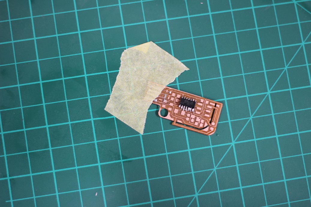
The next thing to do is to stuff the PCB with the components. I used tape to fix the PCB to the table. Then started stuffing inside out.

After I finished, I tried programming the PCB using USBasp but It didn't work. I made another one but the error repeated!!
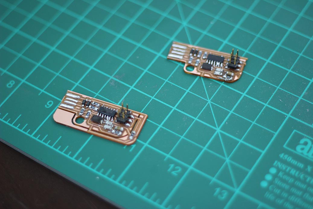
I wasted long time trying; till I figured out the problem. It was the design it self. The PCB can't be milled using a 0.4mm end mill. The fabmodules just merged traces together to come over the calculations.
I was really disappointed and didn't want to re-edit the design. Instead, I decided to just move on and try another deisgn.
FabOptimus
I decided to go for Ali's FabOptimus ISP. We didn't have 1.5K ohn resistors in the inventory, so I went to the Design Files (R_pullup=1K+0.5K). I downloaded the layout and the outline, and loaded them the same way to the fabmodules.
The only change is that I set the number of offsets to -1 so that the PCB would look pretty.
I followed the same steps and got my good-looking PCB.
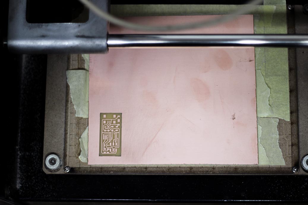
One more nice and clean PCB.
Here are the parts I used in stuffing the PCB.
| Part Number | Description | Quantity |
|---|---|---|
| ATTINY44A-SSU-ND | IC AVR MCU 4K 10MHZ 8SOIC- | 1 |
| 609-5161-1-ND | 6 Positions Header Connector 0.100" SMD | 1 |
| H2961CT-ND | CONN RECEPT MINI USB2.0 5POS | 1 |
| XC1109CT-ND | CER RESONATOR 20.00MHZ SMD | 1 |
| 445-1423-1-ND | CAP CER 1UF 50V X7R 10% 1206- | 1 |
| 311-10.0KFRCT-ND | RES 10.0K OHM 1-4W 1% 1206 SMD | 1 |
| 311-1.00KFRCT-ND | RES 1.00K OHM 1-4W 1% 1206 SMD | 1 |
| 311-100FRCT-ND | RES 100 OHM 1-4W 1% 1206 SMD | 2 |
| 311-499FRCT-ND | RES 499 OHM 1-4W 1% 1206 SMD | 1 |
| 311-0.0ERCT-ND | RES 0.0 OHM 1-4W 1% 1206 SMD | 1 |
| BZT52C3V3-FDICT-ND | DIODE ZENER 500MW 3.3V SOD123 | 2 |
I'd also done the same steps stuffing the PCB. Beginning from using tape to fix it to the table, then started from insde components- out.
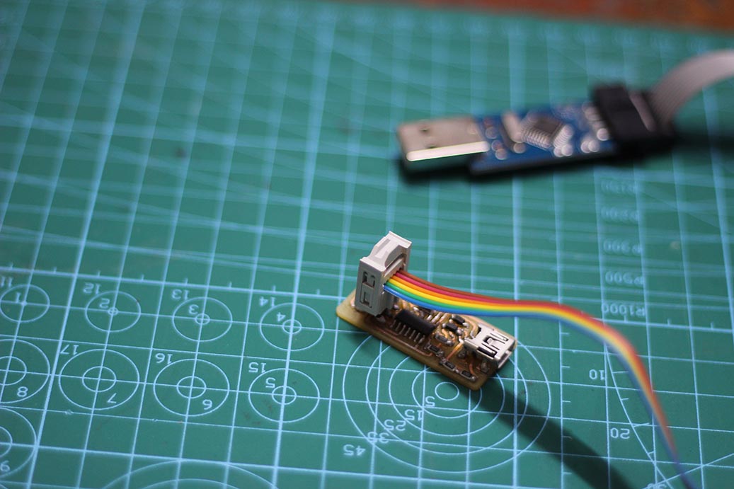
I had the USBasp programmer. The problem is the USBasp had 10-pin ISP header, but the programmer has the 6-pin header.
I had to connect the two headers using jumper wires.
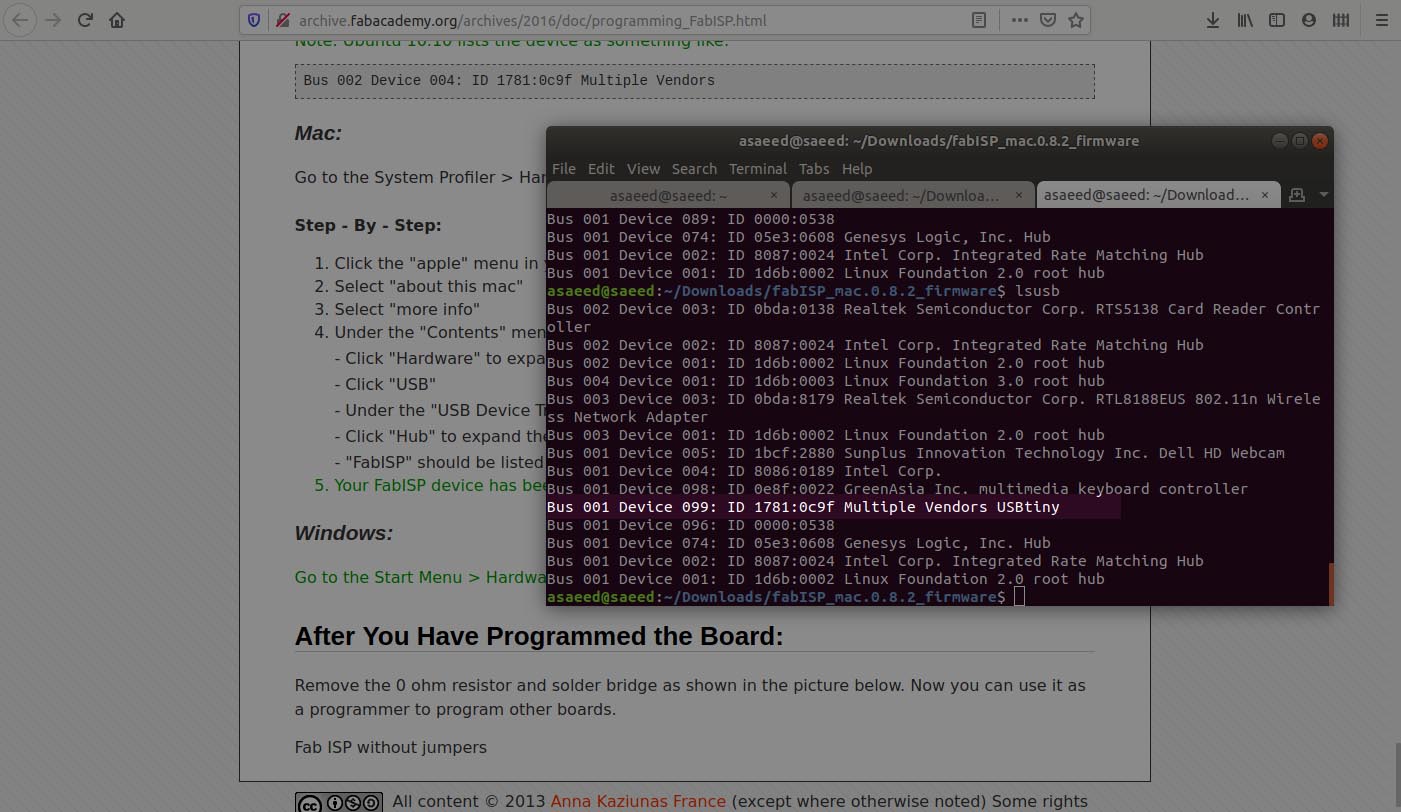
The windows WSL couldn't detect the USBasp. I found out that it doesn't support USB devices, so I moved to an Unbuntu Machine.
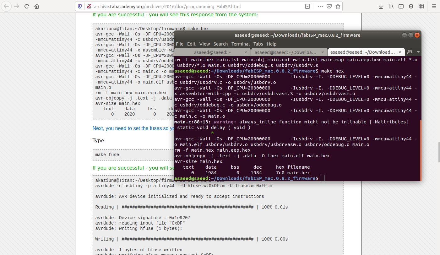
I downloaded and unzipped the firmware and followed the steps in the programming tutorial.
sudo apt-get install flex byacc bison gcc libusb-dev avrdudesudo apt-get install gcc-avrsudo apt-get install avr-libcsudo apt-get install libc6-devcd ~/Desktopcd fabISP_mac.0.8.2_firmwaremake cleanmake hexmake fusemake program

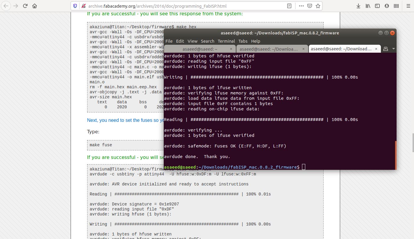
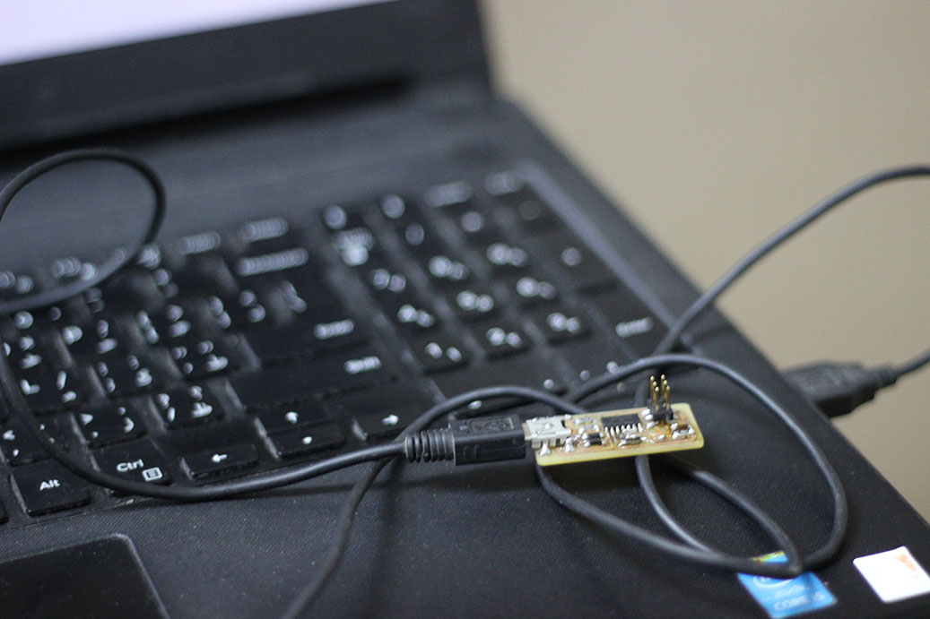
Everything worked properly. I removed the 0 ohm resistor by heating it using the soldering iron.
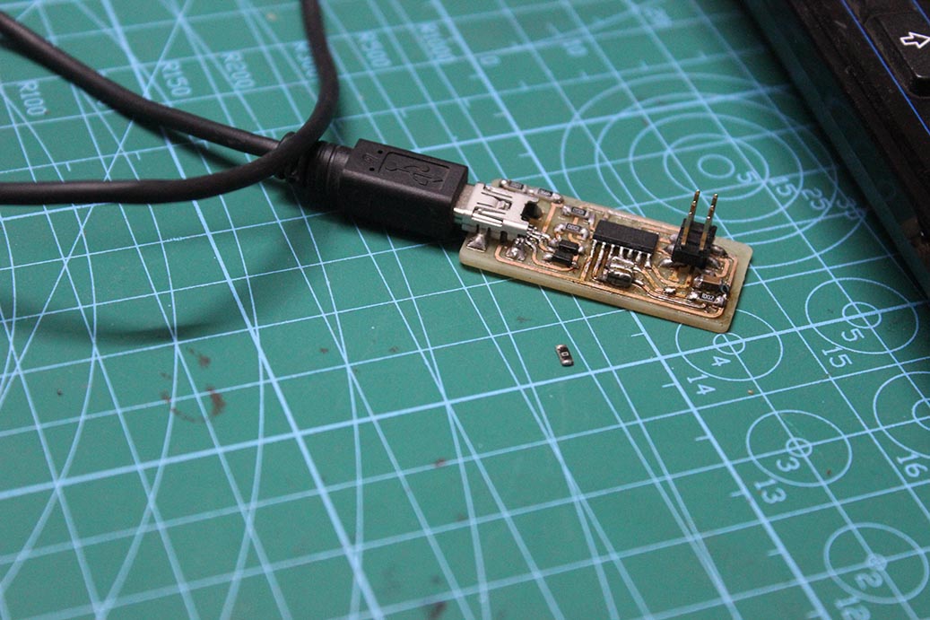
I connected the device to the USB and it worked on both Ubuntu and Windows.