Computer Controlled Cutting
This week I worked on the knife "vinyl" cutter and the laser cutter of the Fablab.
We worked together with Leon on the caracterization of the laser cutter and tried to cut some copper foil on the knife "vinyl" cutter.
The one we have access to is a Roland CAMM-1 GS-24 and we tried to cut a foil of fine copper to see if it could be used for rapid prototyping PCBs.
It was harder than it seems and the first results were a disaster. The foil of copper was more "ripped" than properly cut.
We then adjusted the deepness of the blade and varied the force of compression and the results were better.
But when it came to peel it, we couldn't easily separate the unwanted parts from the needed ones.
We've been missing time to investigate more, but we think that fine tuning both force and speed could lead to success.
Our last results were more encouraging than the first one.
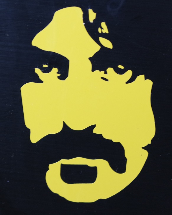
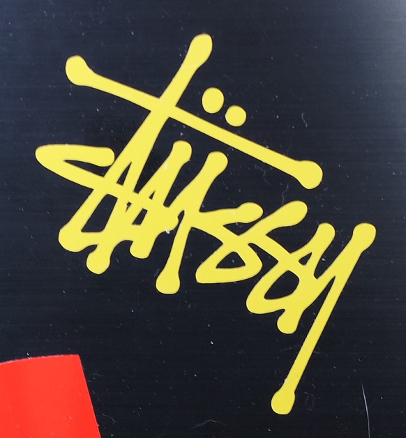
Cutting vinyl stickers was much easier and I successfuly cut several designs.
For a successful cut, the knife lenght and force has to be tuned to just cut the vinyl layer without cuting the underlaying paper.
Here are a few stickers :
The methods we used and our results can be seen here.
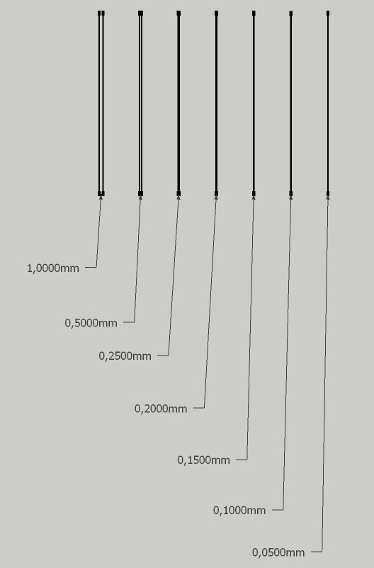
In order to caracterize the kerf we designed this cut pattern where 2 lines are getting closer and closer:
And this is the cut result showing that under 0.2mm there is no paper left between the lines. We can then consider our kerf to be 0.2mm:

I choosed to build an accessory that could engrave on cylindrical objects with a laser cutter.
It should allow to be assembled in multiple ways to deal with many kind of round objects (different shapes of glasses or mugs).
The design has to be parametric so I used FreeCAD.
Mostly I'd like to easily control a thickness parameter taking account for a kerf parameter.
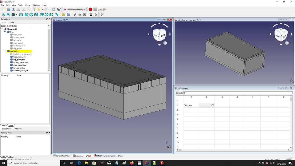
First I needed to get used to using FreeCAD. So I tried the LCinterlokings add-on, and after getting used to it, I managed to do this "test box":
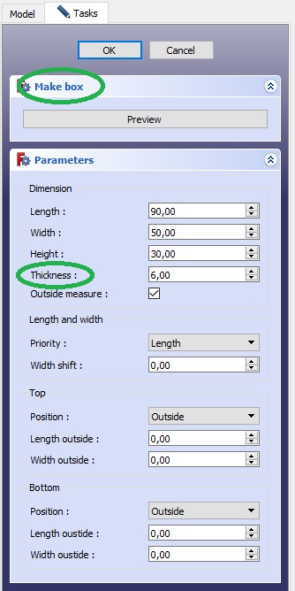
The thickness of the planes can be changed but has to be done in 2 places. First at the
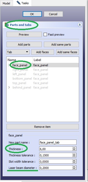
...then at the
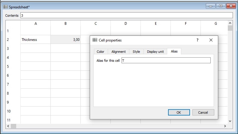
To be able to control the thickness in just one place, I switched to the Spreadsheet workbench to create a
But I didn't found how to tell
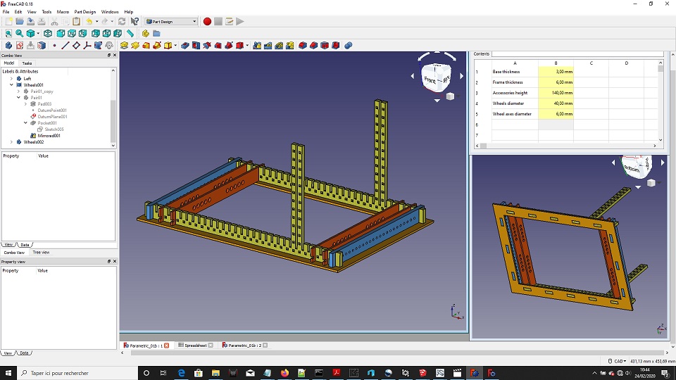
I designed all my parts from scratch and ended up with this parametric design where the thickness of the panels can be changed in a spreadsheet along with the diameter of the wheels and the lenght and diameter of the wheel axes:
Here is the FreeCAD file: Parametric_01b.FCStd
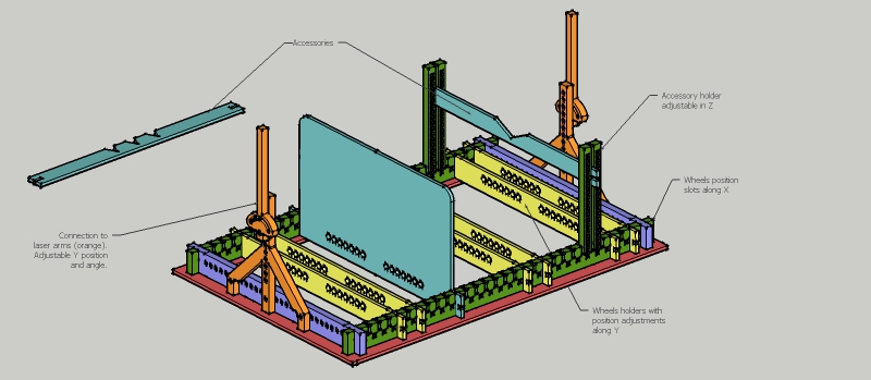
And here is another more complete model made in SketchUp:
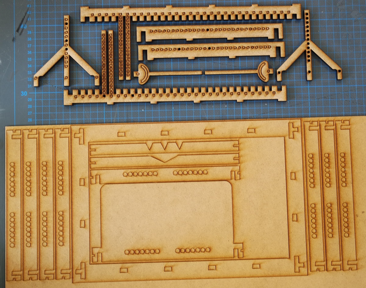
This photo shows the laser cutted parts:
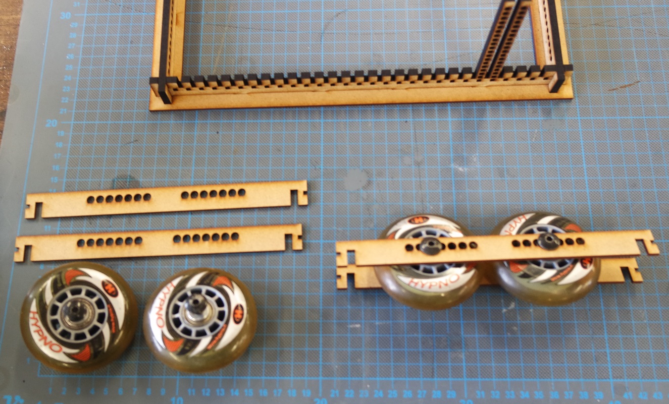
This one shows how the wheels from a roller skate are assembled:
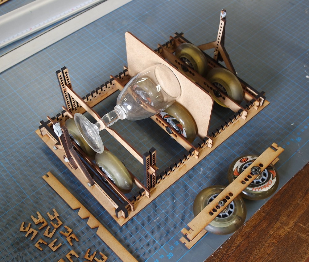
And here is the construction kit fully assembled:
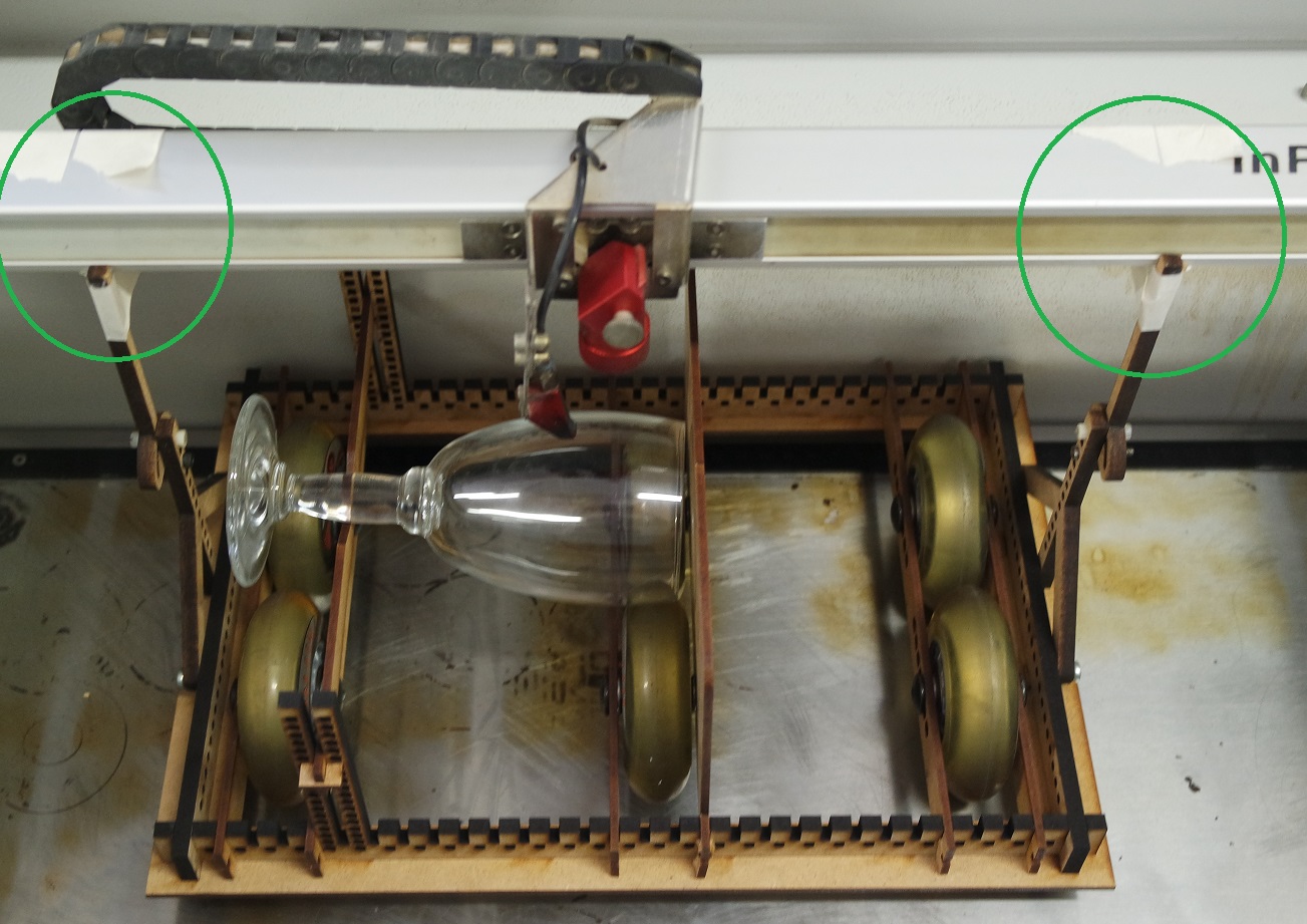
Fixing the arms of the kit to the laser gantry is a bit tricky and was done with the help of scotch tape (has to be improved):
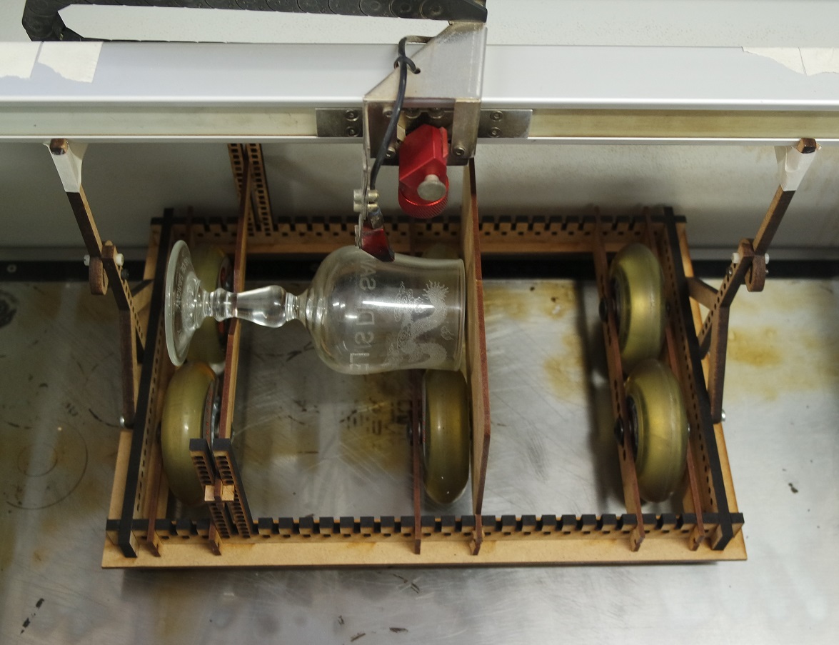
The focus is done where the engraved image should be.
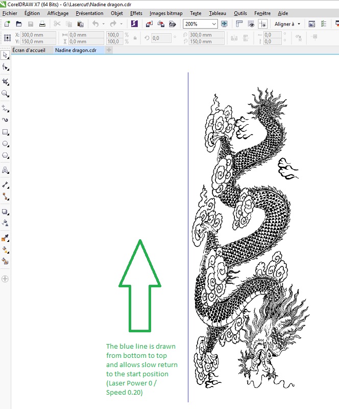
Here is a Coreldraw screenshot of the image to be engraved:
Here is a video showing the engraving process:
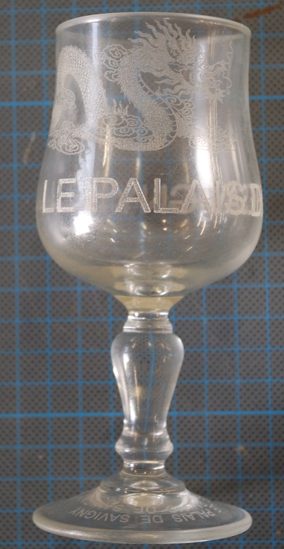
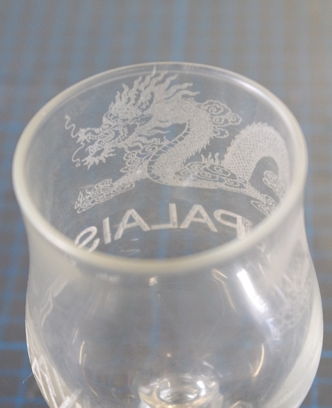
And this is the result of the engraving on a wine glass:
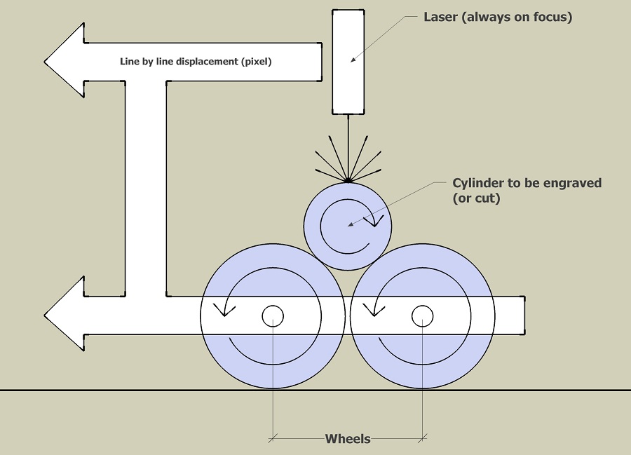
At each line change (Y+ axis) the laser gantry pushes the accessory by a small amount.
This displacement is transfered to the wheels and the object rotates by a corresponding small angle. This way the laser is always in focus at the top of the cylinder.
The way the vertical arms are fixed to the laser gantry also need to be improved.
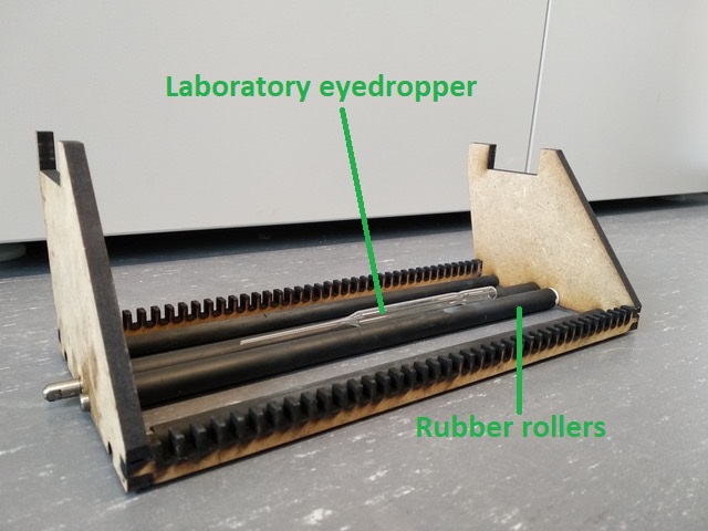
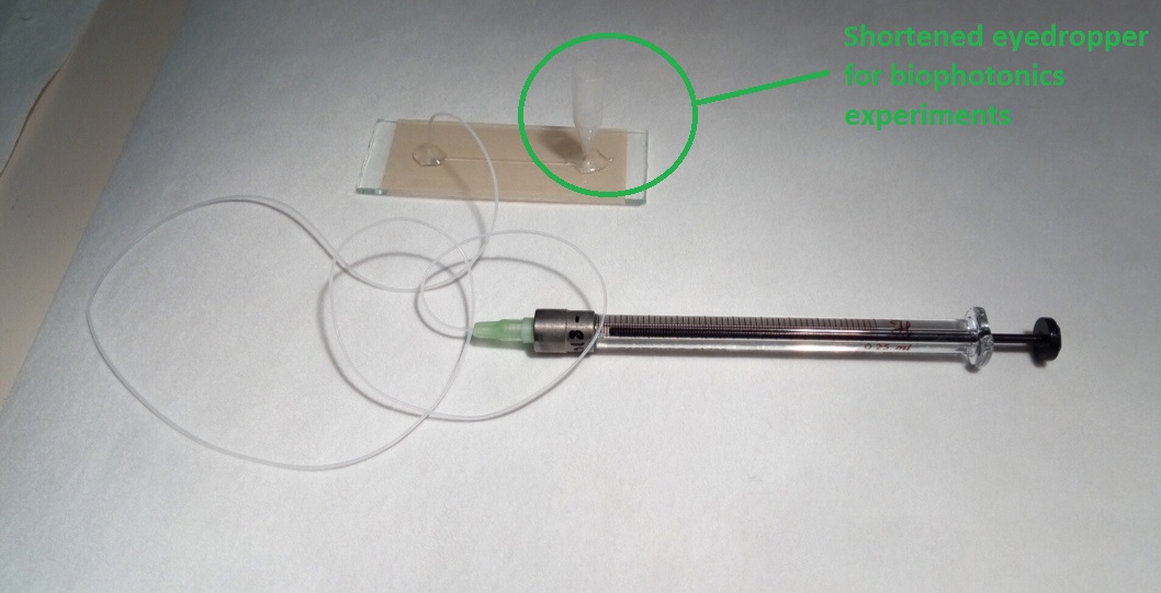
Recently a researcher of our school needed to find a way to shorten laboratory eyedroppers for her biophotonics experiments.
Thanks to the rotary stage it was possible but I decided to build a custom stage for just that need.
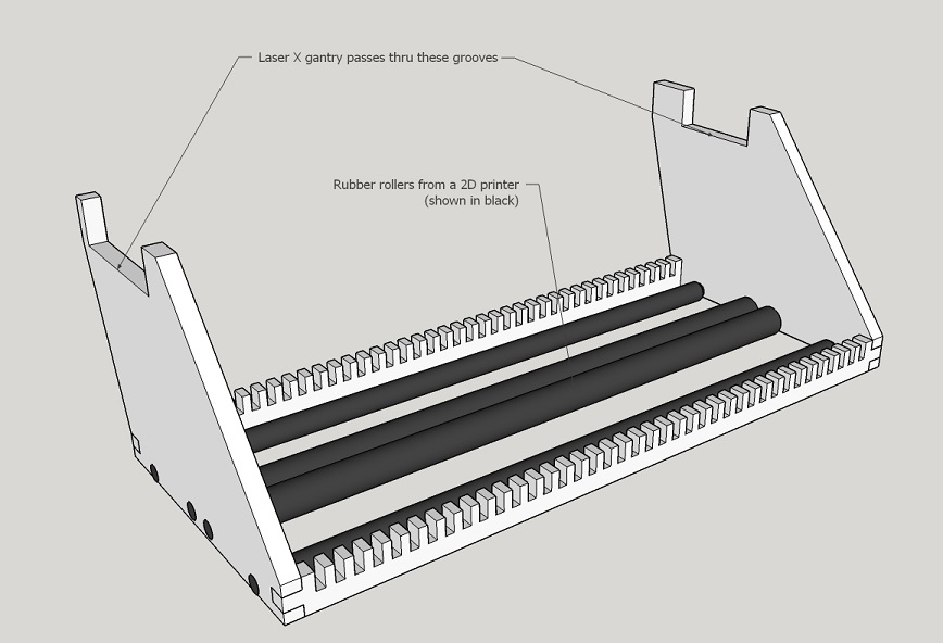
It works with rubber rollers found in old printers instead of using roller wheels, but the principle is exactly the same:
It made me realise that I designed it too small early in the design process so I corrected my CAD accordingly.
zappa_sticker.svg
stussy_sticker.svg
We worked together with Leon on the caracterization of the laser cutter and tried to cut some copper foil on the knife "vinyl" cutter.
The knife "vinyl" cutter
The vinyl cutter uses a blade to cut thru material by following a vector design.The one we have access to is a Roland CAMM-1 GS-24 and we tried to cut a foil of fine copper to see if it could be used for rapid prototyping PCBs.
It was harder than it seems and the first results were a disaster. The foil of copper was more "ripped" than properly cut.
We then adjusted the deepness of the blade and varied the force of compression and the results were better.
But when it came to peel it, we couldn't easily separate the unwanted parts from the needed ones.
We've been missing time to investigate more, but we think that fine tuning both force and speed could lead to success.
Our last results were more encouraging than the first one.
Cutting vinyl stickers was much easier and I successfuly cut several designs.
For a successful cut, the knife lenght and force has to be tuned to just cut the vinyl layer without cuting the underlaying paper.
Here are a few stickers :
The laser cutter
At the lab we have access to a (Epilog "Fusion M2").Group assignment : caracterization of the machine
Our goal is to caracterize:- focus
- power
- speed
- rate
- kerf
- joint clearance
The methods we used and our results can be seen here.
In order to caracterize the kerf we designed this cut pattern where 2 lines are getting closer and closer:
And this is the cut result showing that under 0.2mm there is no paper left between the lines. We can then consider our kerf to be 0.2mm:
Individual assignment
We were asked to design, lasercut, and document a parametric construction kit which can be assembled in multiple ways.I choosed to build an accessory that could engrave on cylindrical objects with a laser cutter.
It should allow to be assembled in multiple ways to deal with many kind of round objects (different shapes of glasses or mugs).
The design has to be parametric so I used FreeCAD.
Mostly I'd like to easily control a thickness parameter taking account for a kerf parameter.
First I needed to get used to using FreeCAD. So I tried the LCinterlokings add-on, and after getting used to it, I managed to do this "test box":
The thickness of the planes can be changed but has to be done in 2 places. First at the
Box level...then at the
Multijoin face_panel_tab menu level (where you also find the kerf value).To be able to control the thickness in just one place, I switched to the Spreadsheet workbench to create a
Thickness variable with alias T.But I didn't found how to tell
Box and Multijoin face_panel_tab to use T as their thickness respectively.4th axis rotary stage
I'd like to try making a 4th axis rotary stage for the laser cutter.I designed all my parts from scratch and ended up with this parametric design where the thickness of the panels can be changed in a spreadsheet along with the diameter of the wheels and the lenght and diameter of the wheel axes:
Here is the FreeCAD file: Parametric_01b.FCStd
And here is another more complete model made in SketchUp:
This photo shows the laser cutted parts:
This one shows how the wheels from a roller skate are assembled:
And here is the construction kit fully assembled:
Fixing the arms of the kit to the laser gantry is a bit tricky and was done with the help of scotch tape (has to be improved):
The focus is done where the engraved image should be.
Here is a Coreldraw screenshot of the image to be engraved:
Here is a video showing the engraving process:
And this is the result of the engraving on a wine glass:
How the rotating accessory works
In raster engraving mode the laser cutter works line by line rather than following a cut path.At each line change (Y+ axis) the laser gantry pushes the accessory by a small amount.
This displacement is transfered to the wheels and the object rotates by a corresponding small angle. This way the laser is always in focus at the top of the cylinder.
Improvements
The prototype takes a lot of Z space thus reducing the diameter of the objects that can be engraved. By using smaller wheels it could allow bigger objects to be engraved.The way the vertical arms are fixed to the laser gantry also need to be improved.
Recently a researcher of our school needed to find a way to shorten laboratory eyedroppers for her biophotonics experiments.
Thanks to the rotary stage it was possible but I decided to build a custom stage for just that need.
It works with rubber rollers found in old printers instead of using roller wheels, but the principle is exactly the same:
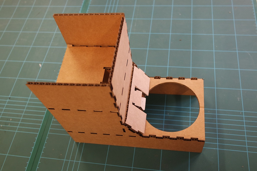
2021 CAD week
This year, as a continuing student, I used this week to lasercut a cardboard prototype for my project.It made me realise that I designed it too small early in the design process so I corrected my CAD accordingly.
Files for this week
feeder_V4_02.dxfzappa_sticker.svg
stussy_sticker.svg