
2021 project - Vinyl record cutting lathe
Introduction
This is my initial project description for 2021.
As a continuing student (I started my Fabacademy in 2020), I already planned a project last year.
But I have another project idea that might replace my initial one : a Vinyl record cutting lathe.
Inspiration and description
The idea emerged because I'm a vinyl record collector that have always dream of being able to "record" music on vinyl blank records.
Machines that are made to "record" music on vinyls are called Vinyl record cutting lathe.
It's basically a machine that "cuts" a groove in a plastic sheet (blank vinyl) that is spinned on a turntable at precise speed (RPM).
The continuous spiral groove is cut by an expensive diamond needle which is vibrating, driven by small sound devices (speakers).
How does it work?
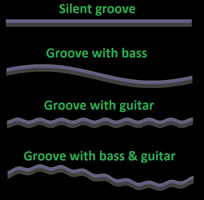
The sound to be engraved is transferred to a needle that vibrates while engraving the media.The result is a groove that reproduces the sound waves (frequencies). Here is a schematic showing different grooves seen from above:
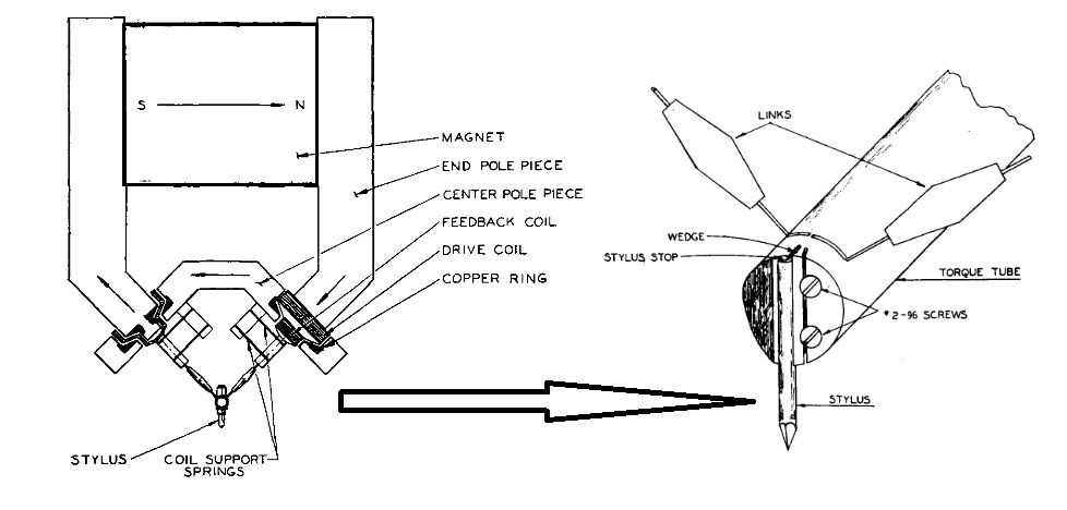
Here is a diagram of a cutting head and vibrating needle:
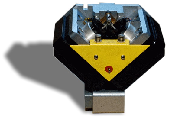
A professional cutting head and needle looks like this and are very expensive:
This is a very nice video explaining how a cutting head works by simulating the needle's vibrations with servo motors.
It's very well explained and helped me a lot at understanding the principles:
What about stereo?
The groove can be modulated either vertically or horizontally. And by combining both, two channels can be engraved in the groove (stereo).But because vibrating vertically is harder than horizontally, the cutter head system is turned 45° so both channels are engraved at 45° angle.
Here is a page with very good diagrams explaining it.
But the same website also explains why one should be carefull when engraving stereo signals...
And why high and loud trebles are not possible, and why sharp attacks and high trebles should be placed at the beginning of the vinyl (higher speed near the perimeter).
How long is the recording time?
It all depends on the width of the groove. The wider it is, smaller will be the recording time.The width of the groove depends on several factors:
- bass
- volume
- depth of groove
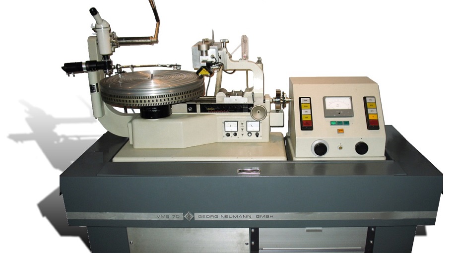
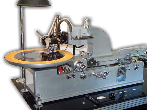
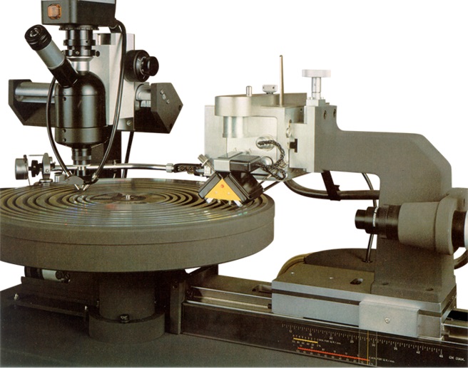
How does a vinyl cutting lathe looks like?
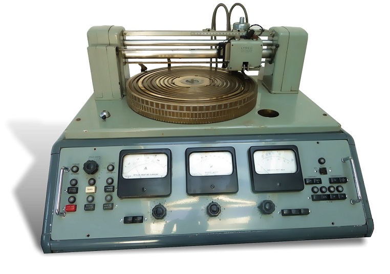
Most of the vinyl cutting lathes still in use nowadays are from the 50s, and there isn't many people left that know how to master them anymore.Cutting vinyls is considered as "a lost art"...
This is what these machines look like:
No progress since the 50s?
Since vinyls have made a big come back, even if they never really disappeared, more people are getting interested in the subject.We can start to find DIY projects by makers but it seems that none of them have been finished nor released:
And there's also a few commercial products for home use :
- Phonocut
- EZ record maker (designer)
- EZ record maker (commercial)
- DRC (commercial/abandonned)
- Carbon (a very complete design study)
Where to start?
One of the easiest way to start with when recording sound on vinyl seems to be the "embossing" technique.Instead of "cutting" the groove, it's being "engraved".
This can be achieve with a less cheaper needle that is mounted at a backward angle from the vinyl surface.
Instead of taking away some material like in the engraving process, it simply "pushes" the material in (embossing).
This technique is said to be easier to master but... at the price of a lower sound quality.
But all advices I could get from other makers are that I should first master embossing before going to the real cutting thing with an expensive and fragile diamond needle.
All in all, the machine I'm making should be able to adapt for real cutting when I will feel ready for it. Only the cutting head might change or maybe even just the needle.
Design considerations
One of the most important consideration to pay attention to is noise!It's important to make sure that as little noise as possible will be transmitted from the motors to the vibrating needle.
Unless it might be heard during playback of the record. If possible no noise at all should be transmitted.
For that reason it's important to use as less motors as possible and I will only use a single one to drive my engraving head along the X axis.
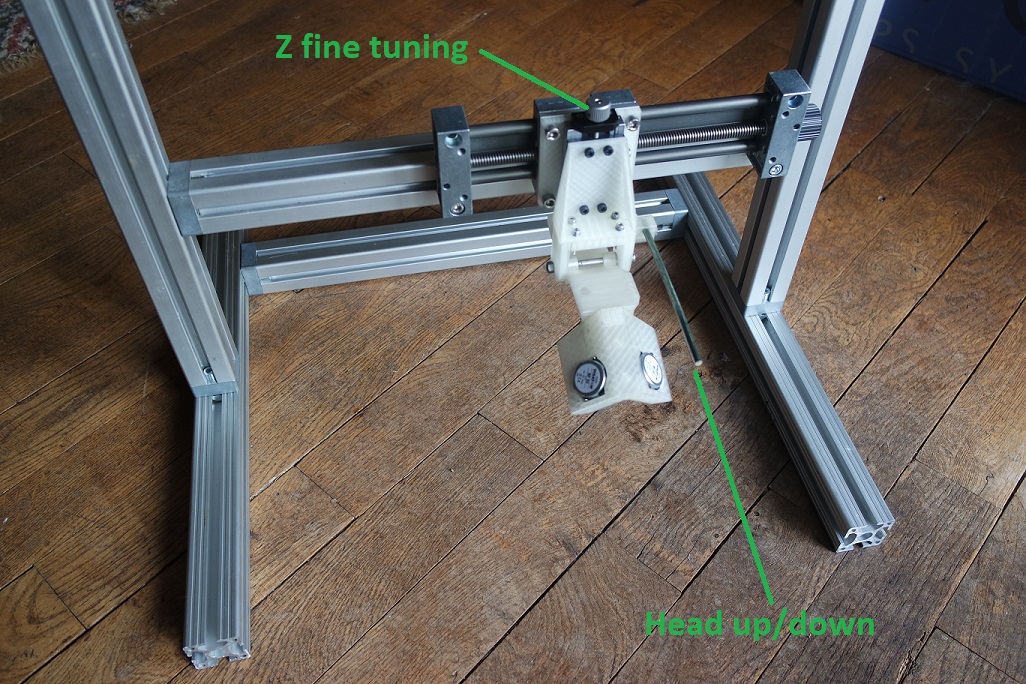
Lowering the engraving head onto the blank vinyl will be done manually like on most turntables.
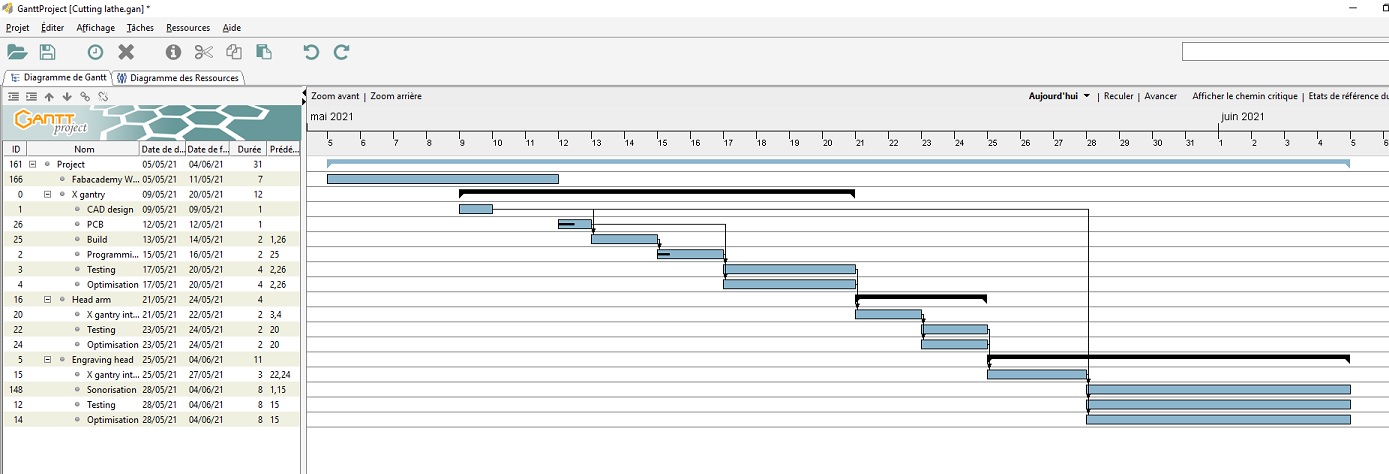
Early planification
I know... I'm late on my project and time is running short!Here is my Gantt diagram:
Early CAD prototyping
I started my 1st CAD design and printed a few parts to build the frame with 20x20mm aluminium extrusions.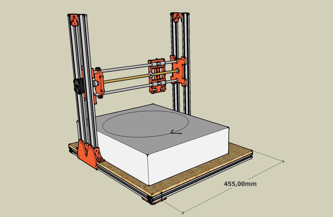
But I realised that it wasn't going to be strong and stiff enough and that it will take a lot of 3D printed parts, nuts, and bolts.
I remembered that I have some 40x40mm aluminium extrusions somewhere in my garage and found them back.
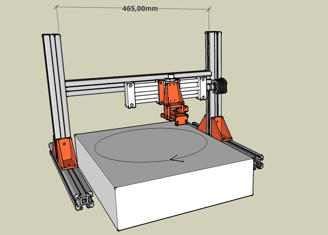
So I decided to build my frame with that instead and modified my design:
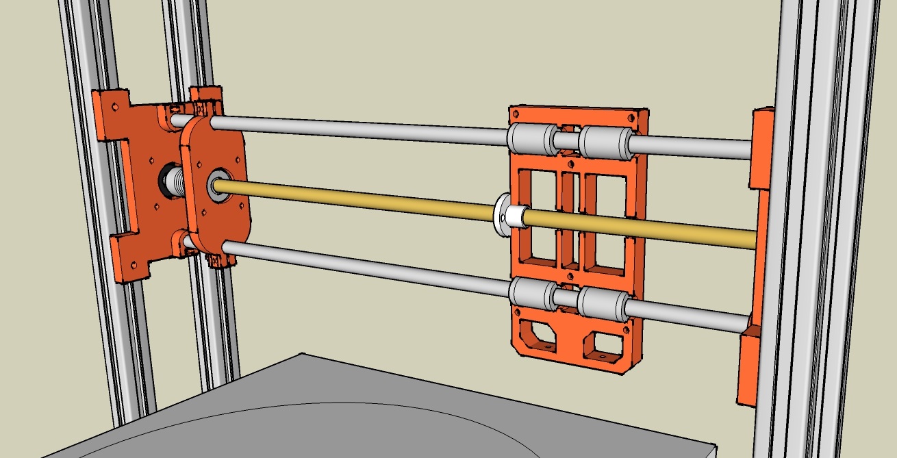
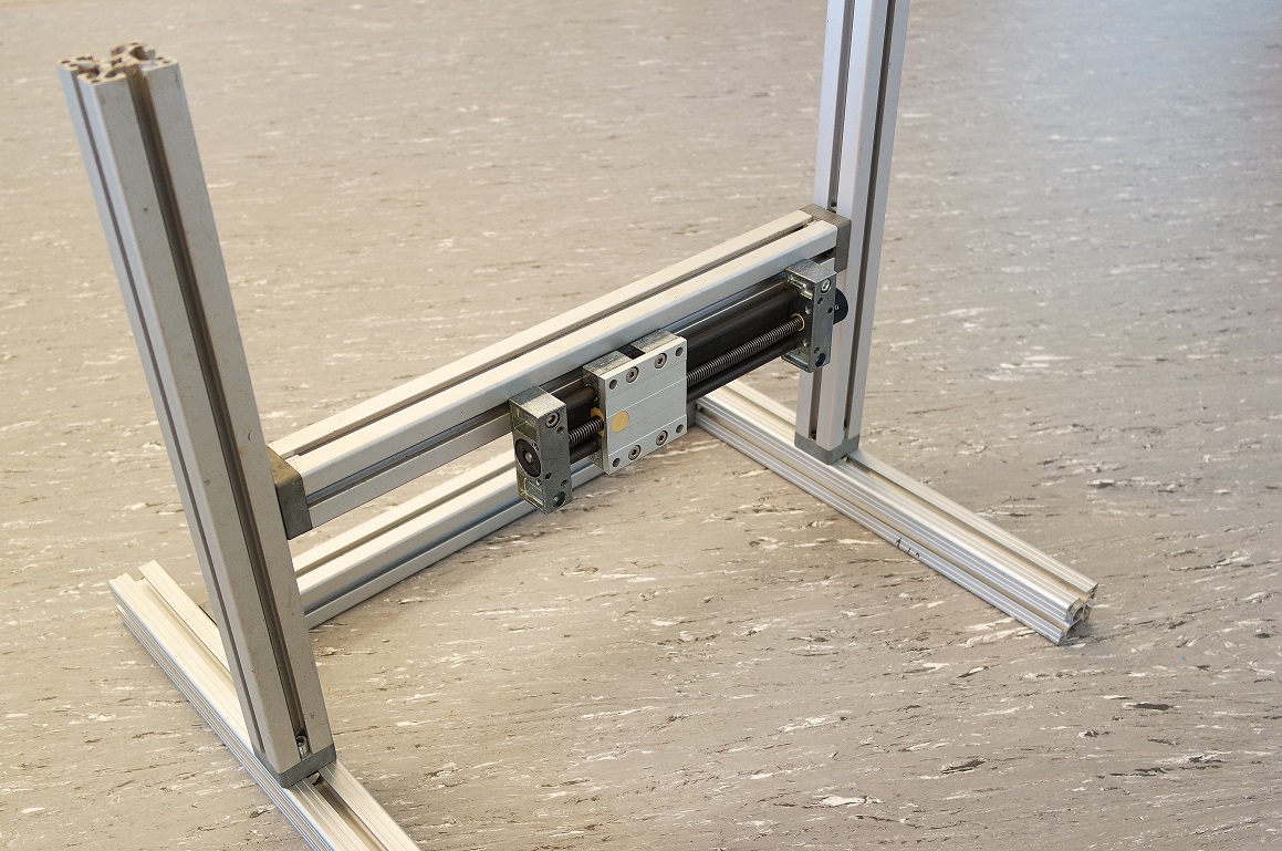
When searching what I had in stock at home, I also found back some nice one axis stages.
The long one can move along 150mm and will be my X axis while the small one will be used to fine tune the Z leveling of the engraving arm.
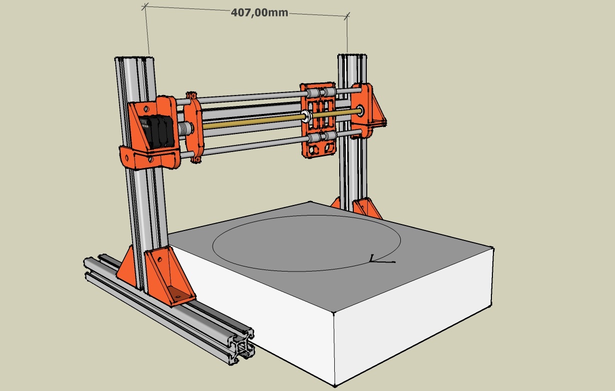
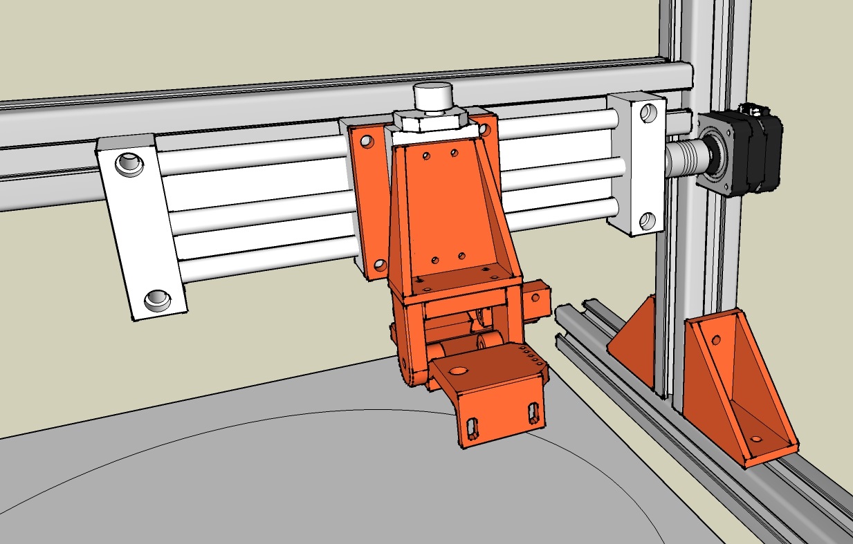
I decided to use them both and modified my design again. And this is how it looks like now:
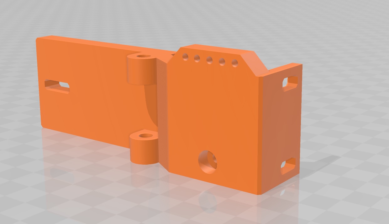
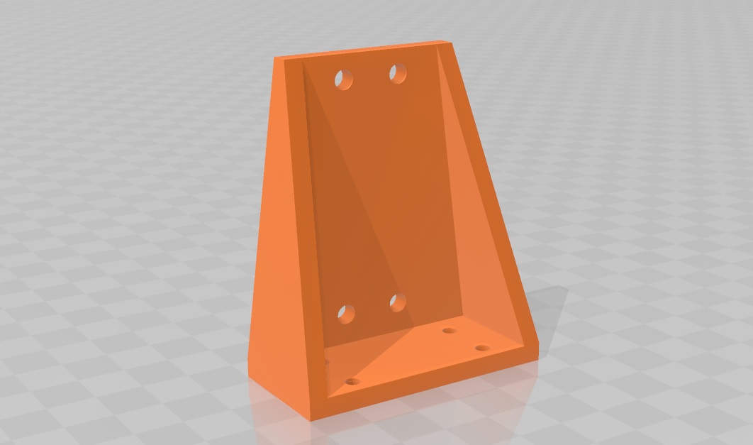
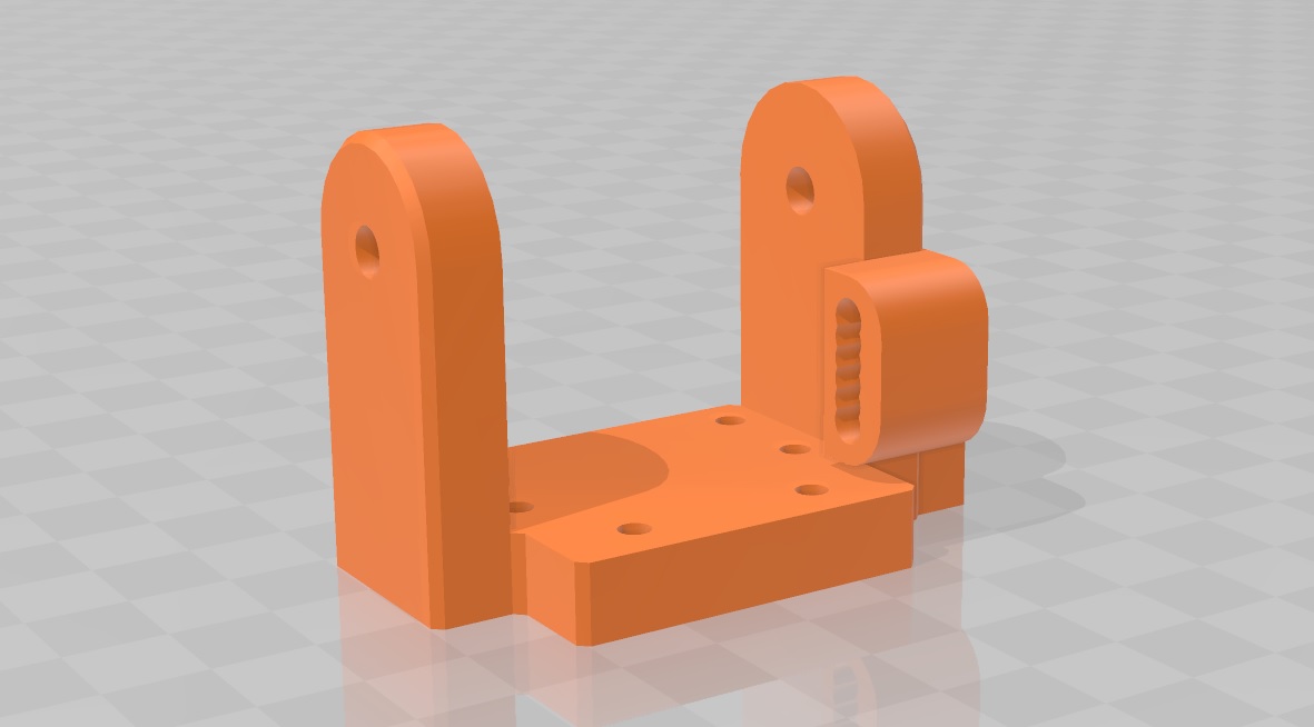
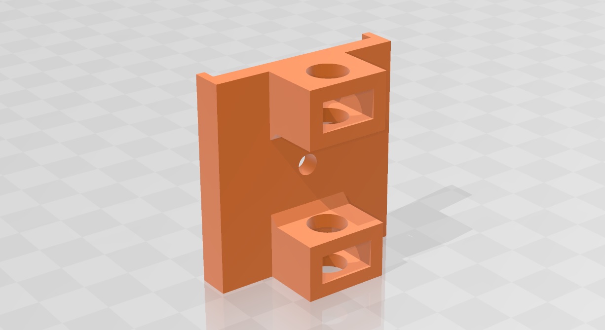
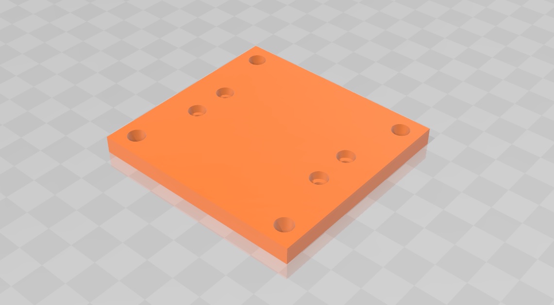
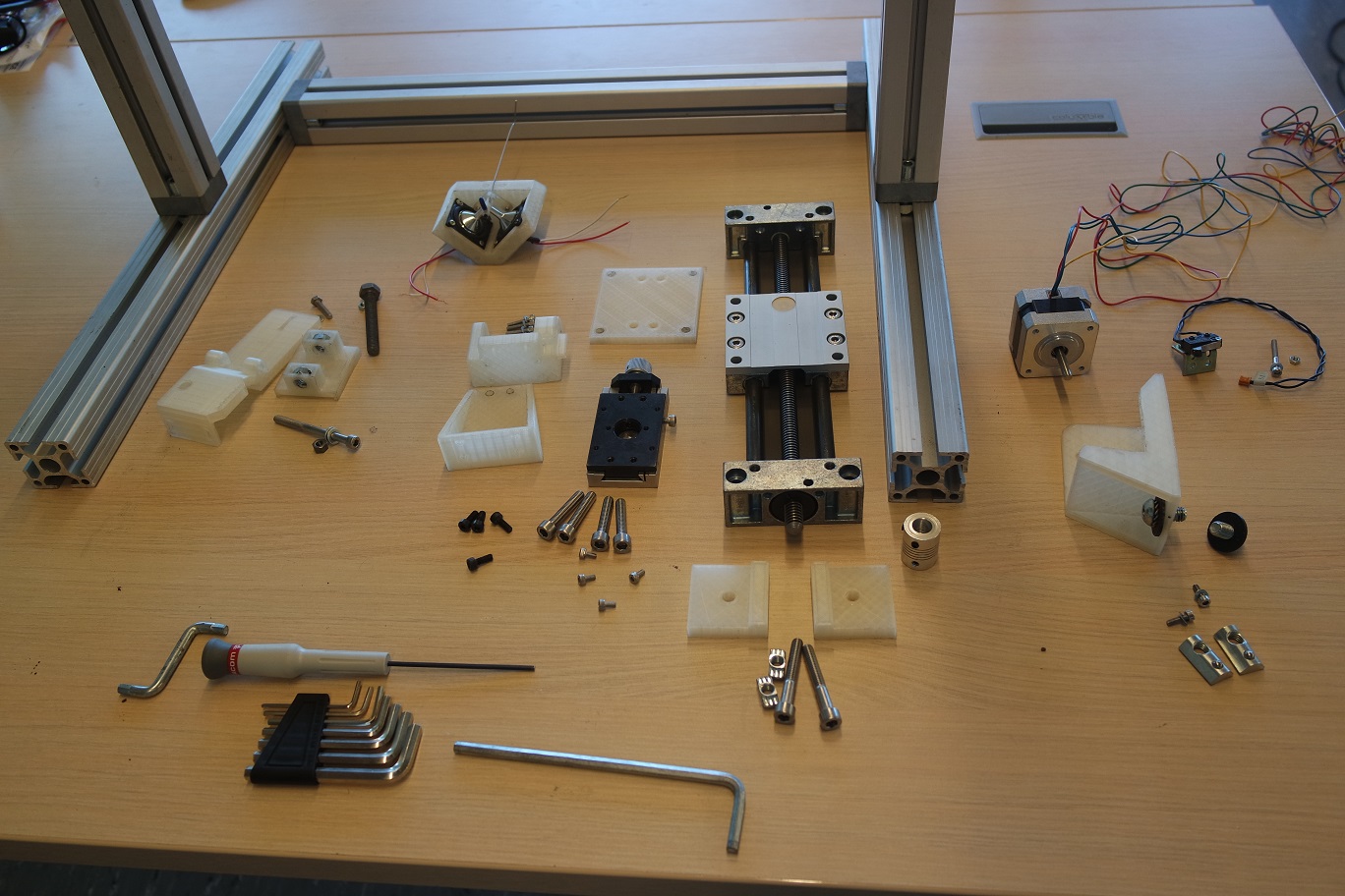
Here are the 3D printed parts that will be needed and that I printed so far:
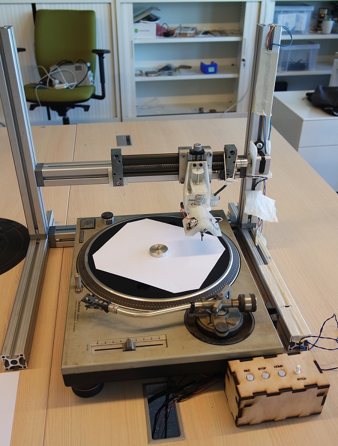
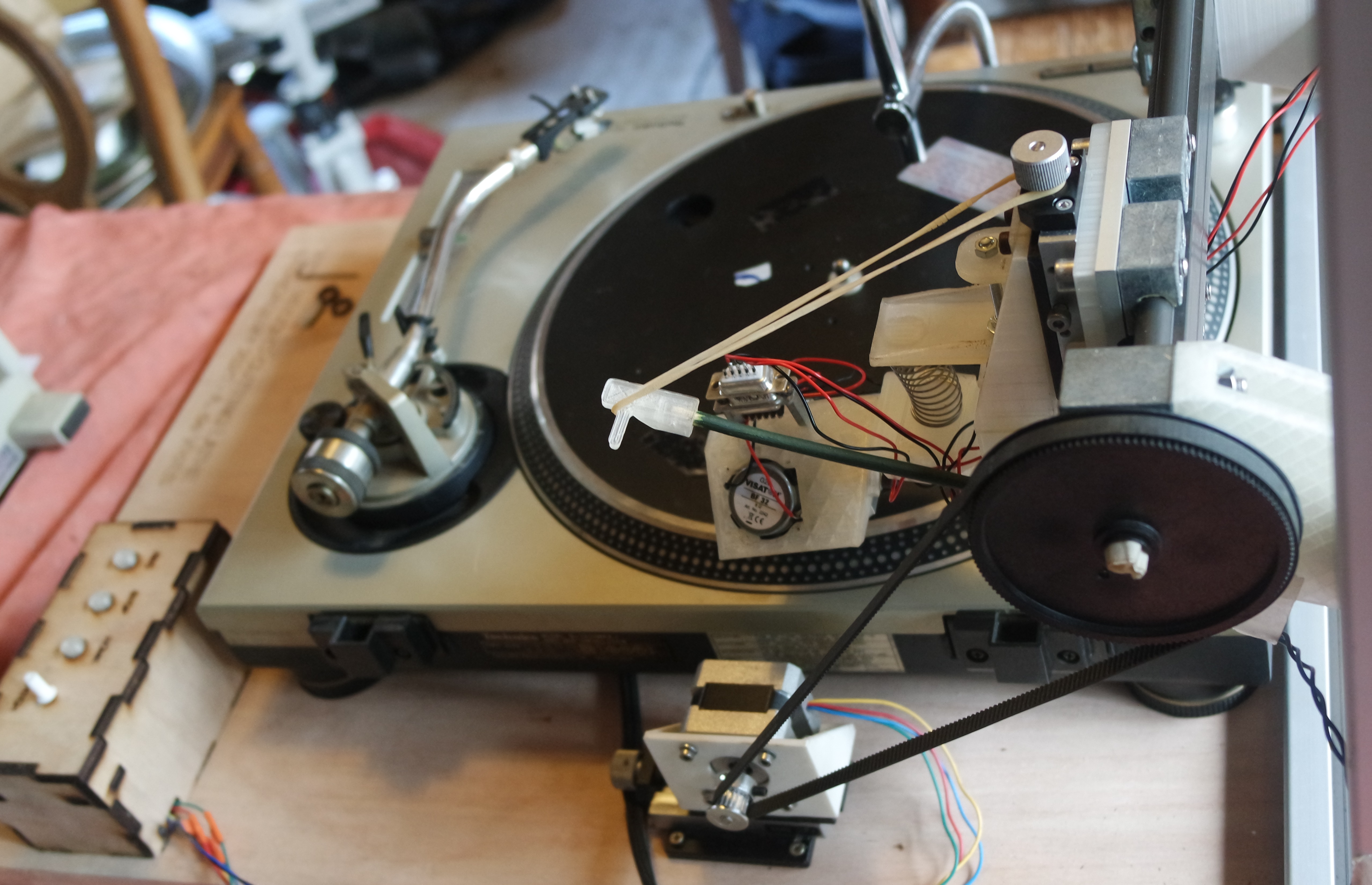
And here is a photo of the real thing.
It's very stiff and uses very few printed parts, nuts, and bolts.
And it's also going to be easier to move it from my home to the lab or the other way round.
Even if it's a bit heavy... but at least it will be steady!
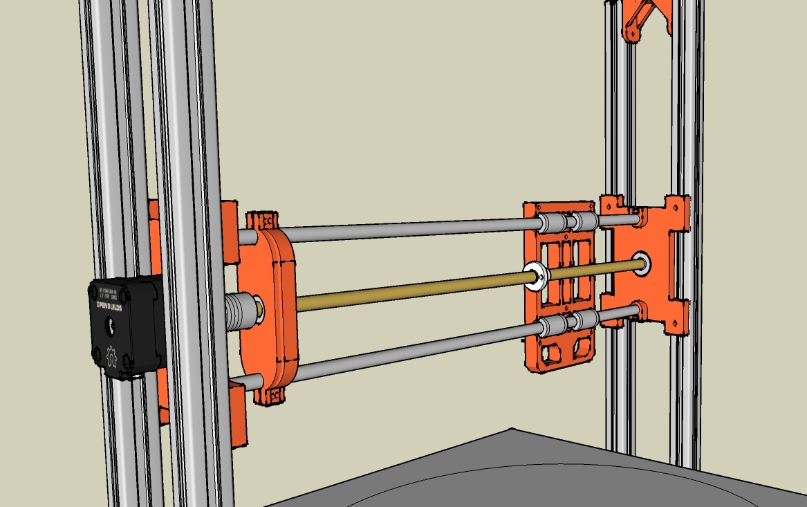
The motor I have is a Nema14 and I'm going to test with that first.
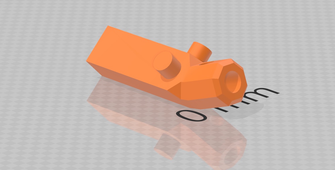
The shaft diameter is 5mm and I need to connect it to the 10mm diameter screw on my X axis.
As I only have 5mm to 8mm connectors I had to drill the 8mm hole back to 10mm:

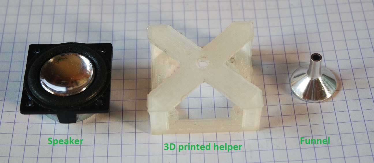
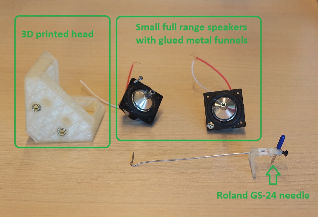
The engraving head isn't completely finished yet and that's going to be the next challenge... I'm going to use small metal funnnels that will be glued to the speakers with 2 parts epoxy.
But they need to be a bit smaller so I had to grind them down to size:
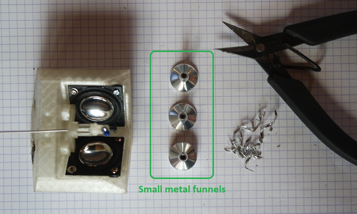
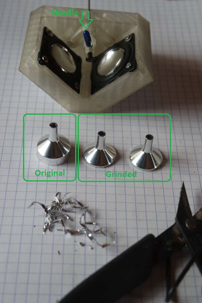
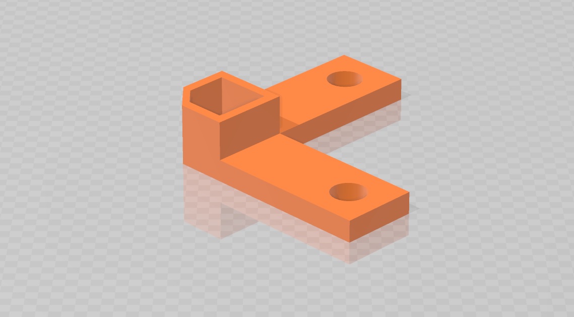
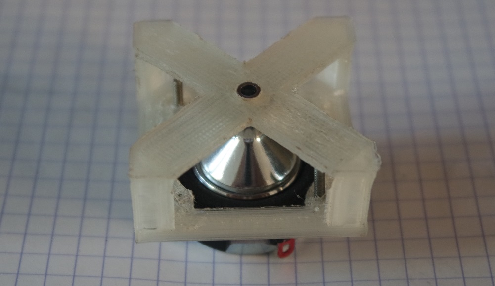
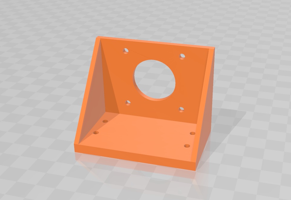
Then I need to fix them to the speakers as straight as possible. To help me in this process, I designed and printed this little "helper" that will hold the funnel vertically aligned while I will apply the 2 parts epoxy resin:
The needle I'll try to use at first is a cutting one from the Roland GS-24 vinyl cutter machine.
Following is a copy/paste of the progress I made during the Project development weeks (week 18 & 19).
Tasks done so far
I'm supposed to do my final presentation on June 11th and that's going to be a challenge regarding what I've done so far and what I still have to do!I realize that I decided myself for this project too late during my Fabacademy...
The idea only emerged during week 14 giving me only 1 month to build a working prototype.
I wish I could have find such a motivating project idea much earlier. And that I could have one more week to present it on June 16th.
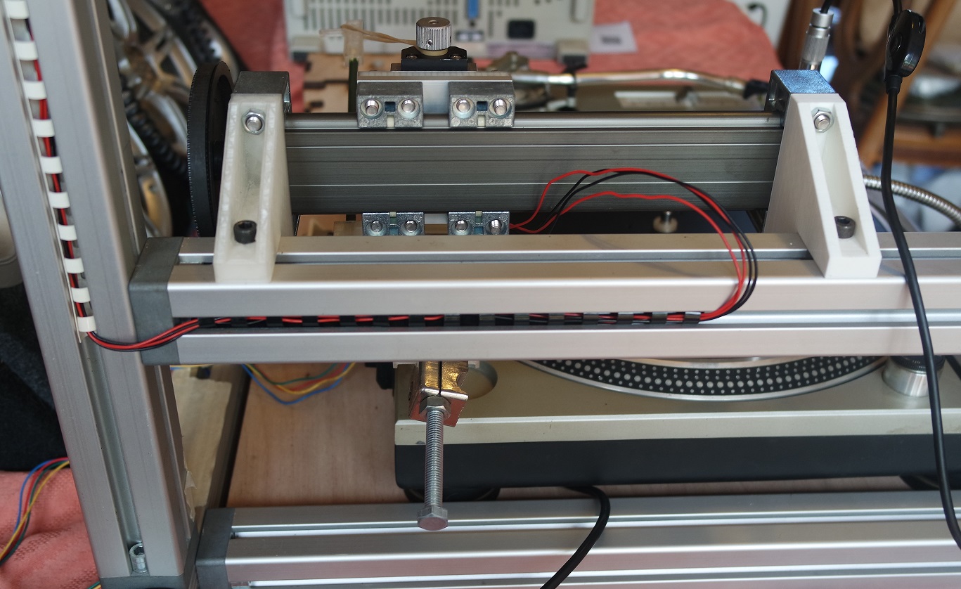
The main structure of the machine is finished.
The frame was built from 40x40mm aluminium extrusions and is very strong and stable which is what I was looking for:
At this point, all the CAD parts needed to build the arm and the engraving head have been 3D printed and assembled:
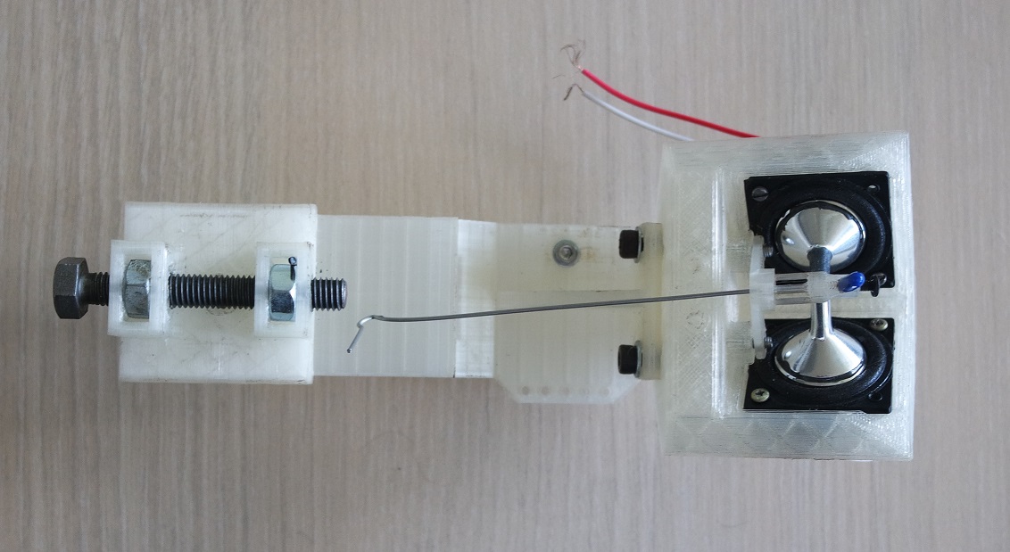
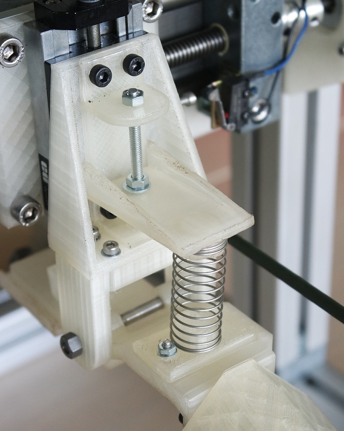
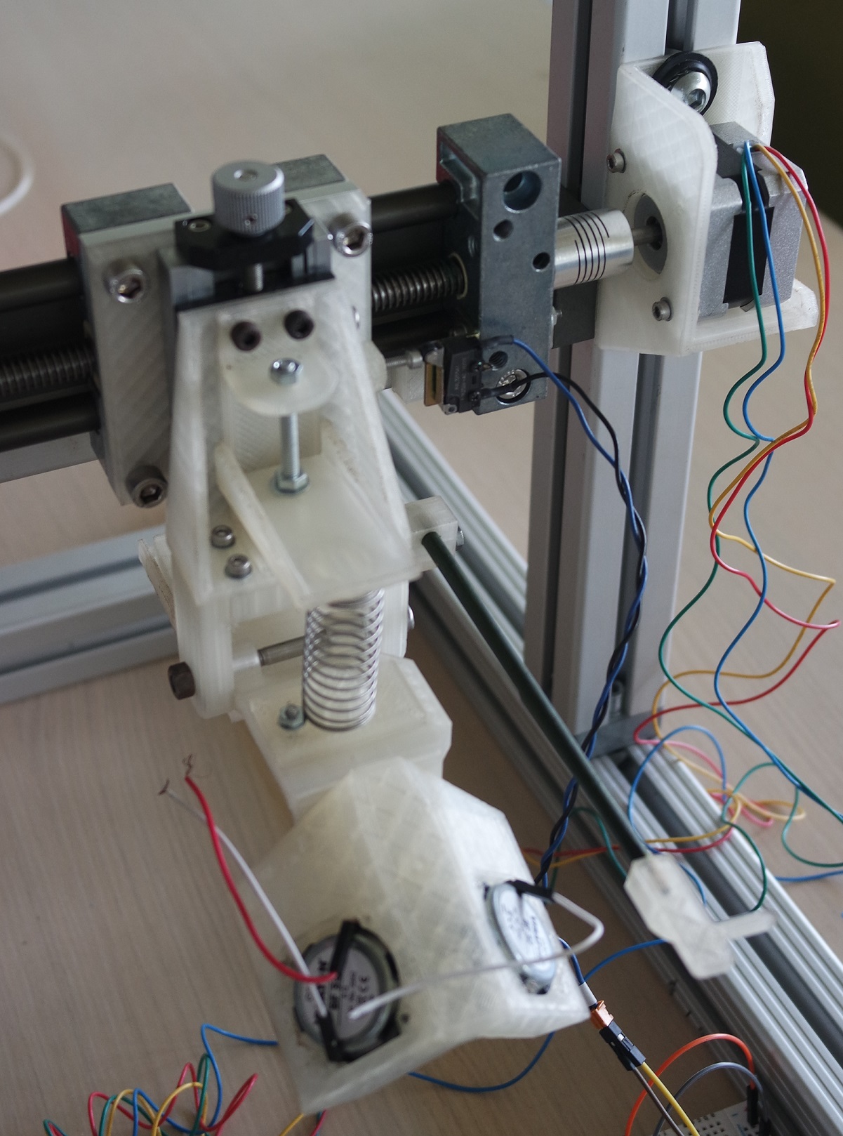
The engraving head has also been assembled with its two tiny BF-32 full range speakers connected to the engraving needle by small epoxy glued metal funnels:

I just finished the first version of the code for my X gantry movement and tested it.
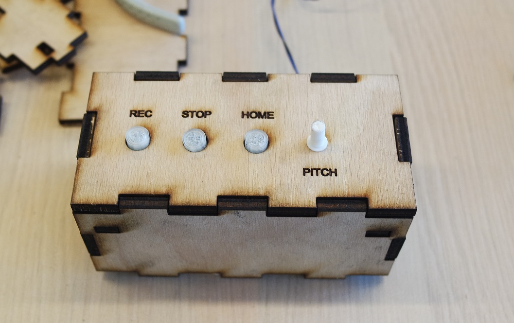
At the moment it's using 3 buttons and a potentiometer for
- starting the recording (REC button)
- abort the recording if needed (STOP button)
- perform homing (HOME button)
- speed fine tuning (SPEED potentiometer)
Remaining tasks
Time is running short and I still have a lot to do!Last week (week 17) I broke my L293D stepper driver by probably making a short circuit and had to use a A4988 stepper driver instead.
And I did all my programming based on it.
So I think I'd better stuck with it now if I want to have a chance to finish on time for the end of the week.
That means I will have to design and make a new electronic board for it because at the moment I'm using breadboards which is far from ideal.
I planned to make a mold and to cast Cerrotru to make a counterweight for the engraving head, but I really don't know if I will have enough time (only 5 remaining days at the time of writing).
I also need to design and make a laser cutted box for the electronic integration.
Do some CNC milling to make a "registering" base for the record player and control box.
Add a servo motor for the engraving head up and down motion.
And of course I also need to provide some sound to the engraving head and perform my first engraving tests.
Questions that need to be resolved
The first one is "will it work?" and can only be answered by testing engraving some sound.The second one is "will noise from the motor will be noticeable on the recording?".
Once again only testing will give me an answer.
If this is the case, I will probably need to remove the motor from the aluminium frame, and use a belt and belt pulleys instead of a direct connection between the motor axis and the X gantry screw.
The third question I have in mind is "will a Roland GS-24 vinyl cutting needle be able to do the job?".
If not, I will probably need to buy and use a dedicated record vinyl embossing needle instead.
And at last but not least "will I be able to finish in time?".
We'll see... I will document my progress for the remaining days at the bottom of this page.
What did I learn?
I learned a lot of things during my Fabacademy!- Electronic design and production
- Soldering
- Networking
- Interface programming
- Molding and casting
One of my 1st advice for future Fabacademy candidates would be to not start it if you don't have a clear idea for your final project.
But if you do, try to find ideas and decide on one as fast as possible to be able to use each week for your final project.
If I had decided right at the beginning, my project would be much more advanced, and I would be much more confident to be able to finish it on time.
I also realized that the Fabacademy is a very intensive program and that it's very hard to go back to studies when you are not so young.
But I'm very proud I did it.
Final countdown
June 7th 2021 (D minus 4)
During the morning I made my first audio test at home to check that the speakers on the engraving head are working fine.But one of the wires that I had solder broke and I will have to solder it back when at the lab.
I also started to search and read about Frequency Response because it's something I will need to measure.
Here are a few interseting links on that subject (and more) that I still need to read and digest:
- pearl-hifi.com
- electroacoustique.univ-lemans.fr
- lesnumeriques.com
- gearspace.com
- freedsp
- electronics-tutorials.ws
- artalabs
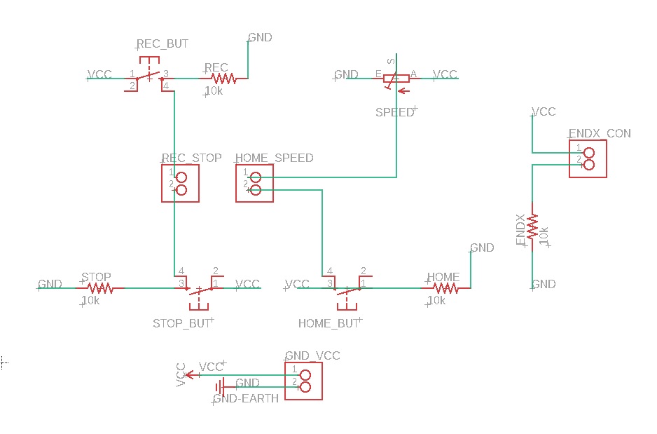
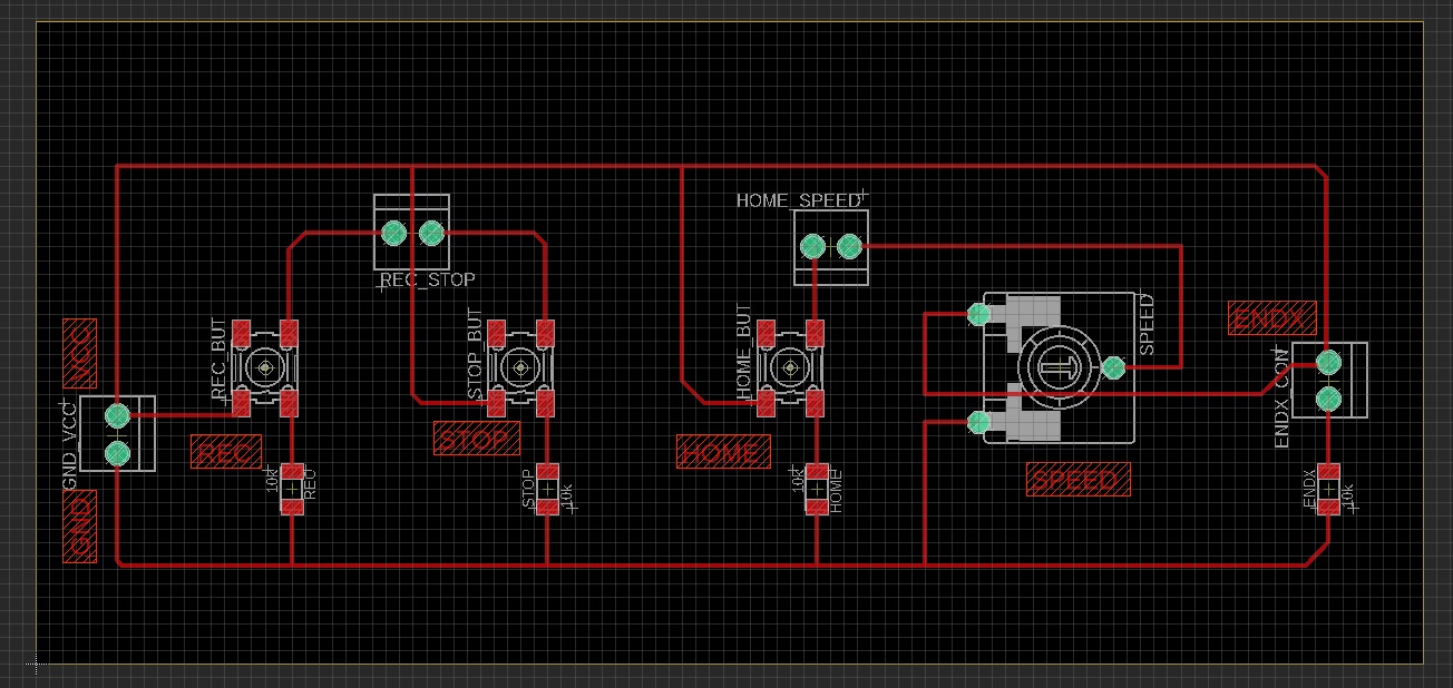
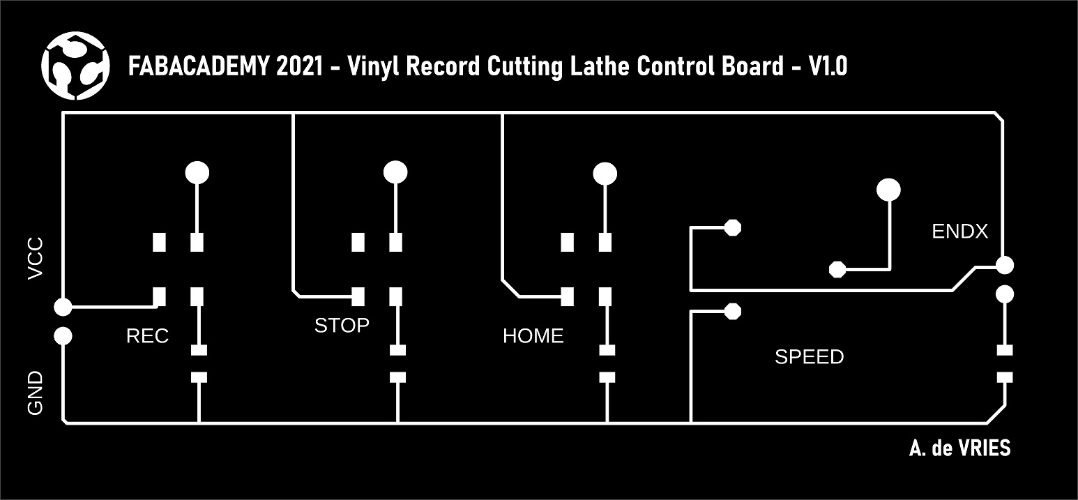
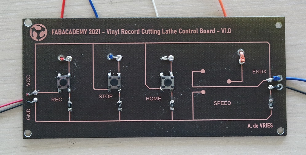
Then once at the lab I designed the board for my buttons and potentiometer:
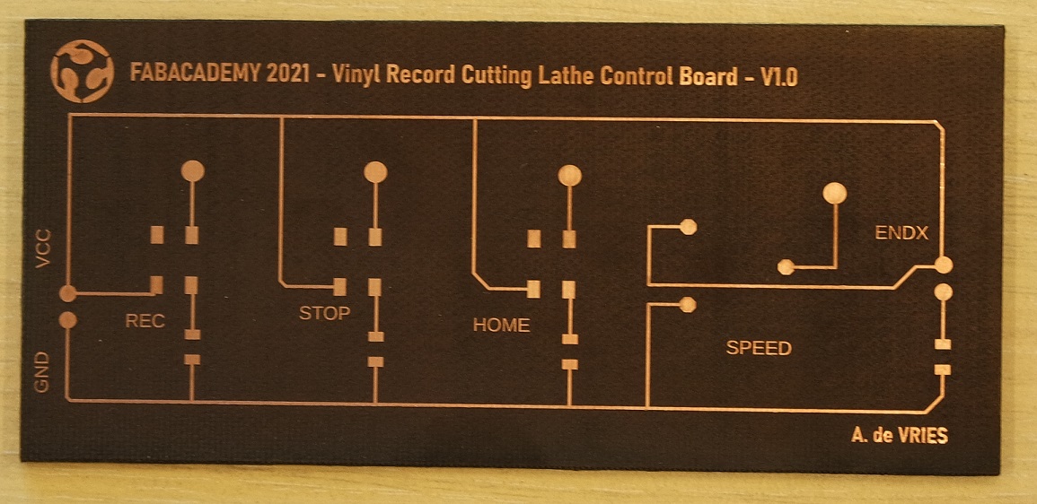
And then I engraved it and will solder it tomorow:
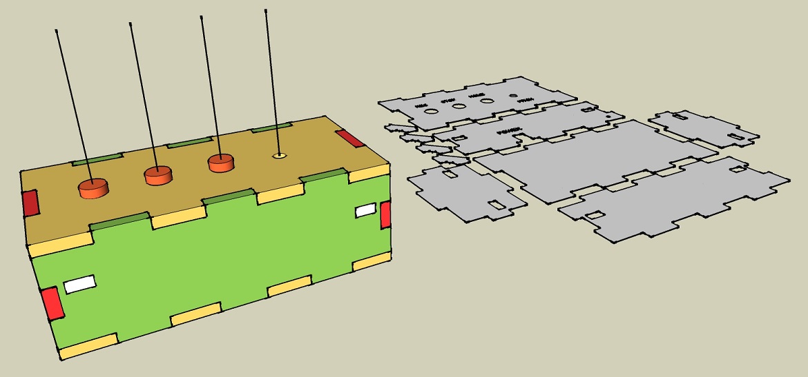
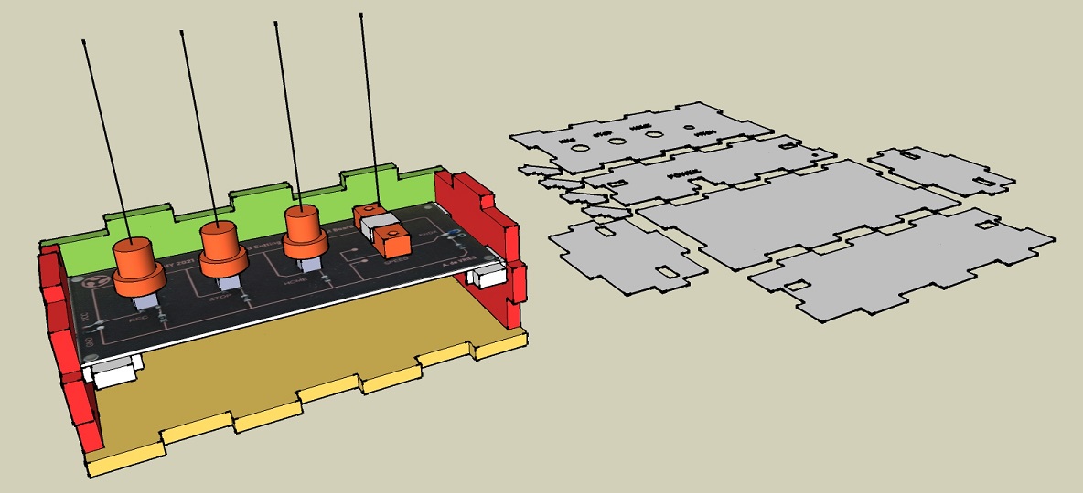
While it was engraving I also started to design a box for the electronic integration (unfinished):
June 8th 2021 (D minus 3)
The first thing I did was to solder my board.Only the potentiometer is still missing because it's higher than the buttons so I want to cut and finish the box to see how I will integrate it:
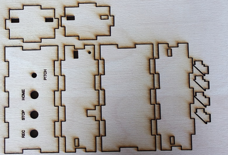
Then I finished the design of my integration box and cutted it with the laser cutter:
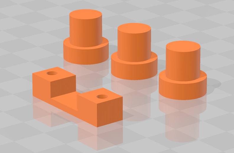
I also designed and 3D printed 3 buttons and a "U" shaped part that will hold my potentiometer underneath the top of the box:
And finally I assembled the integration box with my board and the 3D printed parts to check that everything fits well:
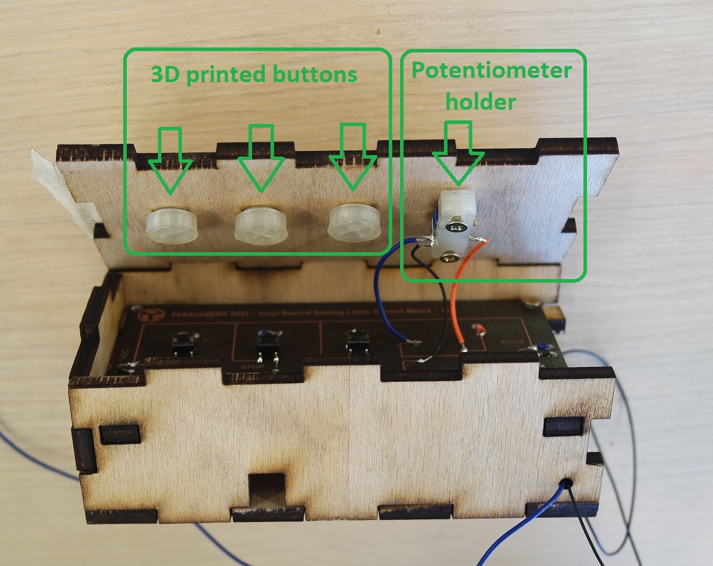
The 3D printed buttons are doing their job and I can here the "click" sound when I push on them.
The box might be a bit too small for everything to fit in it but it should be possible.
If that's not the case I might have to laser cut a second bigger version.
June 9th 2021 (D minus 2)
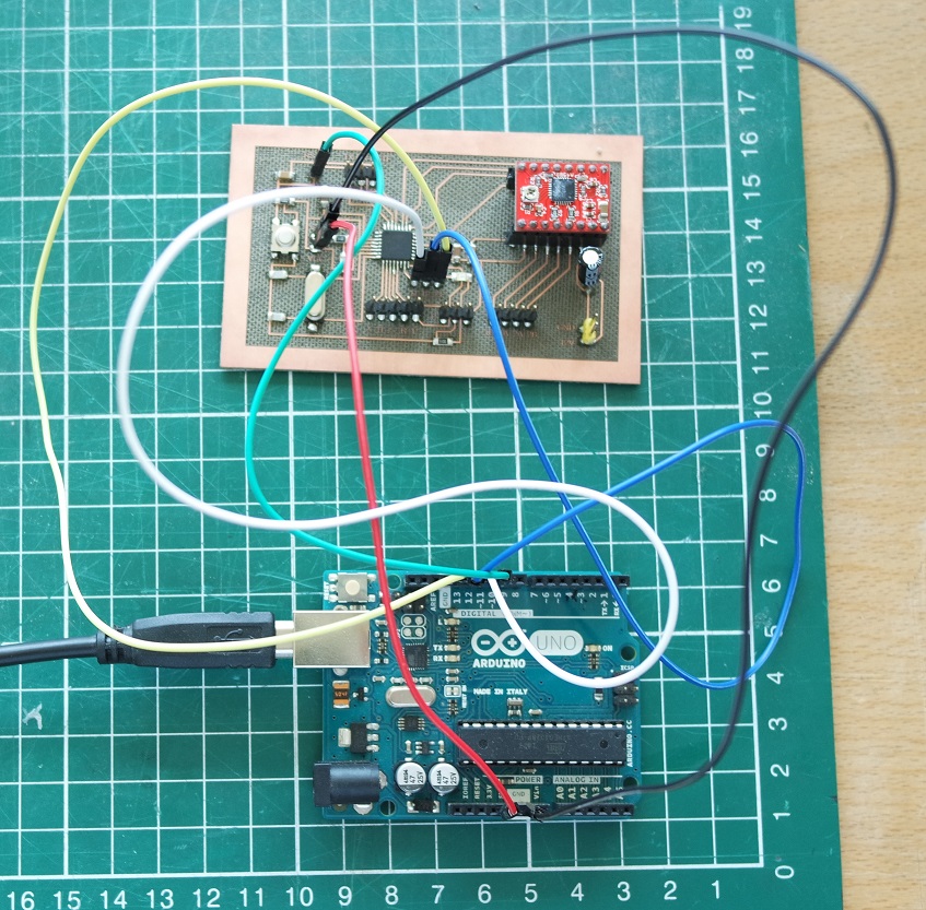
After checking more than twice that everything was connected properly, I tested my board and everything worked as expected.But this test was done on a Arduino Mega board instead of my Satshakit board.
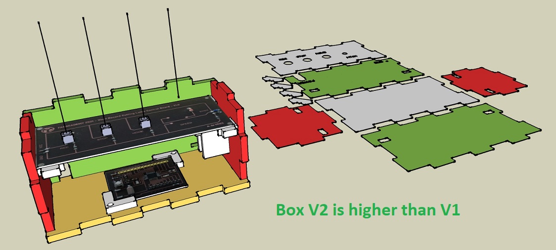
So the next thing I did was to test again with my Satshakit board that I made on week 12 and it also worked.
My Satshakit board is much smaller than the Arduino Mega and everything could probably take place inside my box.
But to make things easier to connect I decided to make a second version of the box which is 2cm higher than V1:
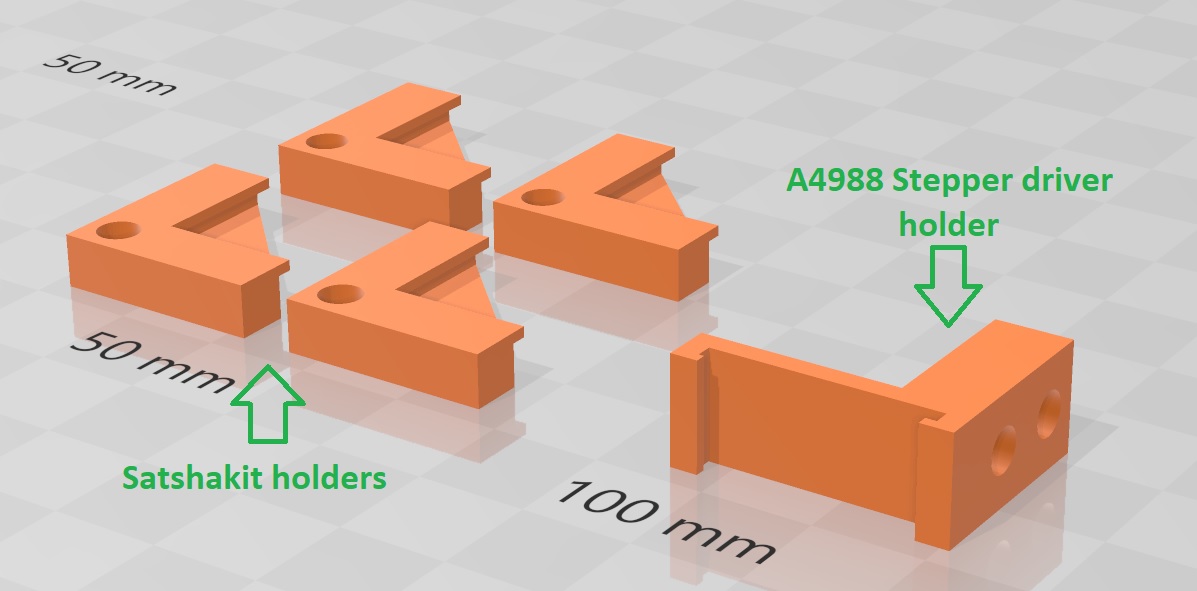
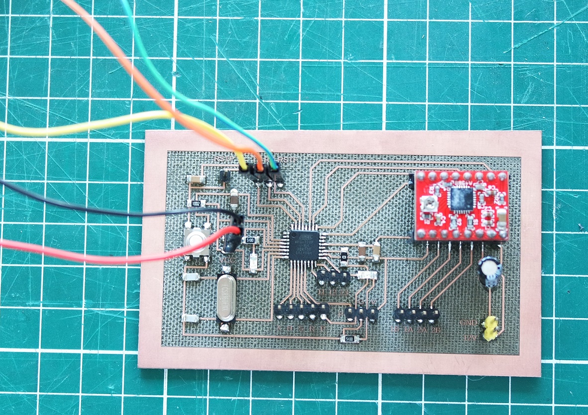
As the Satshakit doesn't have outpout pins for VCC and GND I also had to do a little bit of additional wires soldering.
And I also 3D designed and printed extra parts for holding my Satshakit and the A4988 stepper driver in place:
June 10th 2021 (D minus 1)
Today I assembled back all my electronics into my new box V2 and tested again to make sure it was still working before to close my box: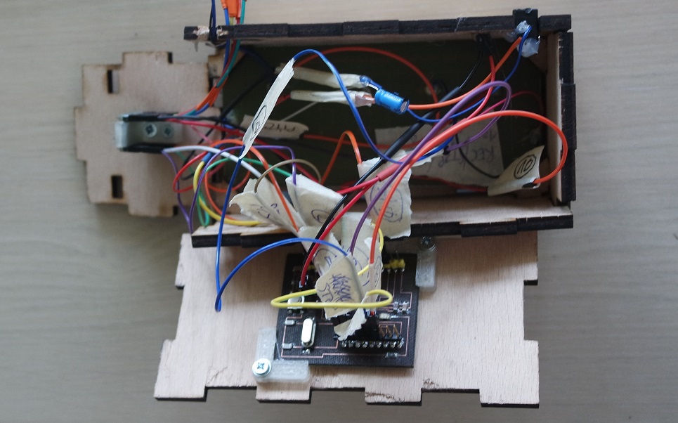
And then I tested again once closed:
As I had bring my Technics 1200 Mk2 turntable with me, I installed it underneath the X gantry of my machine and ajusted all the aluminium extrusion so that the needle is very close to the top of the turntable:
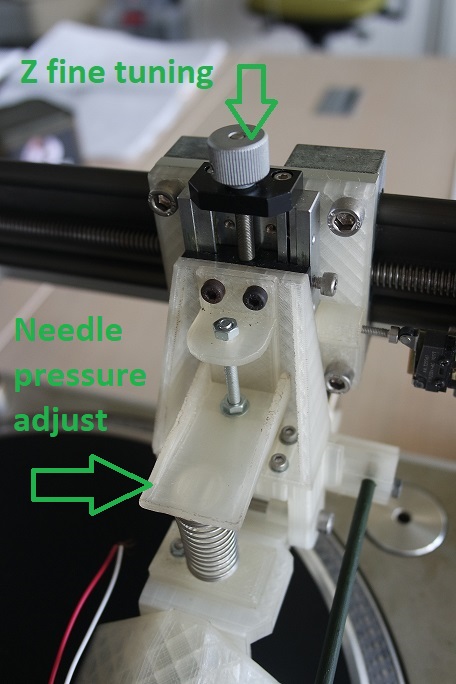
Then I could adjust it even better with the Z fine tuning.
I also adjusted the pression on the needle both by playing with the counterweight at the back of the arm and the pressure on the engraving head spring:
Then I was ready to perform a very 1st test.
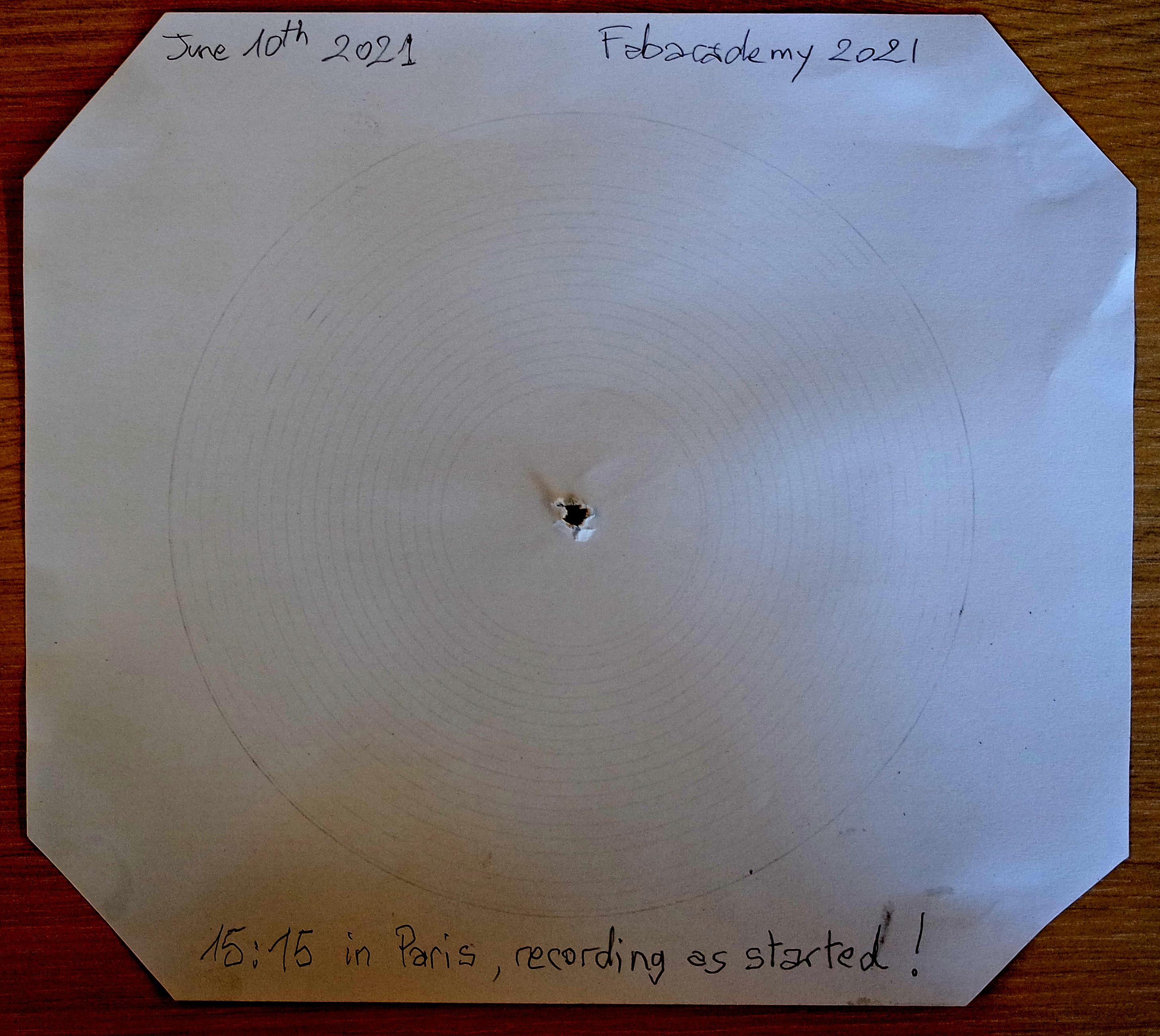
I performed my very first tests on paper by replacing the Roland GS-24 needle by a pencil tip.
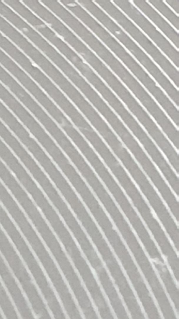
And here is the very 1st result I got at high speed and 33 RPM rotation:
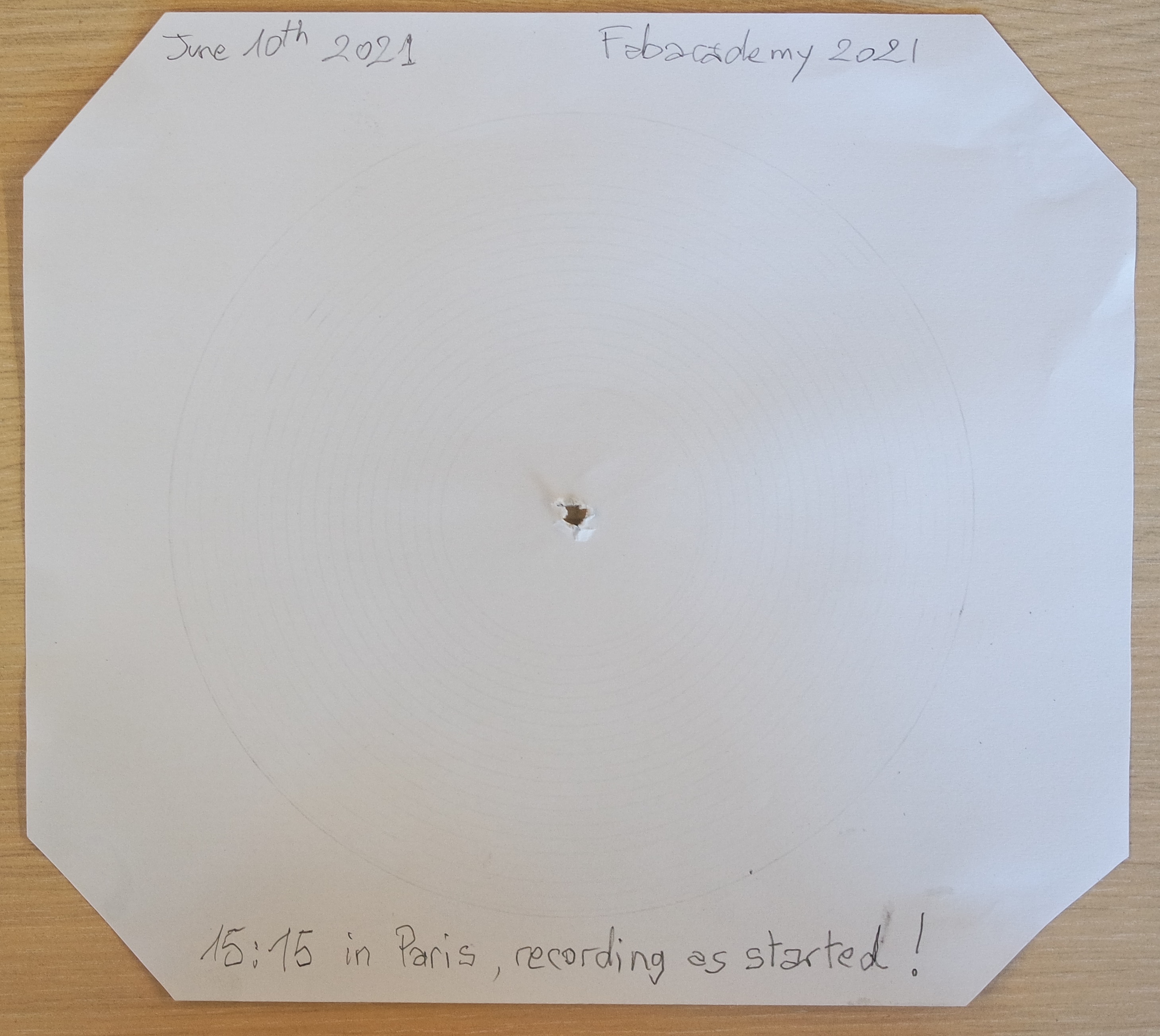
This is exactly the same image on which I enhanced the contrast to better see the groove:
After this 1st test I adjusted the needle pressure again to be able to better see the groove on the next tests.
Then I performed more tests by varying:
- X engraving speed
- rotating speed (33 / 45 RPM)
- counterweight
- needle pressure
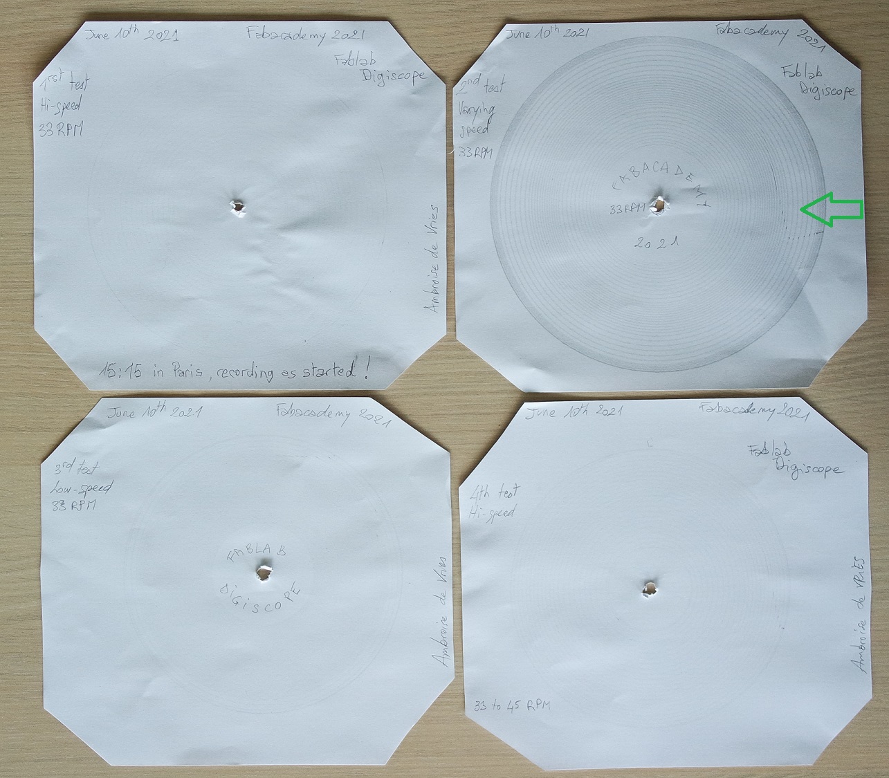
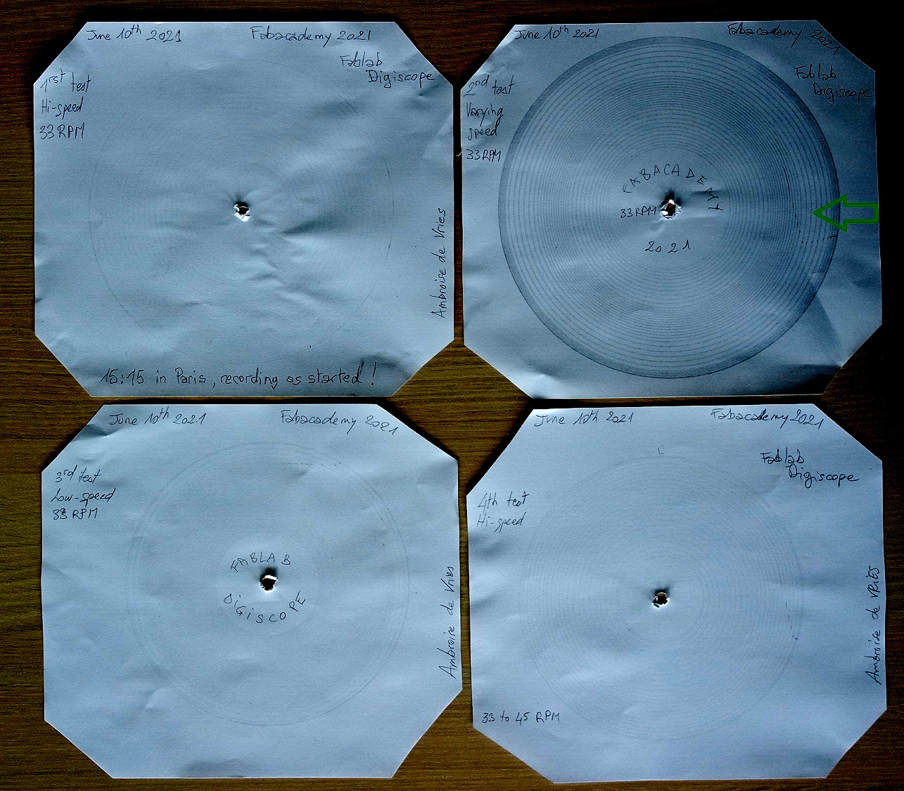
The marks than can be seen on the 2nd test (showed by a green arrow) is the result of this sticker on my turntable:
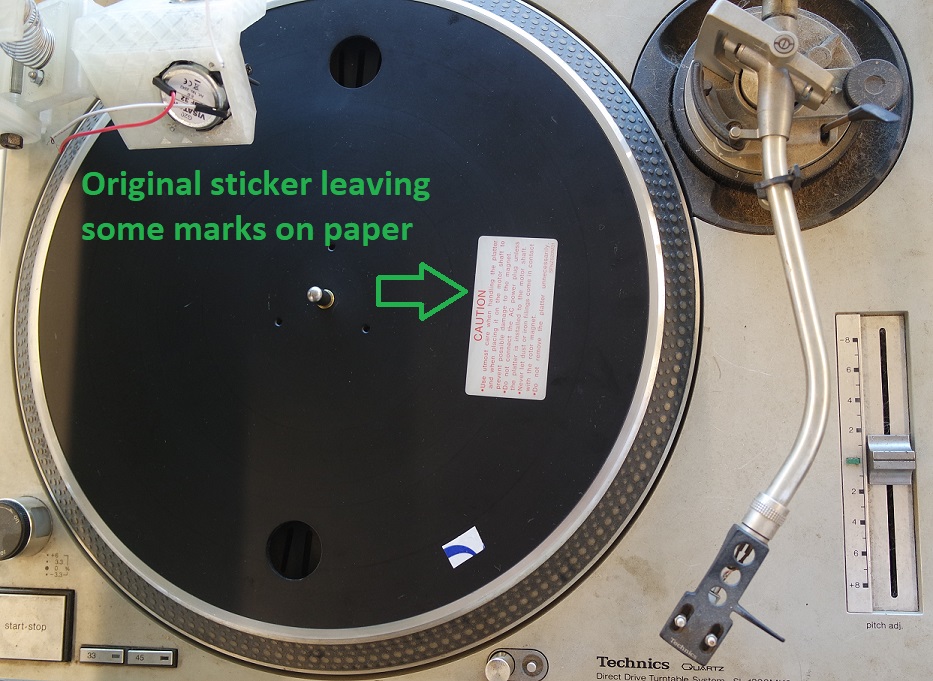
But I won't remove it...
And here is a video showing one of these tests:
Then I spent the rest of my day time to work on my final video presentation.
I'm using Openshot video Editor to produce it.
June 11th 2021 (H minus 7)
This morning I worked again on my final video presentation.It's 1mn and 26s long and I used FFMPEG to compress it down to 9.28Mb.
Here is the link to my final presentation video.
June 14th 2021
Today I performed some audio tests at home because it's difficult for me to bring all my home studio equipment at the lab (pre-amplifier, amplifier, equalizer, and speakers).It's already difficult each time I must bring my turntable because this beast weight 18kg with its flycase!
The sound coming out of the tiny BF-32 speakers seems to be loud enough but I can't see the needle moving just by eyes.
It would probably need to be seen under a microscope.
I will try real engraving tests with audio during the next week-end when I will bring the lathe back at home.
I also started to read and learn about the audio mastering process for vinyl cutting.
Here is a list of the most interesting websites I could find on that subject:
- Music File Preparation
- Vinyl record audio preparation
- How to prepare audio master
- Pro-tools
- Vinyl mastering
- Preparing audio for vinyl
- Mastering for vinyl tips
- Vinyl mastering
- How to master for vinyl
- How to mastering and vinyl cutting
- The Mastering Engineer’s Handbook (a must read)
June 15th 2021
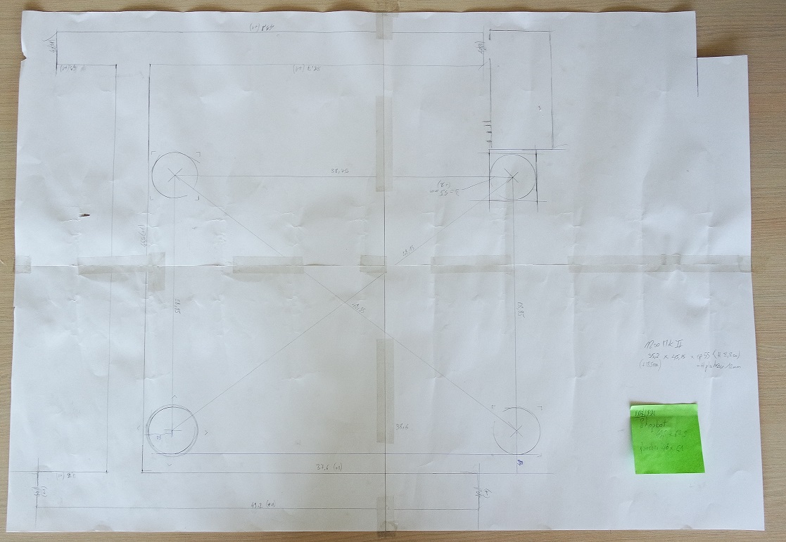
I had plan to mill a thick piece of wood on which my turntable could take place in pockets so it can always be at the same place regarding the frame.It will also have another pocket for my electronic box to avoid it moving.
As I couldn't find accurate dimensions for the Technics 1200 MK2 turntable, I first made a template on a big sheet of paper to deduce all the dimensions I needed:
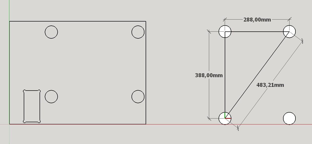
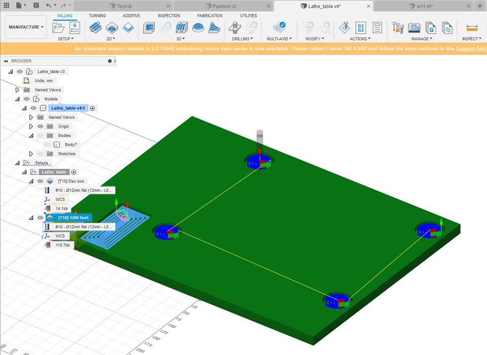
Then I could reproduce it in CAD for my milling process with the Shopbot:
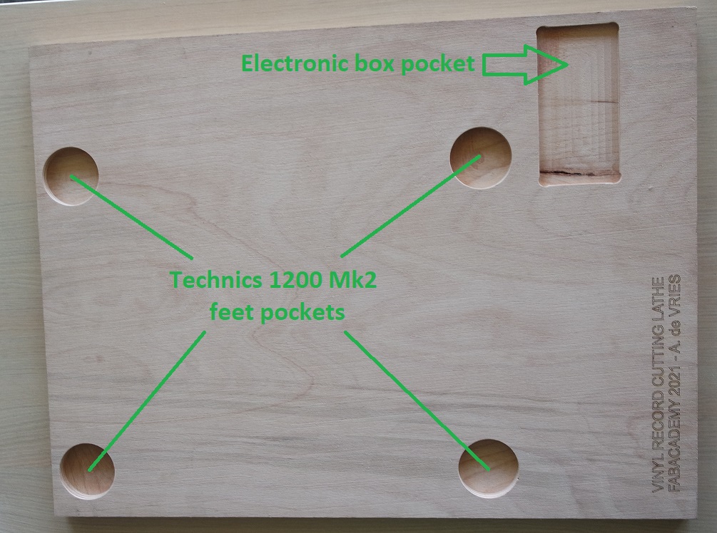
And here is the milling result (with laser engraved text added):
And here placed between the legs of the lathe with my turntable in place:
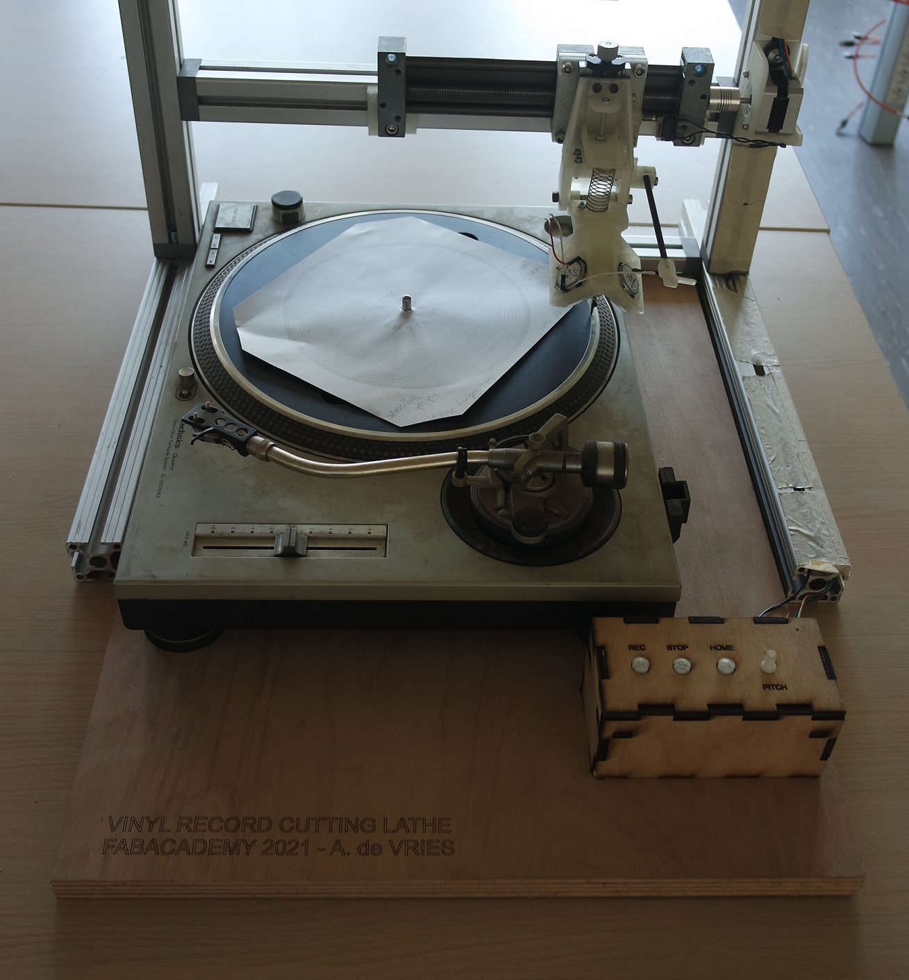
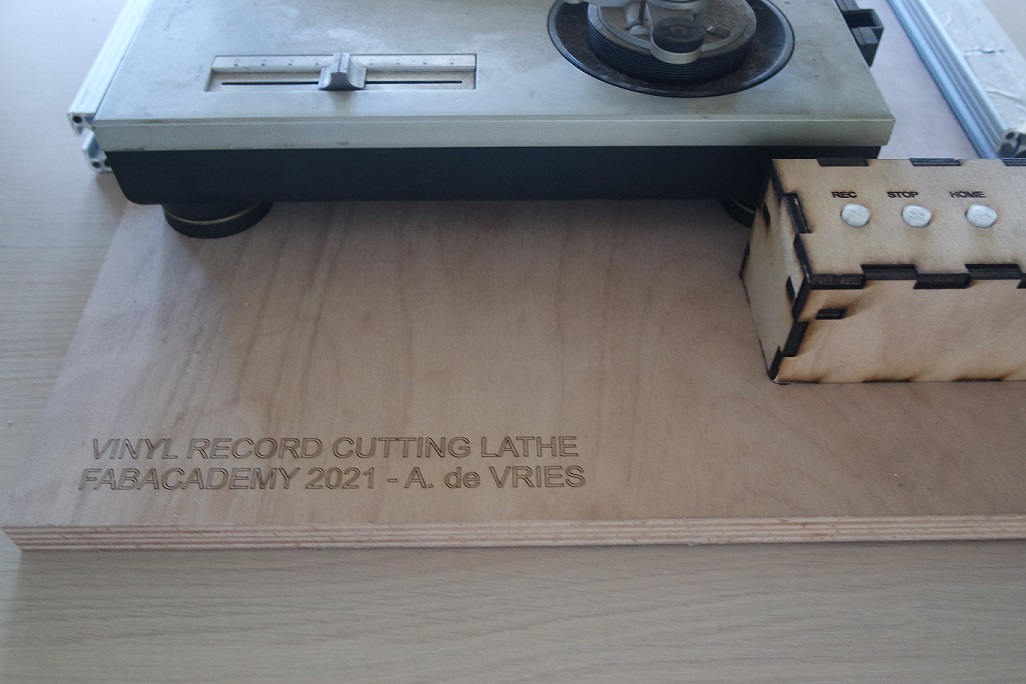
This way I can easily replace the turntable exactly where it needs to be very quickly and the control box doesn't move around.
June 19th 2021
This saturday I prepared everything to be able to engrave some sound before the end of the week-end.So I have read more and more advices on how to prepare audio files to be cut on vinyl (sound mastering), and made myself an audio setup.
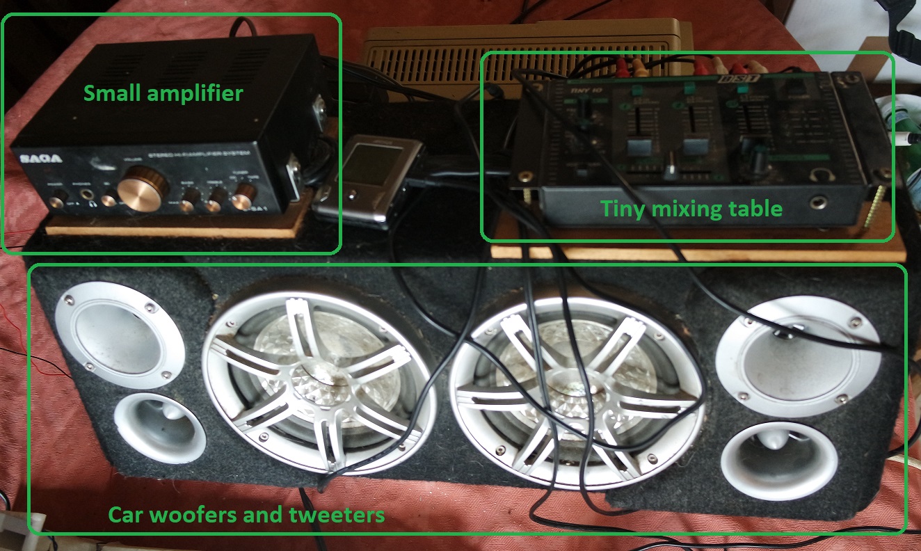
I could have use a big pre-amp, a big amplifier and an equalizer but I wanted to try to have something more "portable" in case I want to be able to go recording outside for some live recording sessions.
So instead I used a small amplifier that I had (probably the worse one I have but its size is interesting), a tiny mixing table, and some speakers that you usually find in cars (mine has been salvaged years ago from the trash).
I quickly put everything all together with screws so I can just carry it by the handle (still a bit heavy) and here is a photo of this setup:
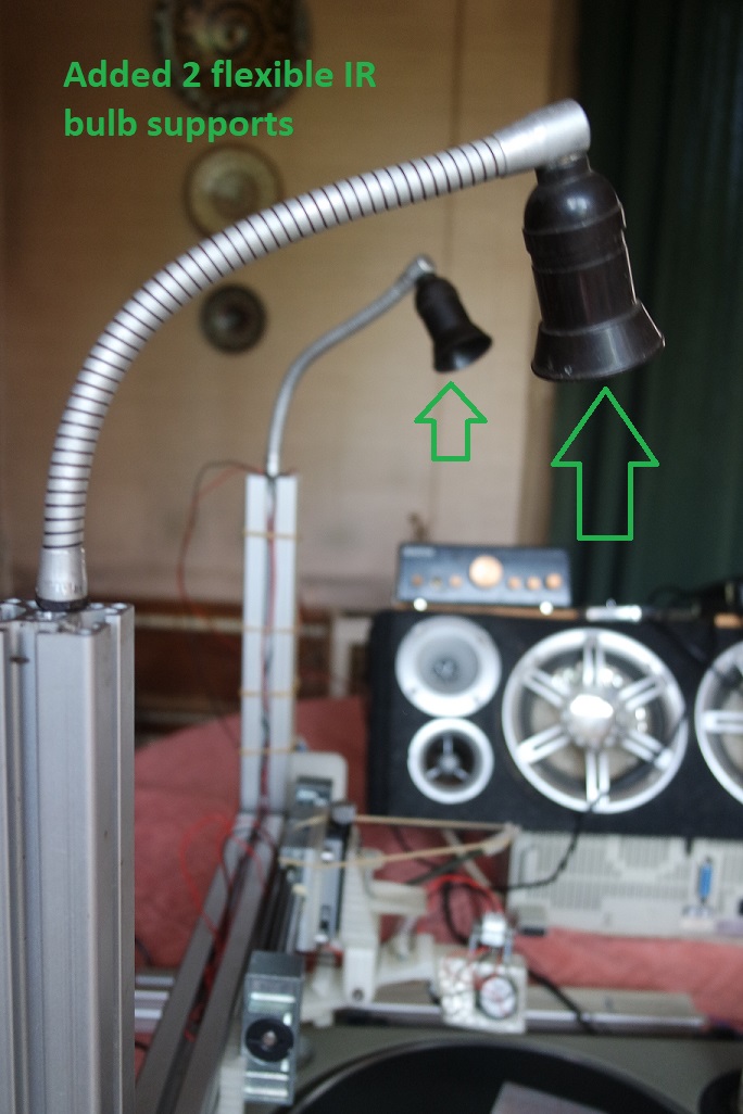
I also added 2 flexible gooseneck that will serve to warm up the media with 2 Infra-Red light bulbs when I will try real cutting instead of embossing:
June 20th 2021
Since June 16th I cannot work on my project anymore except during my week-ends.So this week-end I felt ready for engraving my very first cut on a CD-R.
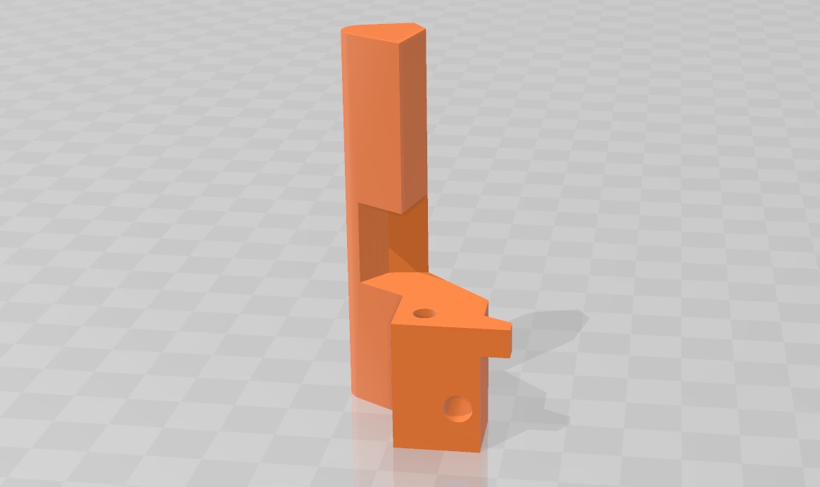
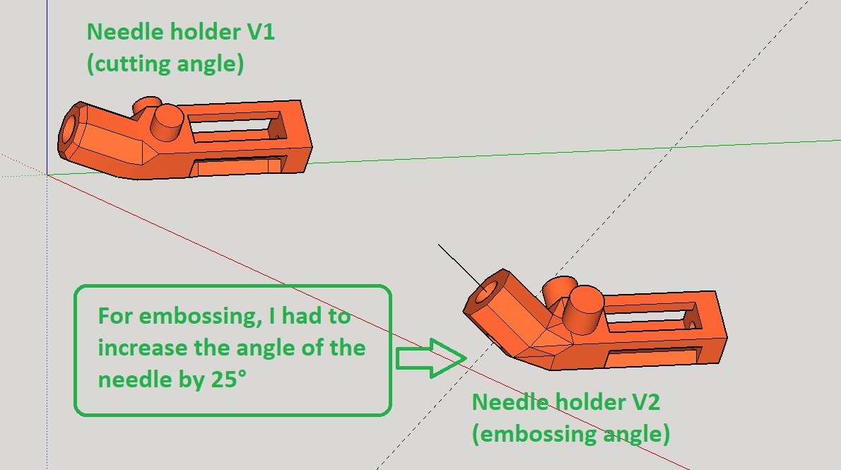
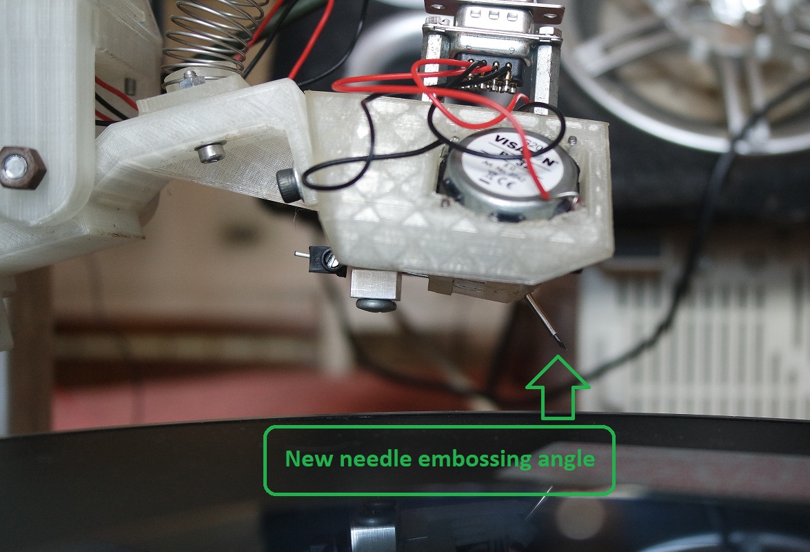
But before proceeding, I figured out that my needle will need more angle relative to the media surface to be able to emboss, so I redesigned the needle holder with a 25° accentued angle compared to the previous one and printed it:
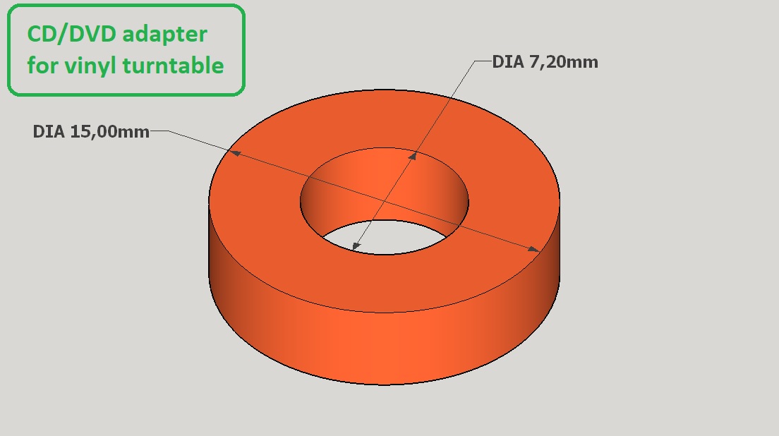
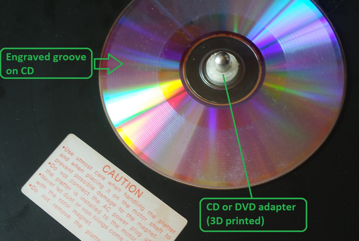
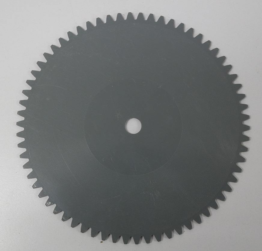
I also needed a diameter adapter to be able to spin a CD-R on my turntable so I designed this very simple one and printed it:
The very first test cut I did was engraving a "white noise" at 45RPM (no sound provided to the engraving head).
I didn't record a video of that very 1st engraving test but it worked suprinsigly well.
But I made a video of the playback of that "white noise" engraving where we can clearly hear the rumble sound made by the motor.
While I know this is something I will have to improve, it's very encouraging because I know that the turntable is able to follow the groove and that the needle does engrave any small sound variation.
Here is the "white noise" playback:
Video TODO
For my first test with sound I decided to choose a calm tune without too much drum or bass.
So I have choosen a tune by the Romanian artist Dona Dumitru Siminica. The tune is called "Afara e intuneric".
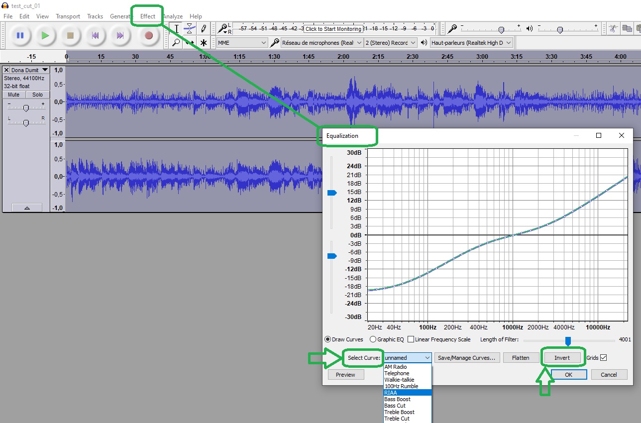
But before to proceed I had to make some mastering work and I used Audacity wich is a free to use and open-source DAW.
What I mainly did is to
- use a highpass filter at 150 Hz
- use a lowpass filter at 15 kHz
- use an inverted RIAA curve
Here is a video of the engraving step at 45 RPM / Mono:
And a video closeup of the same testcut seen from another angle:
And here is a video of the playback step showing that the result is very encouraging if I can minimize or eliminate the motor rumble in the future:
Then I made a second test with sound but this time I wanted a tune that has more drum and bass in it.
I have choosen a tune called "Surfin'" by Ernest Ranglin.
It worked very well but I think I recorded it with too low volume.
Here are the videos showing the engraving and playback steps (45 RPM / Mono):
In conclusion I am very happy to see that it works, and I will now spend time at trying to improve my machine (motor noise, servo motor arm lifting, making a precision turntable with high torque), settings (arm weight, engraving speed, RPM speed, code, etc), and sound mastering knowledge.
I think the quality of the audio could be improved a lot by just engraving less deep by fine tuning the needle pressure and counterweight.
Doing so it will probably minimize the motor noise.
But I will have to do it on my sparetime so I will only be able to work on it again on my next week-end...
June 27th 2021
This week-end I made more tests by fine tuning the pressure and weight of the engraving head and got much better results with less noise.I performed these tests at 33RPM to see how much recording time I could achieve on a blank CD.
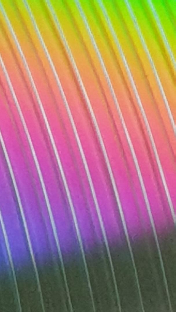
Here is a close-up photo of one of these recordings where we can see I could go even slower and probably could double the recording time:
I also performed a test on some plastic sheet that I had at home without knowing what kind of plastic it was, but the sound quality was of lesser quality.
This is probably due to this plastic being harder than a CD surface:
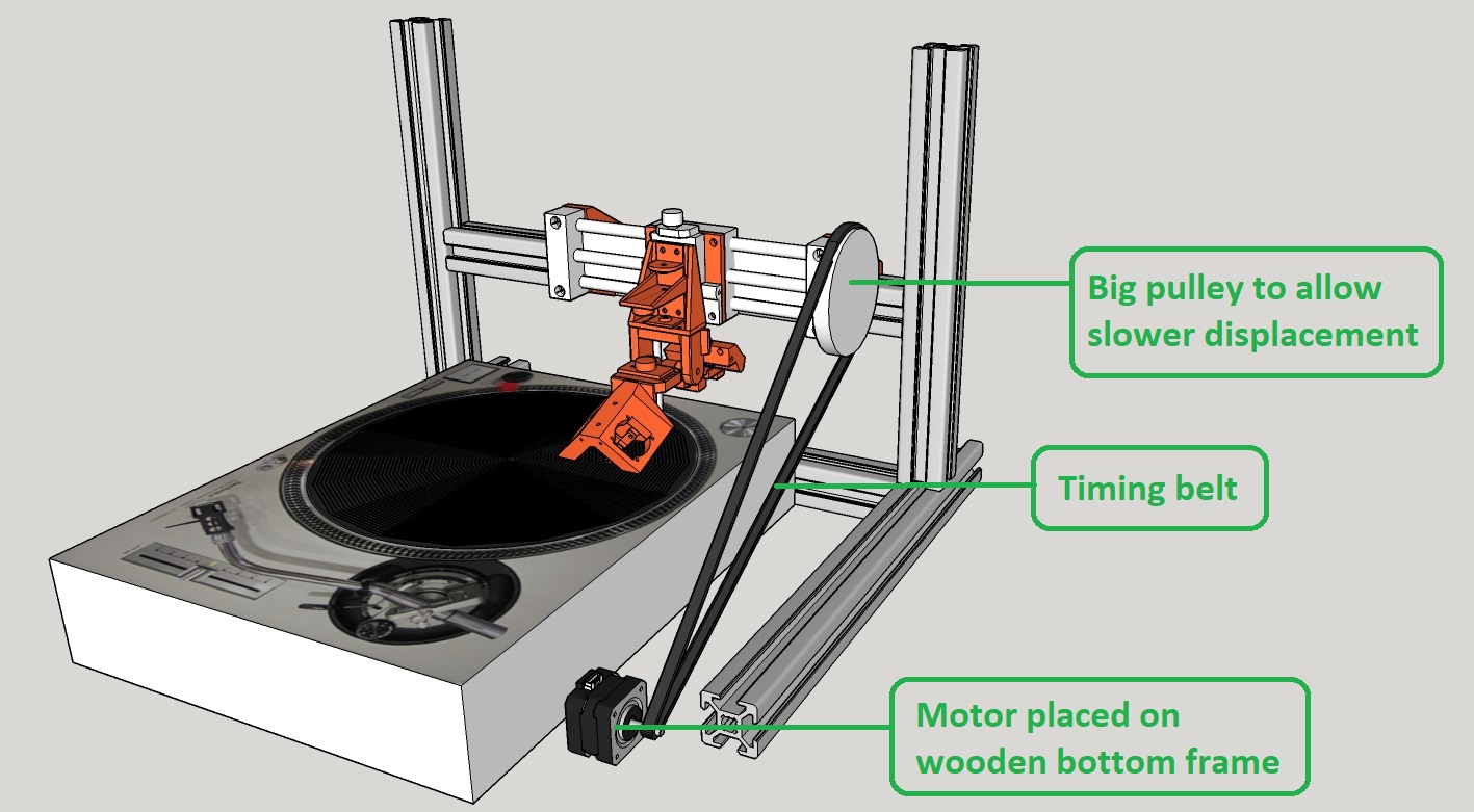
But to be able to go even slower, and also to reduce even more the motor vibrations and rumble, I realize that I will have to put my motor away from the aluminium frame and to use a big pulley to achieve slower displacement without reaching the NEMA lower speed limit.
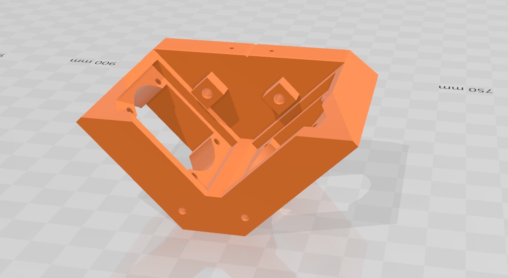
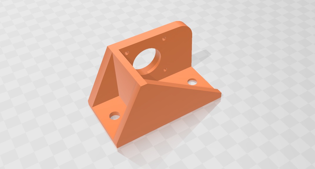
So I started to think about its new location and adapted my CAD design.
I have to 3D print this new part twice plus a new motor holder:
This new design will also give me more room to fit a servo motor to automatically lift the arm at the end of a recording:
I will upload some sound results from these tests as soon as possible.
To be continued...
August 2nd 2021
During the last weeks I designed a new PCB for my project to fullfill the requirements.Until then I was using an original Satshakit that I had made on week 12 and that worked fine.
So for my design I decided to make a derivative of the Satshakit.
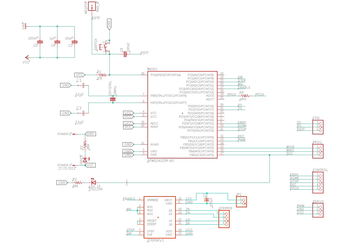
Here is the first Eagle version of my schematic and board:
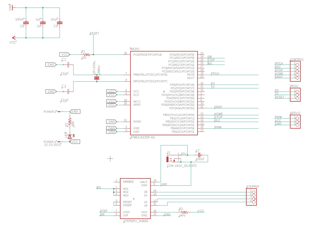
I soon realized that I made several errors with my design which are:
- no connections on MISO and MOSI
- servo motor PWM was connected to a non PWM pin (the SCK pin which is needed to burn the bootloader)
The biggest consequence was that I couldn't burn the bootloader to turn my board into a Arduino Uno like I had done with the original Satshakit.
I was angry with myself and frustrated to make this PCB for nothing so I started to think if I could overcome the problem.
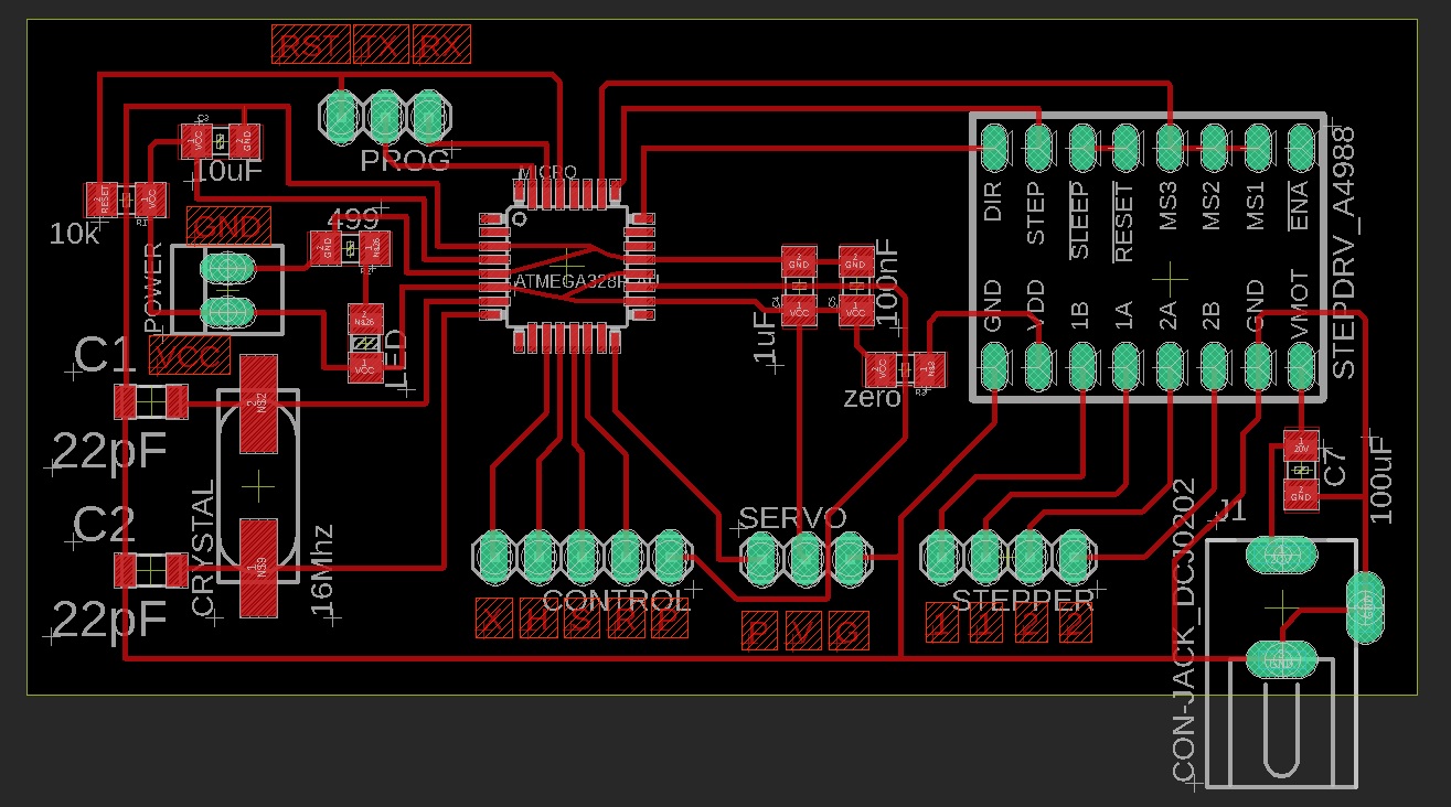
By soldering two wires on MISO and MOSI I could probably burn the bootloader and I wanted to try that to be able to figure out if there wasn't any other unseen problems before making a new PCB.
The soldering tip I have at home is quiet thick so it was a bit tricky but I managed to do it.
Here is a photo of these 2 extra wires on MISO and MOSI:
It did work and I was finally able to burn the bootloader.
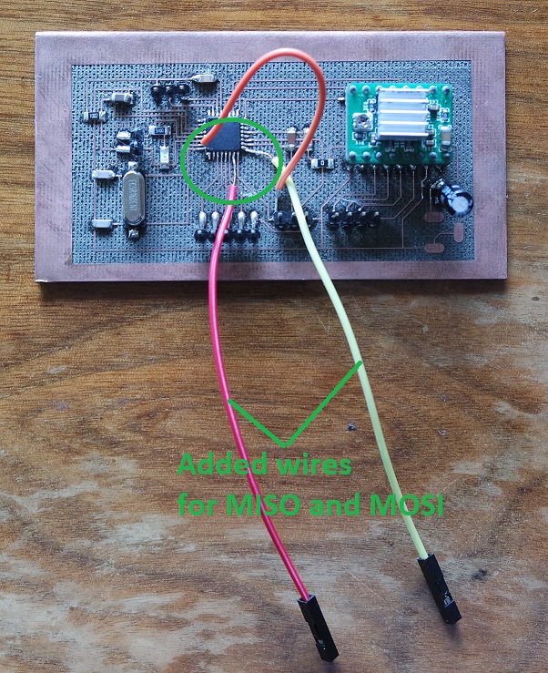
But when it came to upload my arduino sketch another problem occured. It wasn't working because my RST pin was connected directly to the microcontroller RESET pin.
While this is fine for burning the bootloader, when uploading a sketch it has to go thru a 100nF capacitor.
That's why there is 2 RESET pins on the Satshakit (RSTF and RSTP). This is something I understand much better now. The solution was to cut the RESET trace and to add a 100nF capacitor in place.
Once again it did the trick and I was finaly able to load my arduino sketch.
Here is a photo of the added capacitor:
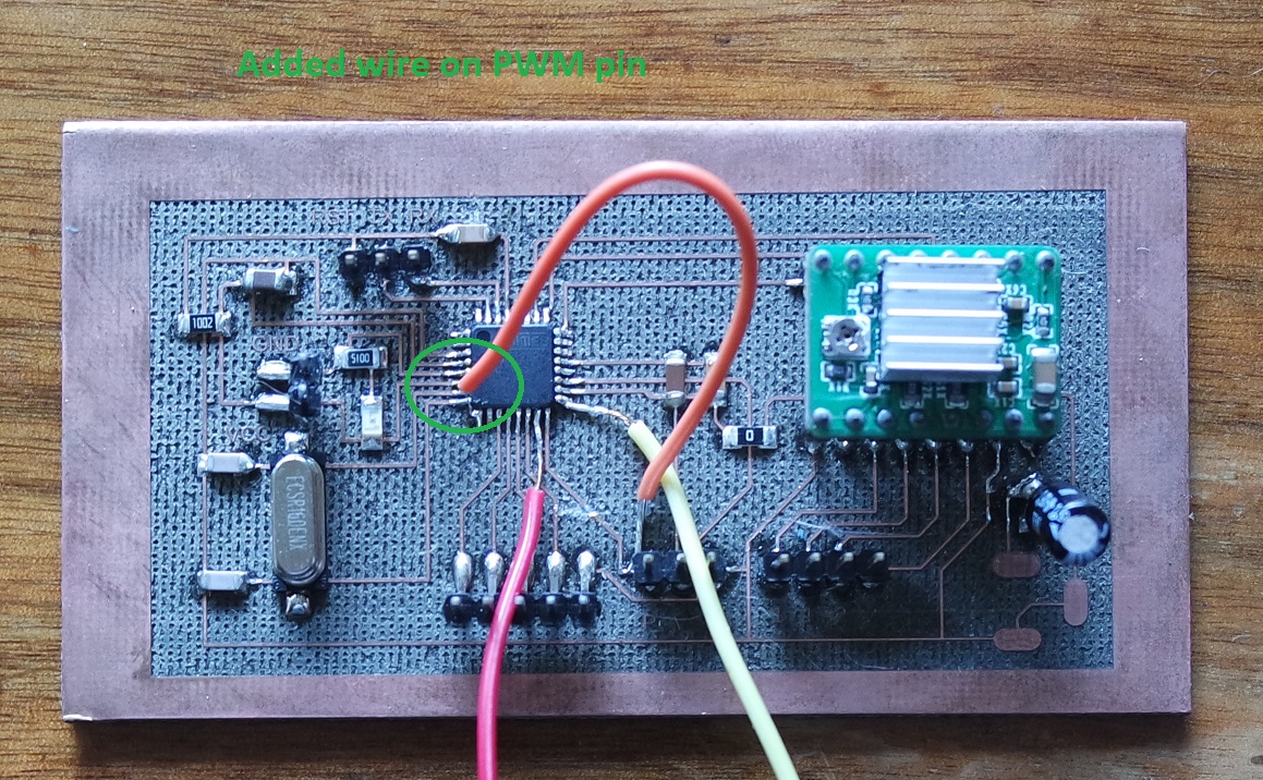
Then the last correction was to cut the wrong trace I had made for the servo motor and to connect to a PWM pin using another wire.
Here is a photo of that correction:
I must say that I'm happy I have found a way to overcome all the problems. This way my wrong PCB can serve me to test if everything is working as expected. Which is the case.
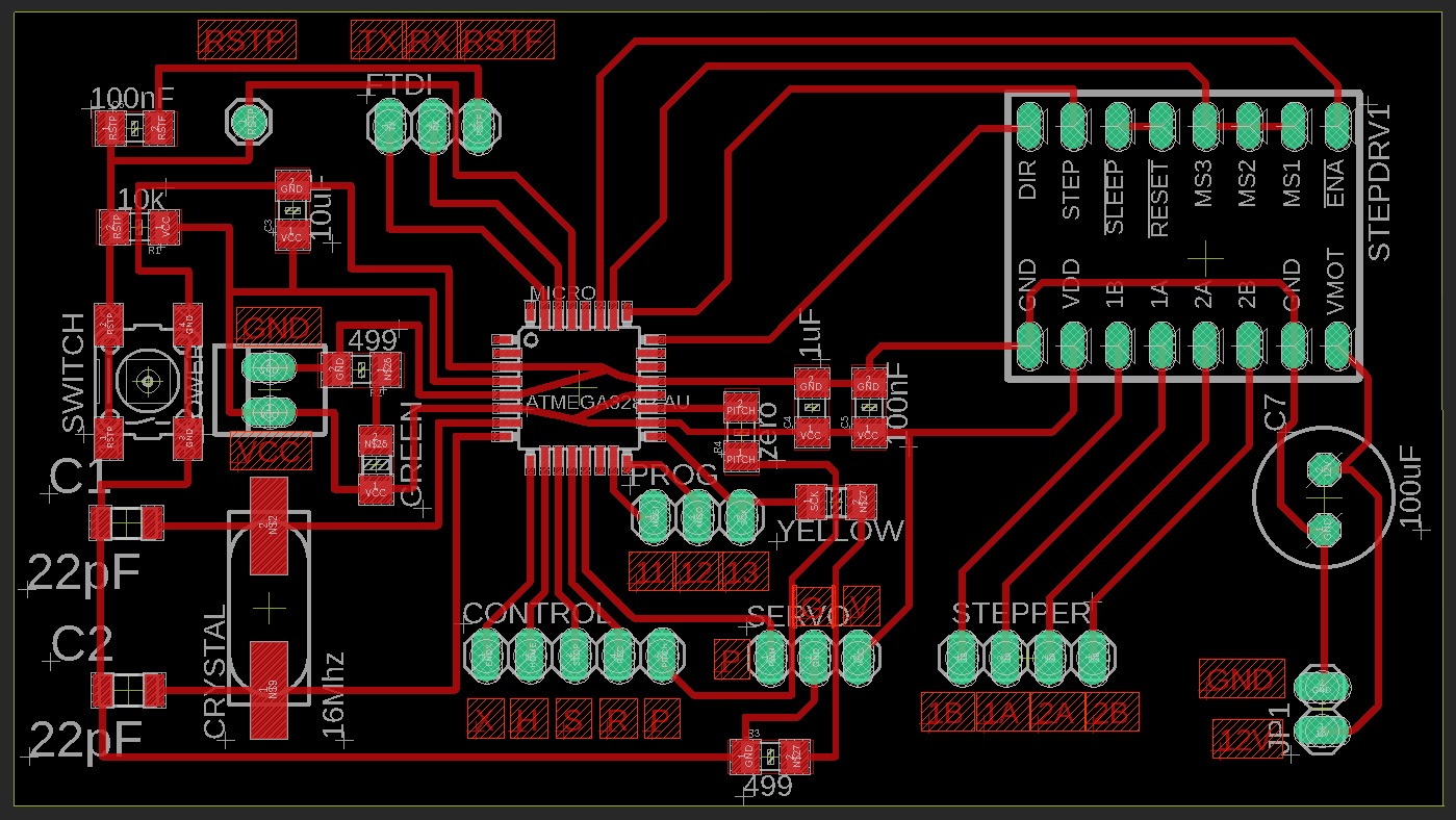
Knowing that my PCB can work as expected, I then redesigned it in Eagle to make a second version without all the errors I had made for the 1st one.
I also decided to introduce back the reset push button and the yellow led from the Satshakit that I had removed on the 1st version.
And I also added one connection to control the stepper driver ENABLE pin.
This will allow me to enable or disable the stepper driver by code if needed (in the home position for example).
Here is the second version of my PCB (schematic and board):
And here is a photo of the final PCB:
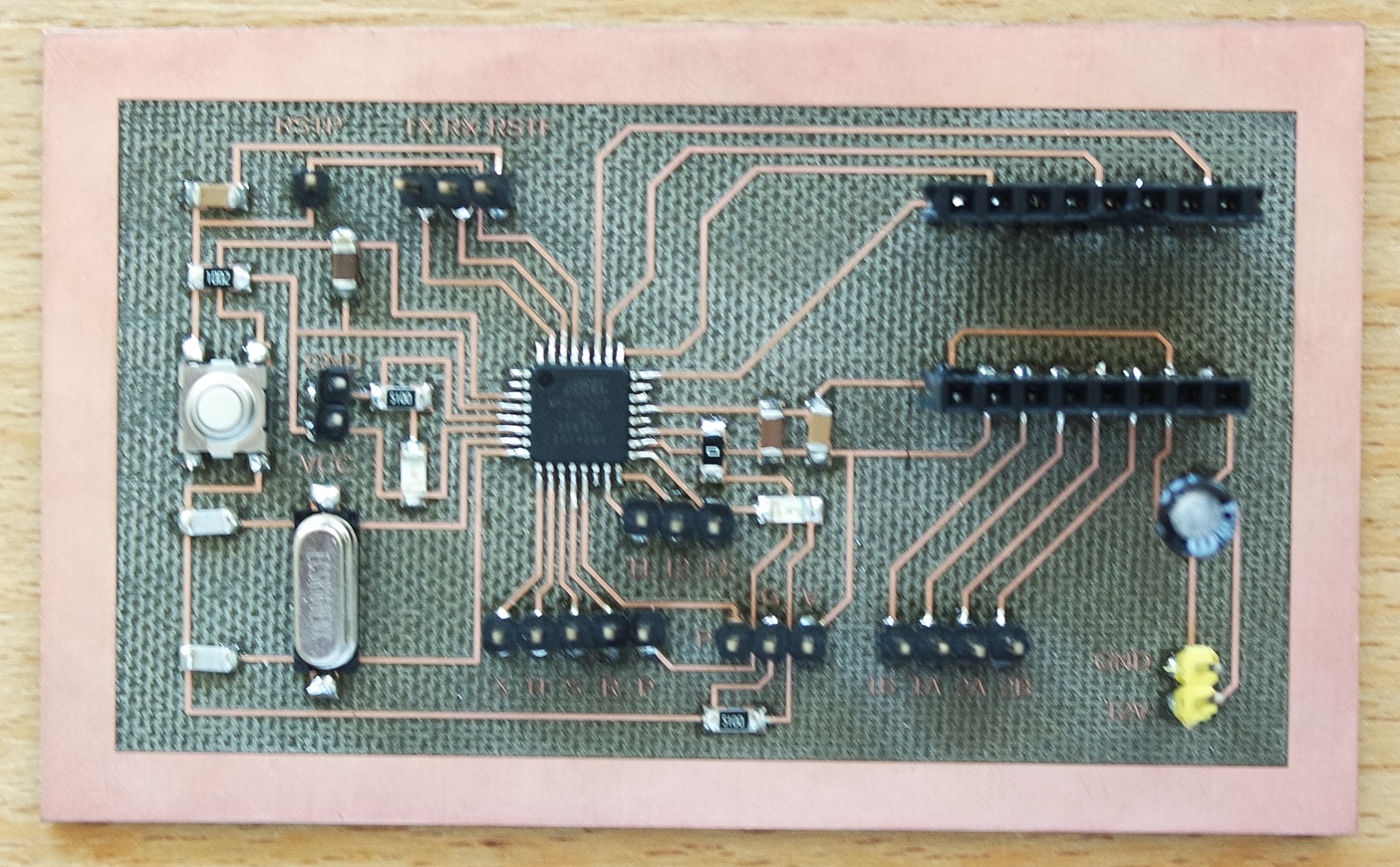
This time burning the bootloader wasn't a problem anymore:
Then I replaced the Satshakit with my own PCB, reworked my code (not using the same pins anymore) and loaded my sketch without any problem:
My machine is now working again but this time using my own PCB design.
I must admit that I was quiet unhappy that I had to make a new PCB to fullfill the requirements instead of going on holydays.
But doing so was a good exercice that teached me new things and I even discovered a error I had done on my Satshakit on week 12 that I had never noticed before because it was working fine.
I had used a capacitor instead of a resistor on the green led. So I also corrected that and the Satshakit is now 100% correct.
Here are the Eagle files and Arduino sketch for my new PCB:
satshakit_Anar_V2.sch
satshakit_Anar_V2.brd
Control_lathe_belt_anarkit_V2.ino

Project files
This work is published under Creative Commons Attribution-ShareAlike 4.0 International License:
Here is my SketchUp file which includes all the parts that I have designed for my project (3D prints, CNC milling, Laser cutting, etc.): proto11.skp
Fusion 360 CNC milling: Lathe_table.f3d
Here is my SketchUp file for the needle holder with two different angles (cutting angle and embossing angle): Needle_holder.skp
And here are my Eagle files and Arduino sketch:
L293D.sch
L293D.brd
w18_button.sch
w18_button.brd
Control_lathe_v2.ino