Computer controlled machining
The group assignement for this week is to test runout, alignment, speeds, feeds, and toolpaths for our machine.
And the individual assignment is to design, mill and assemble something big.
to be used for the photogrammetry lightstage I introduced on week 5. I started to design the different needed connectors that will have to be cut:
They've been designed to be connected with PVC tubes.
As this project could be made faster with a lasercutter, I decided to keep for later and started something new and better adapted to milling.
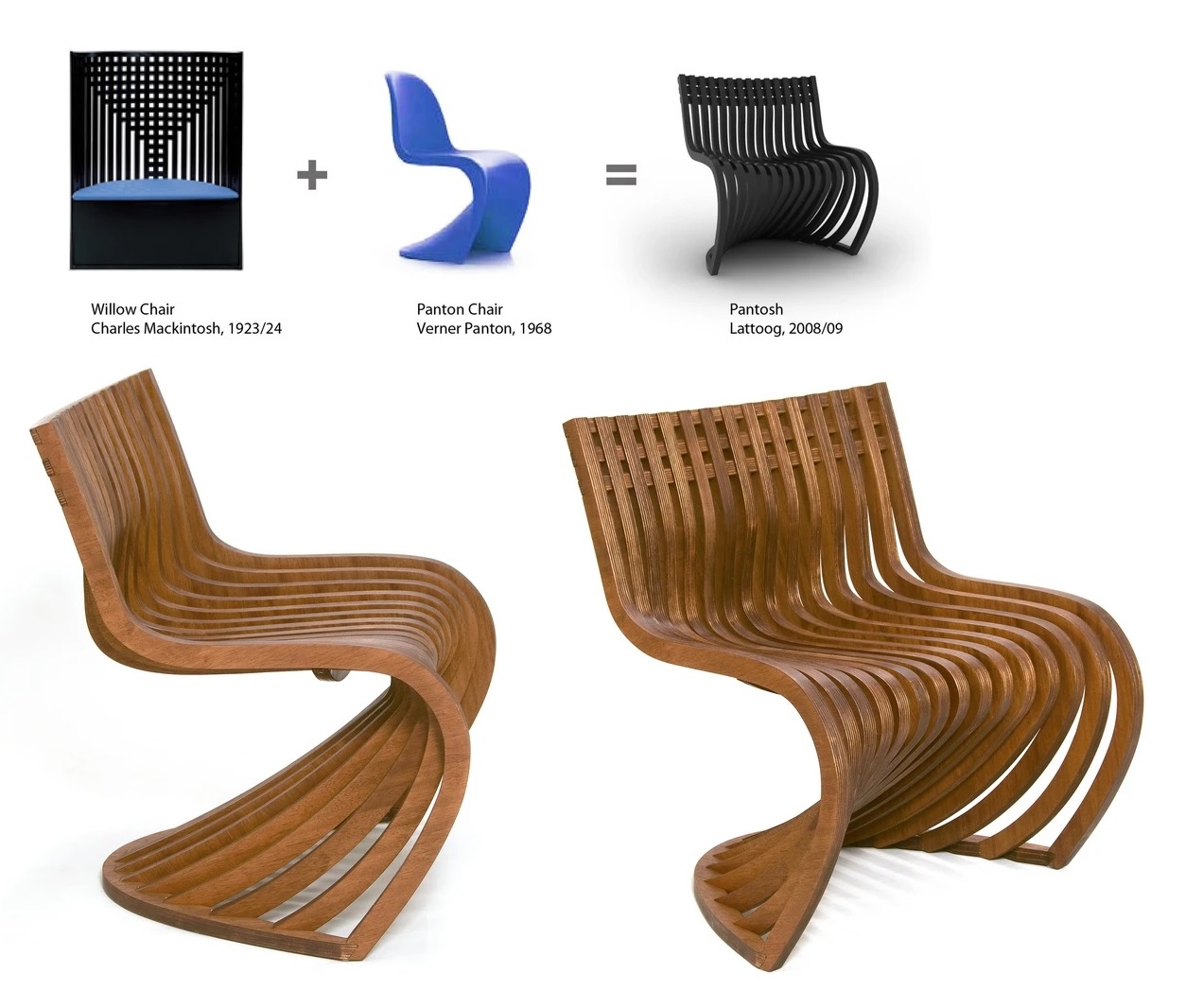
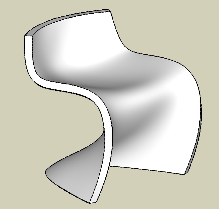
This is what the Pantosh chair looks like:
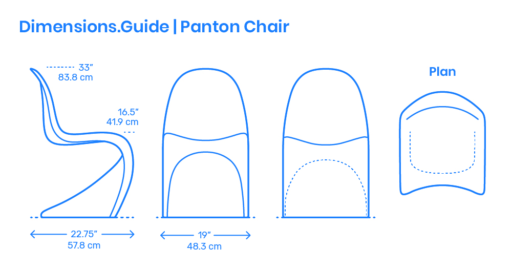
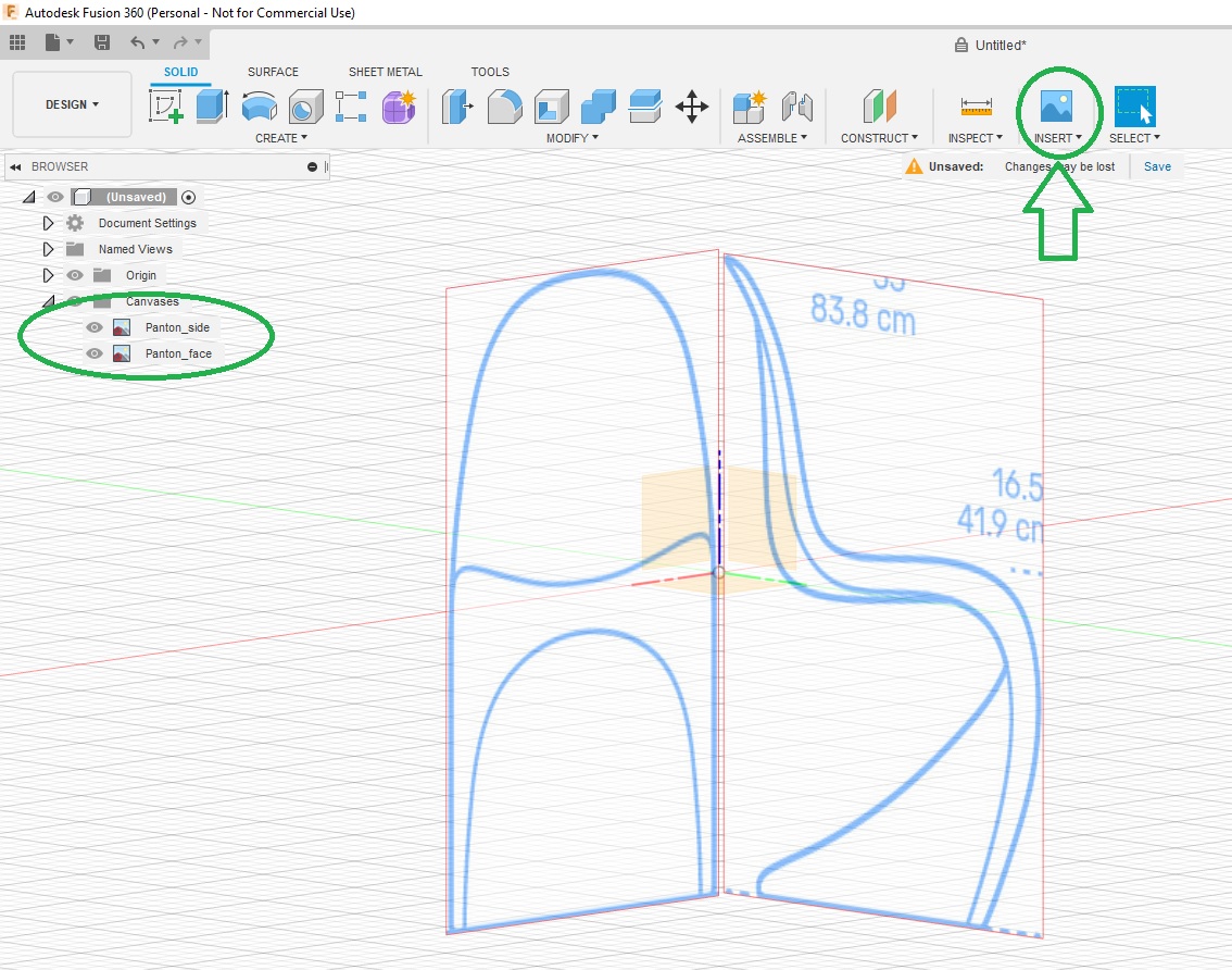
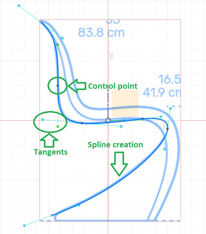
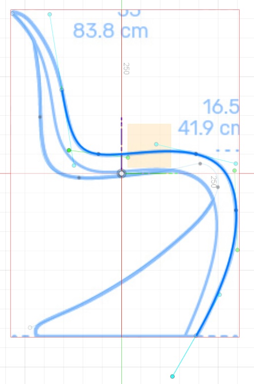
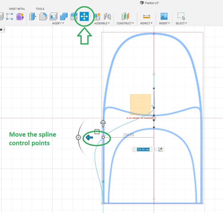
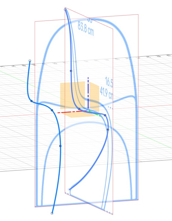
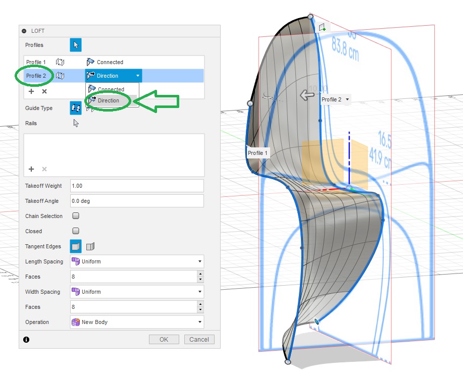
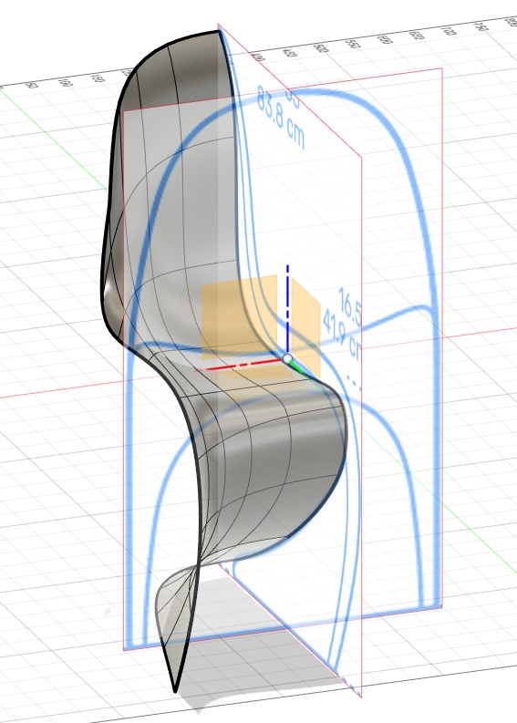
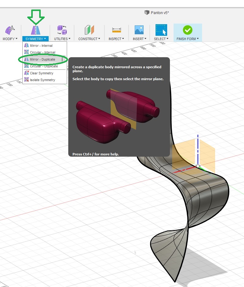
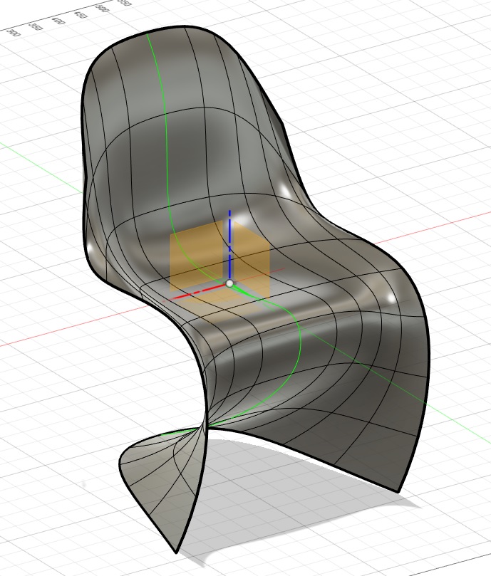
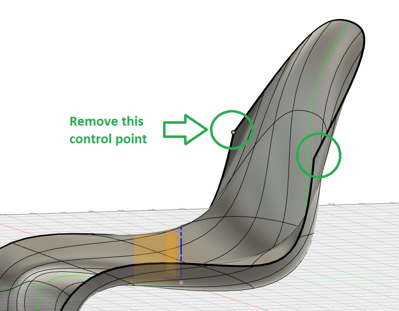
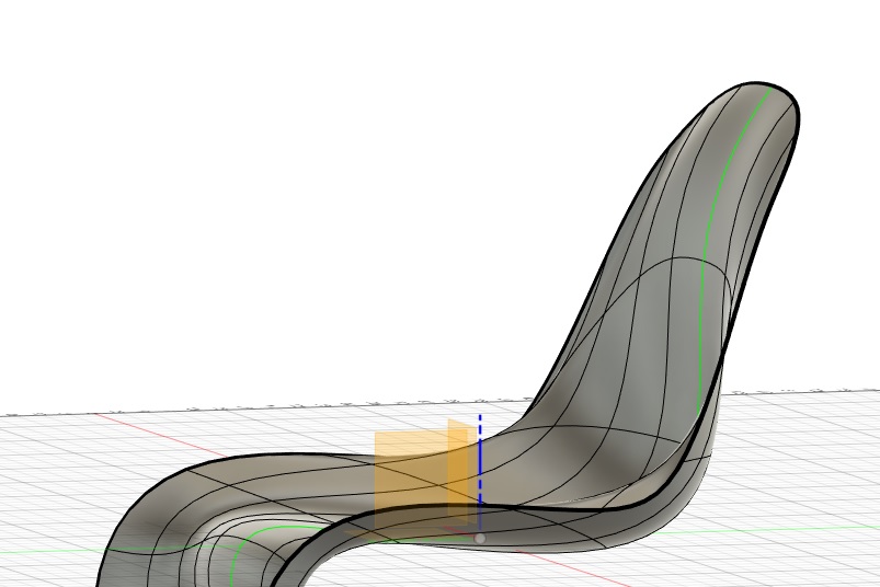
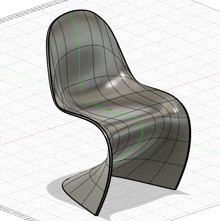
I started to design an original Panton chair first in Fusion 360:
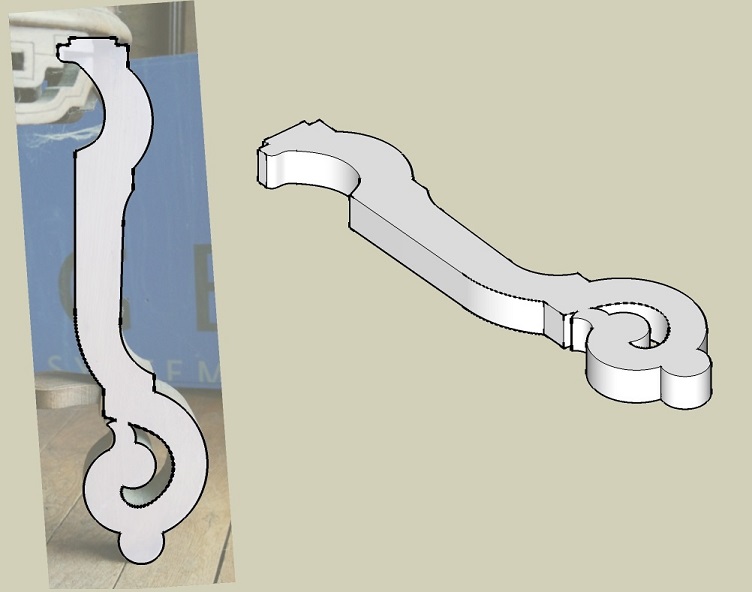
I started by taking pictures of it to help designing it back and started a new modeling:
So I designed it back based on the photo:
The geodesic sphere could be made with a lasercutter with less time than with milling so I will keep it for another time.
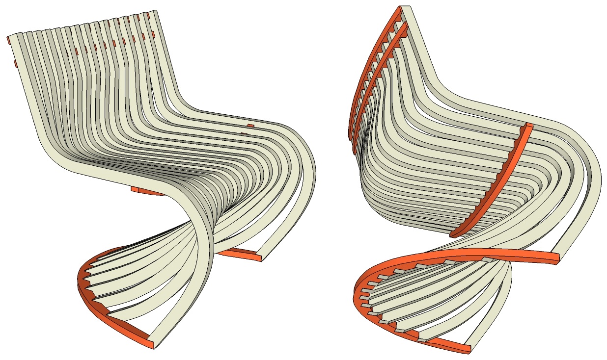
The Pantosh chair is going to take a lot of wood, a lot of stock waste and a lot of time!. So I won't be able to do it for this week.
The wall clock is not that BIG and is a quiet simple milling process that won't show many skills.
For all theses reasons, the small table seems to be the best candidate for this week assignement.
I will use different kind of pathtools to produce my parts:
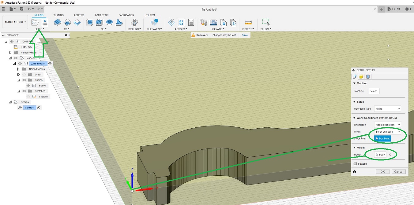
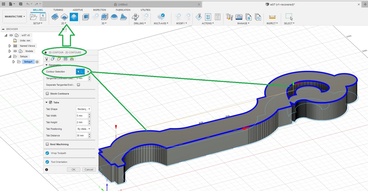
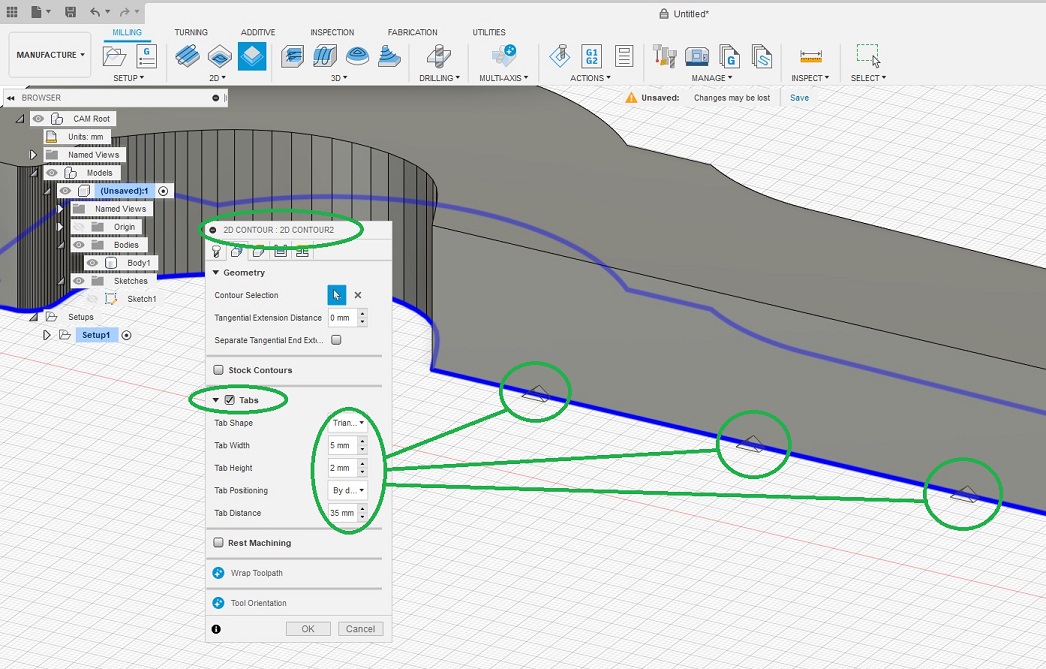
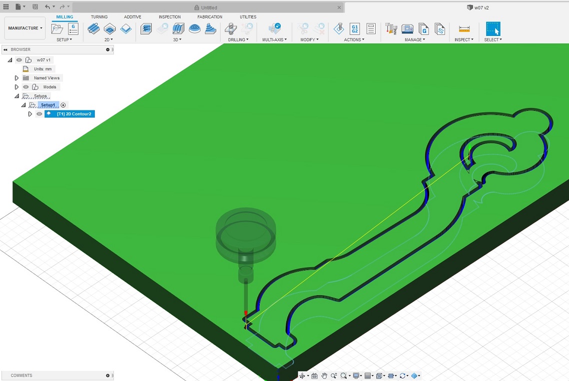
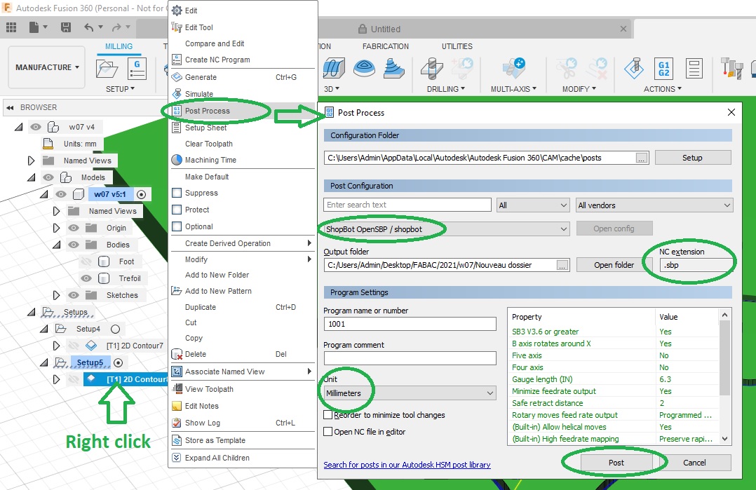
I used Fusion 360 to program the toolpaths and export my gcode:
You will also need to do a homing:
Then you have to define your zero position over your stock. To do so you can use the keypad to manually position the tool head:
Once at the desired position you have to define it as your zero. This can be done by axis:

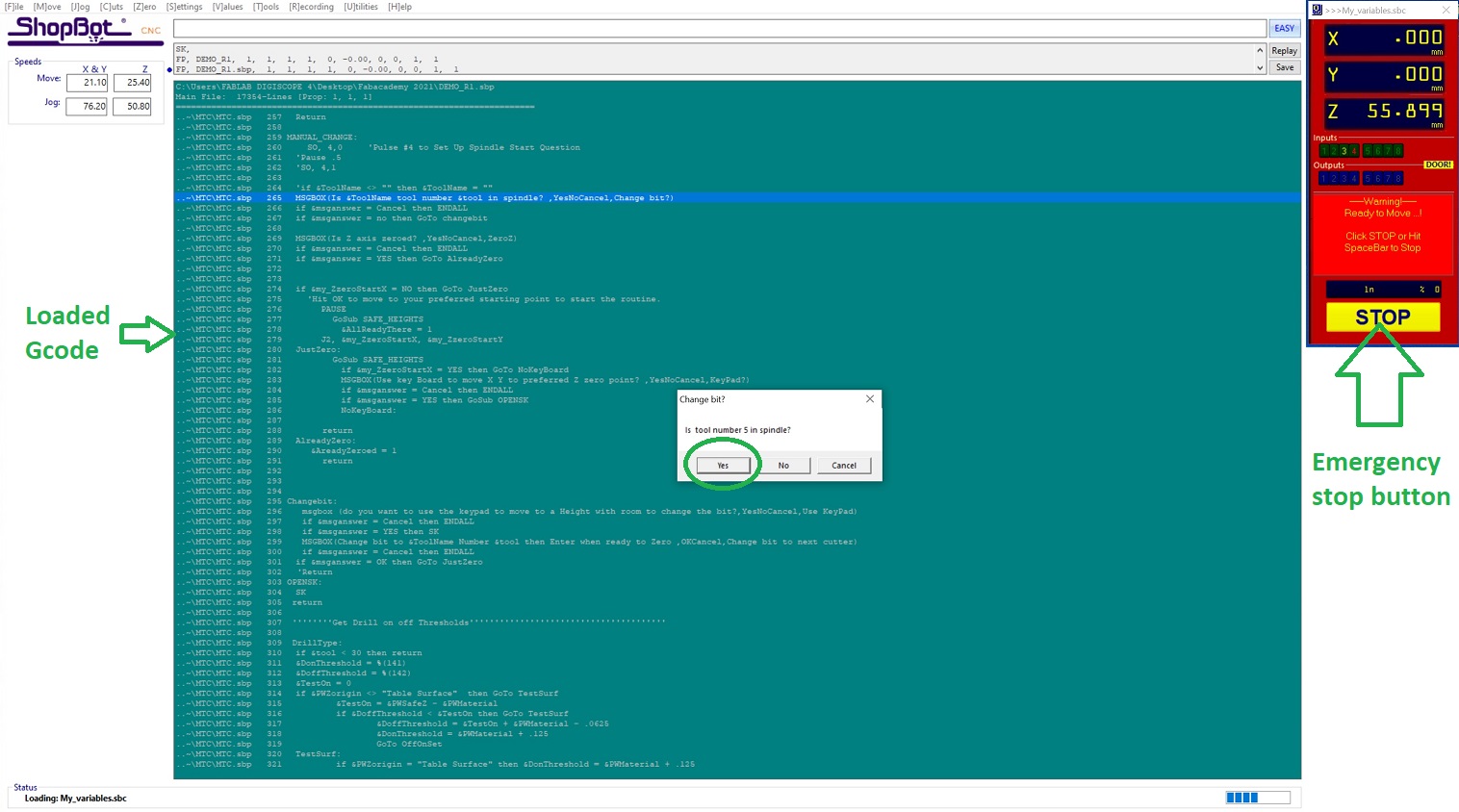
Once everything is set you can then load your Gcode (produced by Fusion 360) and launch your job:
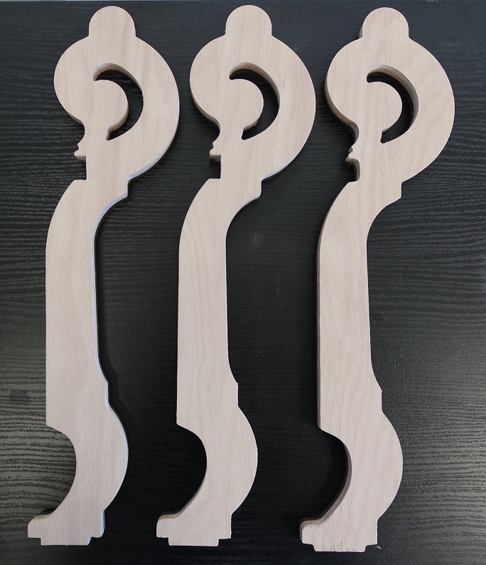
Here are the feet and trifoil plate:
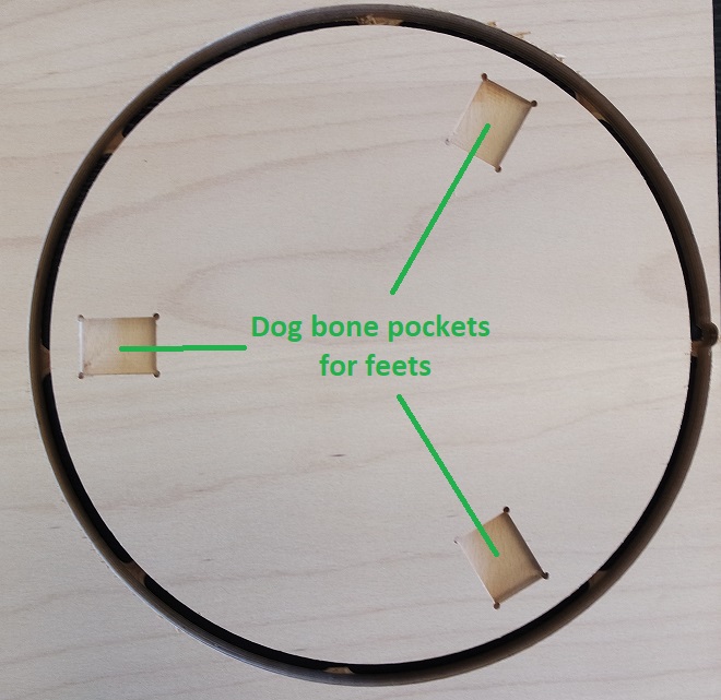
The top plate has dog-bone pockets on one side and 3D milling on the other one which means that at some point I will have to revert it back and be able to register it.
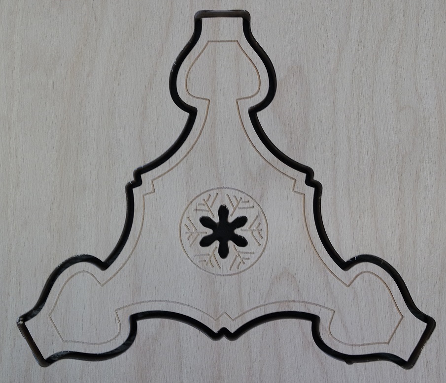
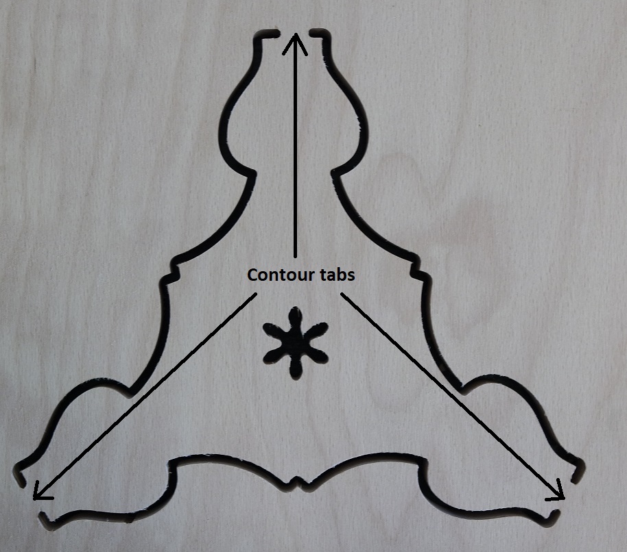
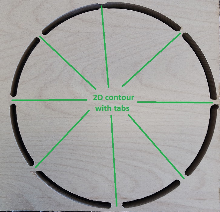
I decided to do the pockets first and then cut the contour:
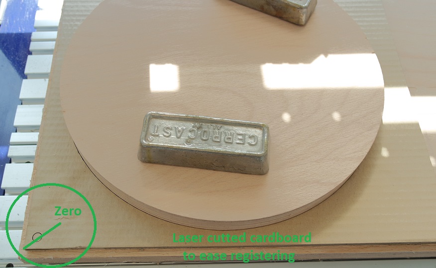
I then used the lasercutter to cut a template in cardboard (relative to my CAD origin) for registering the rounded stock once reverted:
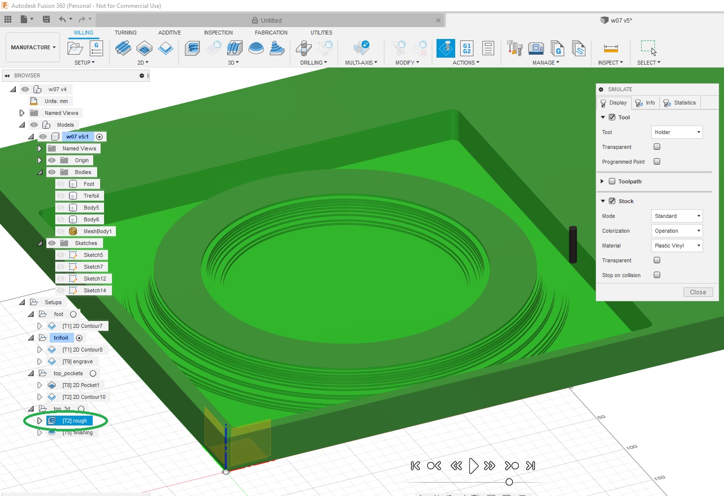
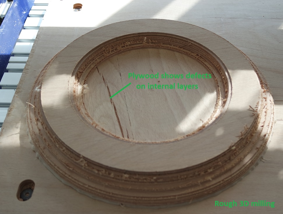
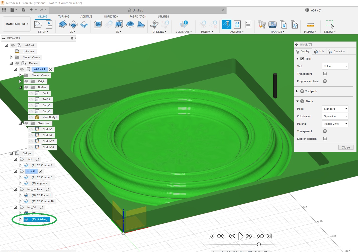
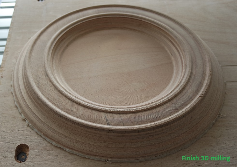
I was then able to do a 3D rough milling followed by a finishing one:
w07_clock.skp
w07_Panton2 v3.f3d
w07_Pantosh.skp
w07_porte_pot05.skp
w07_milling.f3d
And the individual assignment is to design, mill and assemble something big.
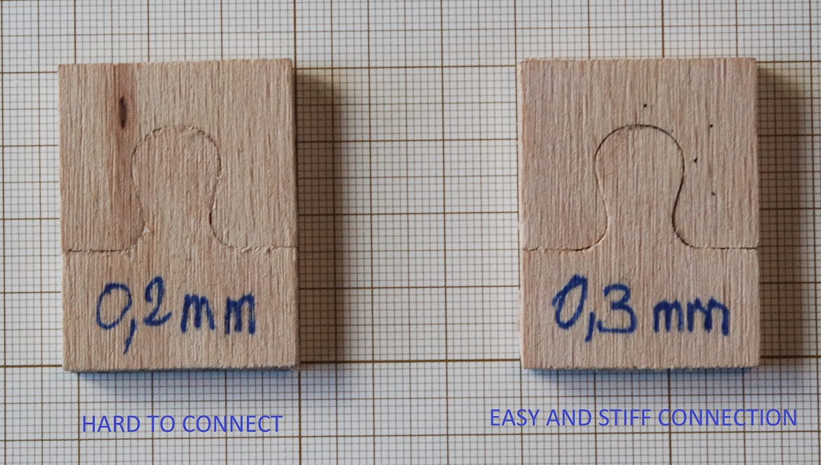
Clearance testing
During our group assignment we tested the minimum clearance needed between two connecting parts and found out that a 0.3mm clearance was a good value:Make something BIG
Research and designs
I had several ideas so I designed a few projects for this week:- a geodesic sphere
- a Pantosh chair
- a small antique table
- a wall clock
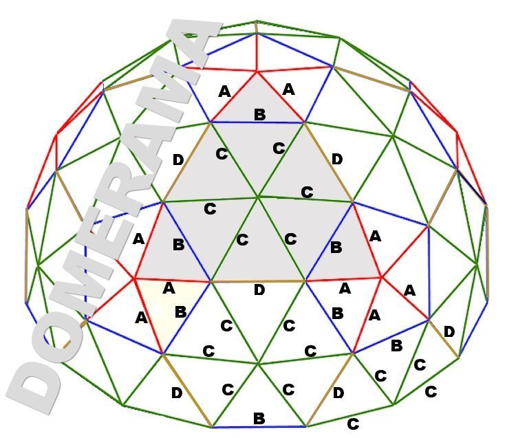
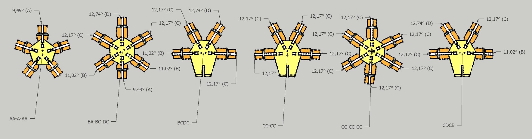
Geodesic sphere
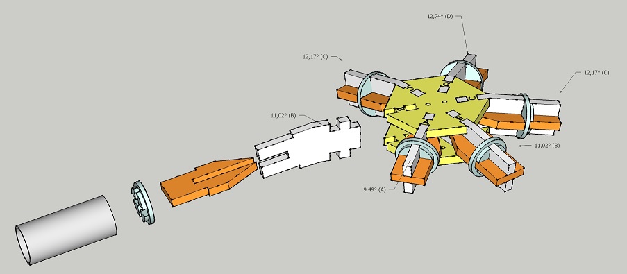
My last year plan as a continuing student, was to build a 3V 5/9 Kruschke geodesic sphere to be used for the photogrammetry light stage introduced earlier in week 5.to be used for the photogrammetry lightstage I introduced on week 5. I started to design the different needed connectors that will have to be cut:
They've been designed to be connected with PVC tubes.
As this project could be made faster with a lasercutter, I decided to keep for later and started something new and better adapted to milling.
Pantosh chair
I decided to make a replica of a Pantosh chair which is a mix between the famous Verner Panton chair (1968) and a Poltrona Willow chair ((1923) from designer Charles R. Mackintosh.This is what the Pantosh chair looks like:
I started to design an original Panton chair first in Fusion 360:
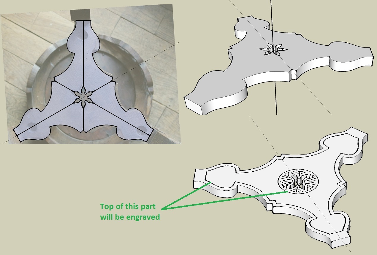
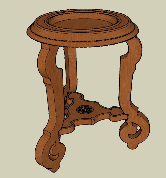
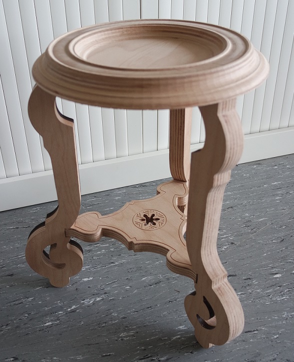
Small table
For this other project I decided to reproduce a small antique table I have at home and that I use to put plants on it.I started by taking pictures of it to help designing it back and started a new modeling:
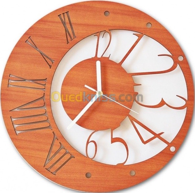
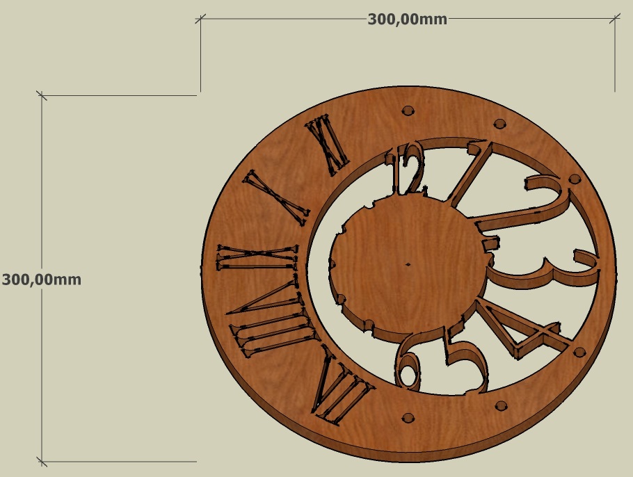
Wall clock
When searching for ideas I found this photo of a wall clock that has a nice design.So I designed it back based on the photo:
Milling process
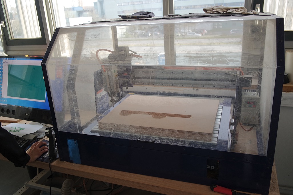
The milling machine we have is a Shopbot whose bed size is 610mm X 460mm.
Design choice
Having four project for this week is too much and I have to make my choice.The geodesic sphere could be made with a lasercutter with less time than with milling so I will keep it for another time.
The Pantosh chair is going to take a lot of wood, a lot of stock waste and a lot of time!. So I won't be able to do it for this week.
The wall clock is not that BIG and is a quiet simple milling process that won't show many skills.
For all theses reasons, the small table seems to be the best candidate for this week assignement.
Milling preparation
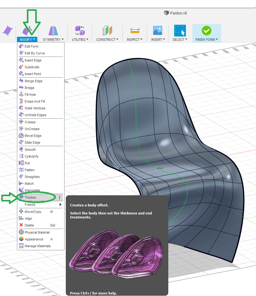
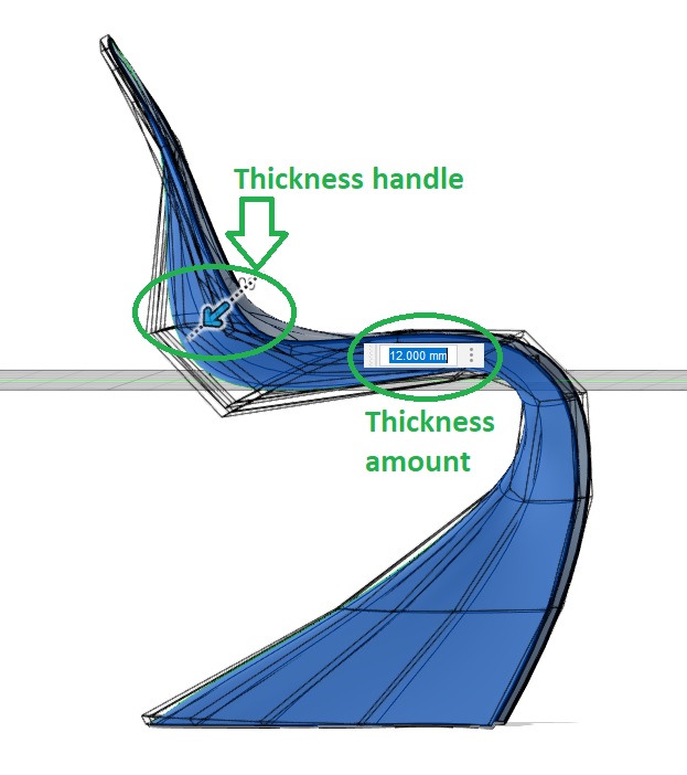
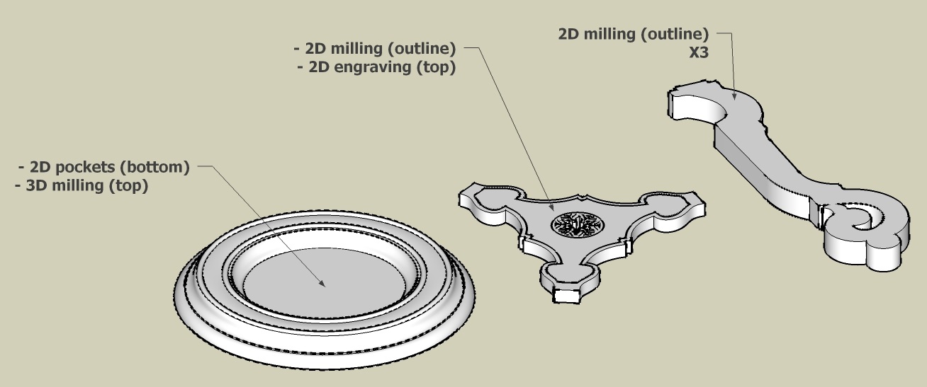
The overall milling project will use two sheets of plywood in 30mm thickness and one in 20mm thickness.I will use different kind of pathtools to produce my parts:
- 2D outline milling
- 2D pockets milling
- 2D engraving
- 3D milling
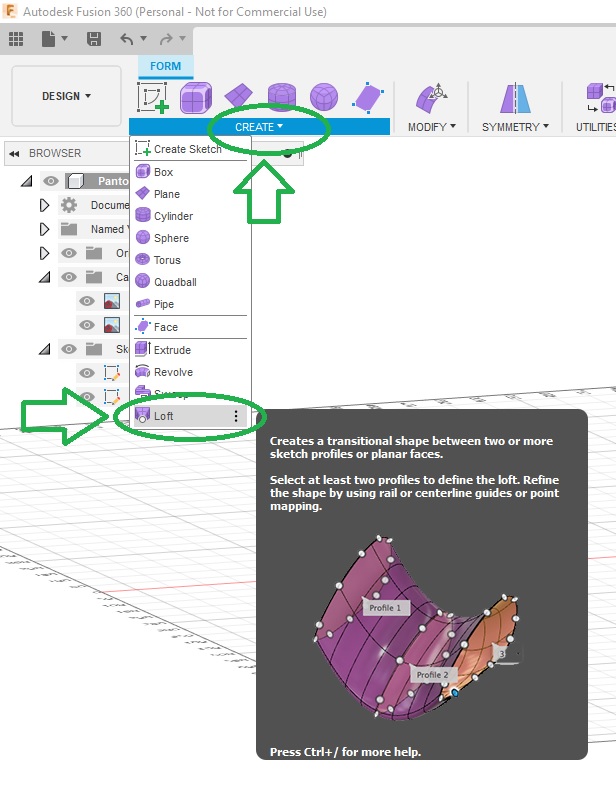
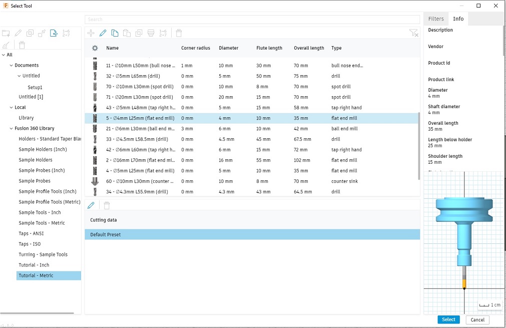
I used Fusion 360 to program the toolpaths and export my gcode:
Milling on the Shopbot
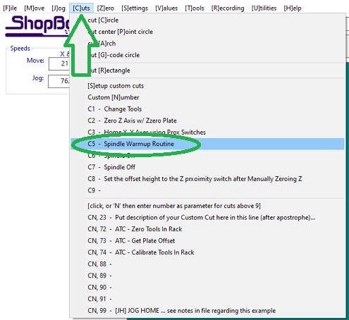
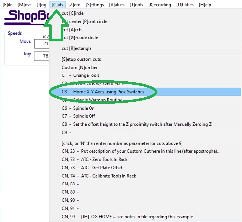
If your the 1st to use the Shopbot it needs to warmed up after turning it on and before to run any job:You will also need to do a homing:
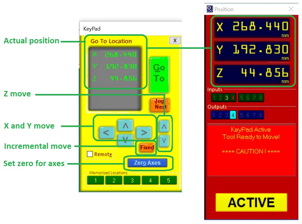
Then you have to define your zero position over your stock. To do so you can use the keypad to manually position the tool head:
Once at the desired position you have to define it as your zero. This can be done by axis:
Once everything is set you can then load your Gcode (produced by Fusion 360) and launch your job:
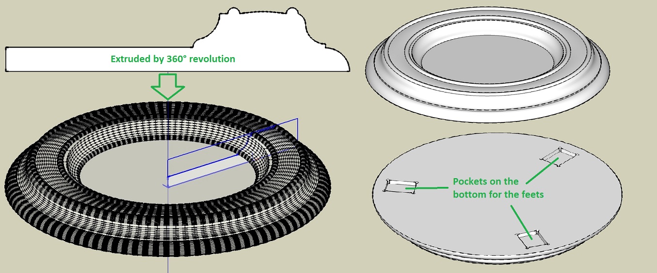
Here are the feet and trifoil plate:
The top plate has dog-bone pockets on one side and 3D milling on the other one which means that at some point I will have to revert it back and be able to register it.
I decided to do the pockets first and then cut the contour:
I then used the lasercutter to cut a template in cardboard (relative to my CAD origin) for registering the rounded stock once reverted:
I was then able to do a 3D rough milling followed by a finishing one:
Assembly and final result
Files for this week
w07_Geodesic.skpw07_clock.skp
w07_Panton2 v3.f3d
w07_Pantosh.skp
w07_porte_pot05.skp
w07_milling.f3d