Output devices
The individual assignment for this week is to add an output device to a microcontroller board we have designed and program it to do something.
And the group assignment is to measure the power consumption of an output device.
As I will need one for my final project, I decided to drive a Nema17 stepper motor.
They are rated at 12V, have 200 steps per revolution, and can rotate at 60 RPM.
There are two types of stepper motors: unipolar and bipolar. Unipolar motors have 5 or 6 wires while bipolar motors will have either 4, 6 or 8 wires.
The Nema17 I will be using is a bipolar stepper (4 wires). Here is a list of links with usefull informations concerning stepper motors:
For example a L293D IC has two H-Bridges it can be used to control a stepper motor. Each H-Bridge can drive one of the electromagnetic coils of the stepper.
By energizing these coils in a specific sequence, the motor can be turned clockwise or counter-clockwise precisely.
The L293D can drive either unipolar or bipolar stepper motors.
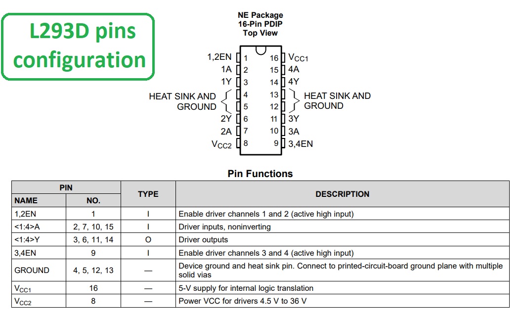
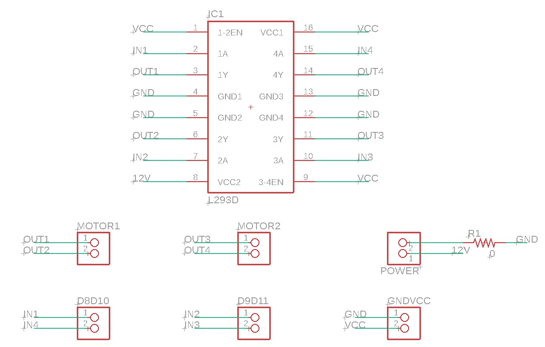
This is the L293D chip pins configuration:
I used an Arduino Uno and did this circuit with a breadboard (here simulated in Tinkercad):
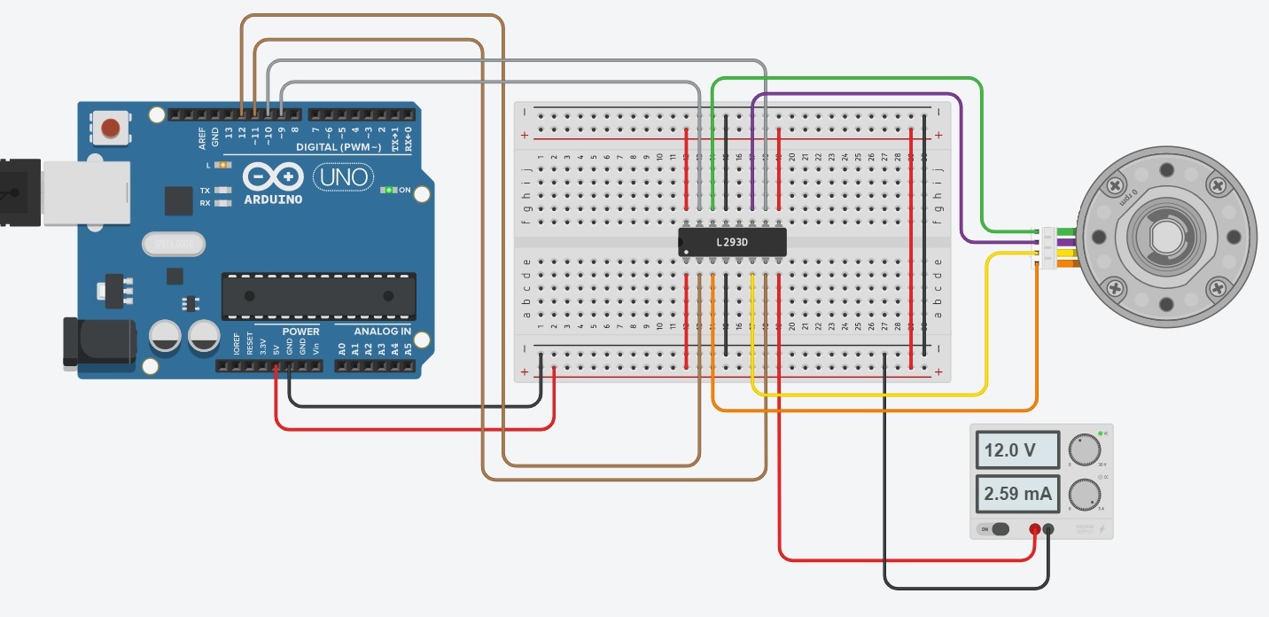
A 12V power supply is connected to Vcc2 (pin 16) and the 5V output from the Arduino to Vcc1 (pin 8).
Pins 4 and 13 are connected to ground.
Pins 1,2EN (1) and 3,4EN (9) are connected to 5V output (the motor is always enabled).
And the driver input pins (1A, 2A, 3A and 4A) are connected onto four Arduino digital output pins (12, 11, 10 and 9). Then the motor wires A+ (Red), A- (Green), B+ (Blue), and B- (Yellow) are connected to the L293D’s output pins (1Y, 2Y, 3Y and 4Y).
You can refer to the Tinkercad illustration above.
Here is the Arduino sketch I used to test my cicuit:
Once the sketch is uploaded on the Arduino and the power supply turned on, the stepper motor starts to rotate as intended in the code:
This board uses:
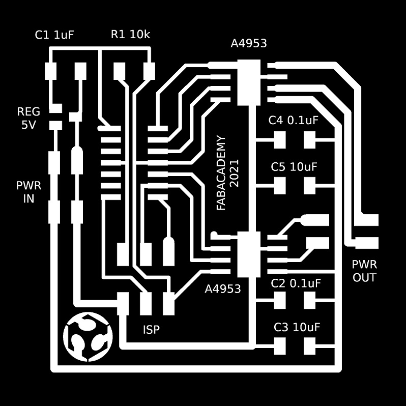
Then I exported the traces in hi-res black and white png image for laser engraving:
So I had to change my plan...
As I already successfuly tested the L293D on a breadboard with an Arduino, I decided to use it instead of the A4950.
And to use a ATmega328 in place of the ATtiny44.
By doing some research I found out that maybe the easiest would be to design just a simple L293D motor driver board that could be connected to either an Arduino or a Fabkit or Satchakit.
I hadn't heard about Fabkit or Satchakit boards designs before. Unless I think I would have taken this route in the previous weeks...
So that's the idea: I'm gonna make a Satchakit that will probably be very usefull for the next coming weeks and my final project, and a very simple L293D motor driver board that will connect to it.
So I returned at designing my L293D motor driver board first. I will then make myself a Satchakit board if I have some time left (or more probably at the beginning of next week).
I will still be able to use it on an Arduino in the meantime...
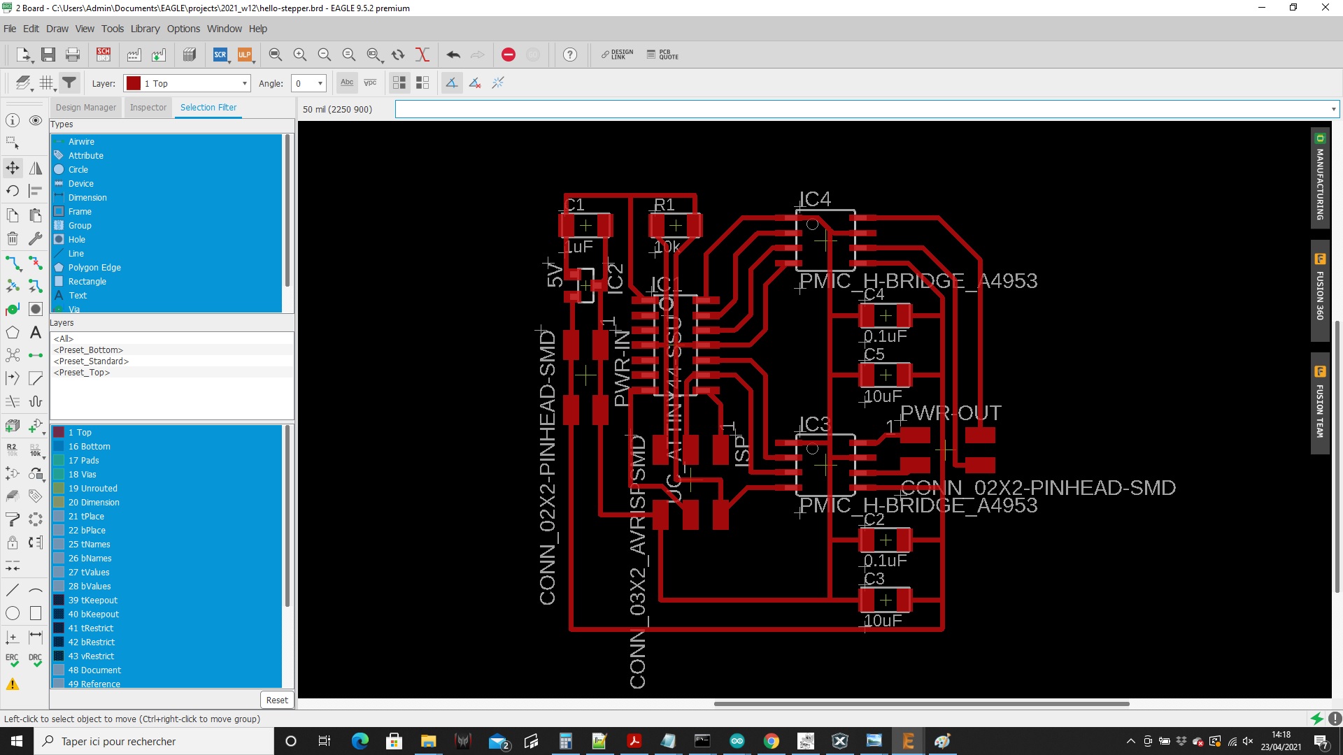
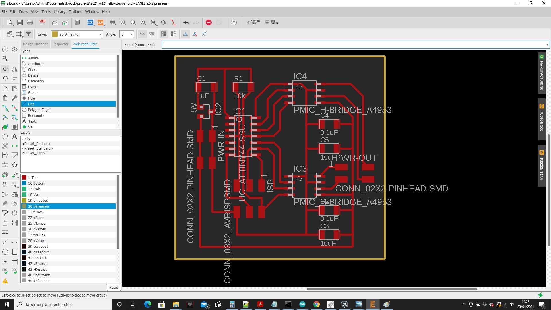
Here are my Eagle schematic and board design:
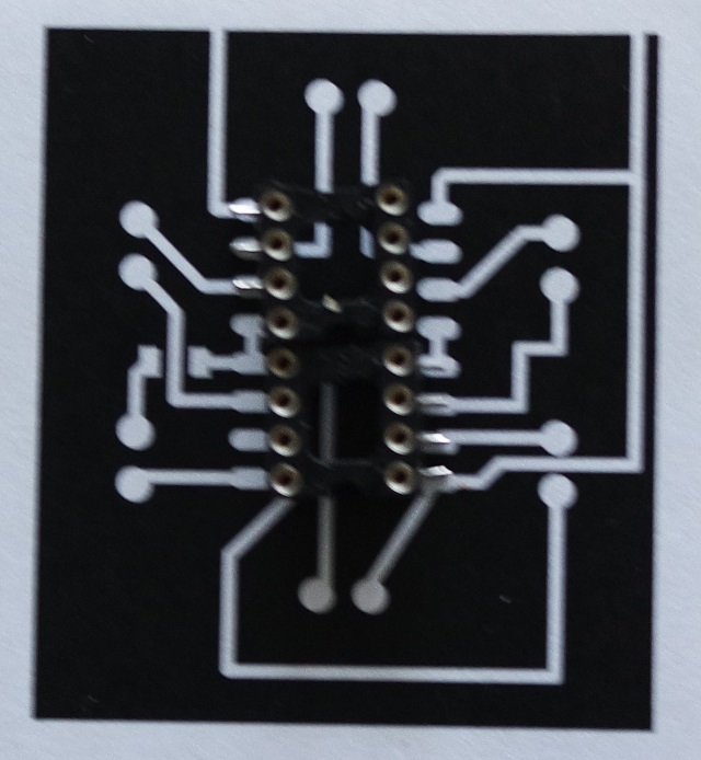
And here is the result of my engraved PCB:
I think my traces are too big and I will realise later that the footprint for the L293D is not good...
Before starting soldering I picked all the components needed:
But once again I had a bad surprise. The L293D I had was a thru-hole version while I designed my board for a SMD footprint...
I should have check that before engraving. My fault.
As a solution, I used one of these:
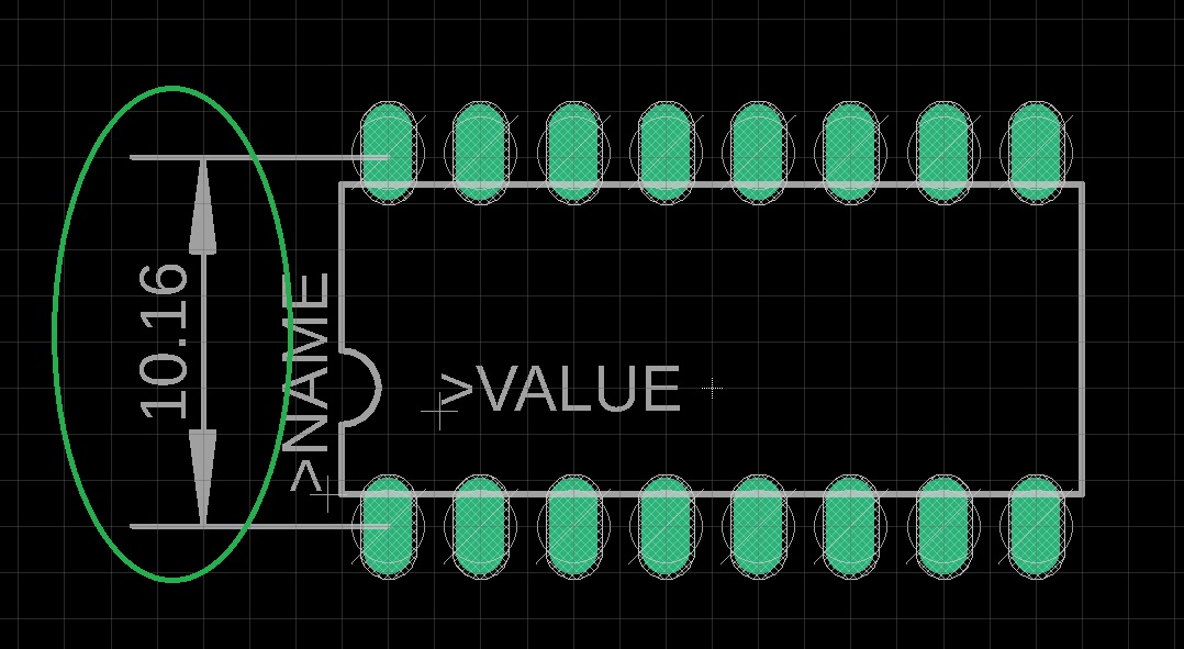
So I had to modify the footprint of the L293D device in Eagle to adapt its width.
But this time I printed it on paper before engraving it again just to make sure:
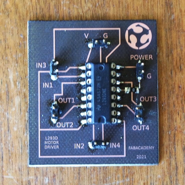
And here is the finished board:
The programming step had already been done when I tried the L293D on a breadboard, and all I had to do is reuse the same Arduino sketch.
The motor rotates as intended in the code:
Now the next step is to make my Satchakit board.
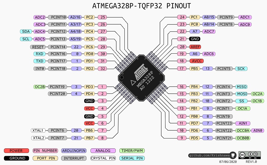
These are the pins description for the ATmega328P:
And here is the result of my laser engraving process:
But our instructor Jonah gave me good advices on where to start and how to proceed and I was suprised I could do it.
Here is my Satshakit finished and ready for testing:
Here are the different steps for that procedure:
Once the fuses are set I can now program my Satshakit board by uploading my sketch to it.
This can be done by using an USB-to-Serial converter cable and here is how it should be connected:
And I'm glad to see that everything works as expected:
L293D.brd
hello-stepper.sch
hello-stepper.brd
And the group assignment is to measure the power consumption of an output device.
Type of output devices
There are several output devices that can be used:- motors (DC / BLDC / Stepper / Servo)
- LED (RGB / array)
- display (LCD / OLED / TFT)
- speakers
Group assignment
During our group assignment we analyzed the current consumption of several electronic components with a graphical multimeter.Individual assignment
I have to design a board that will drive an output device of my choice.As I will need one for my final project, I decided to drive a Nema17 stepper motor.
They are rated at 12V, have 200 steps per revolution, and can rotate at 60 RPM.
About stepper motors
Stepper motors are used when precision is needed.There are two types of stepper motors: unipolar and bipolar. Unipolar motors have 5 or 6 wires while bipolar motors will have either 4, 6 or 8 wires.
The Nema17 I will be using is a bipolar stepper (4 wires). Here is a list of links with usefull informations concerning stepper motors:
- How Electric Motors Work
- Stepper Motor Connections
- Bipolar Stepper Motor and Control
- Stepper Motor with Microcontrollers
Stepper motor driver
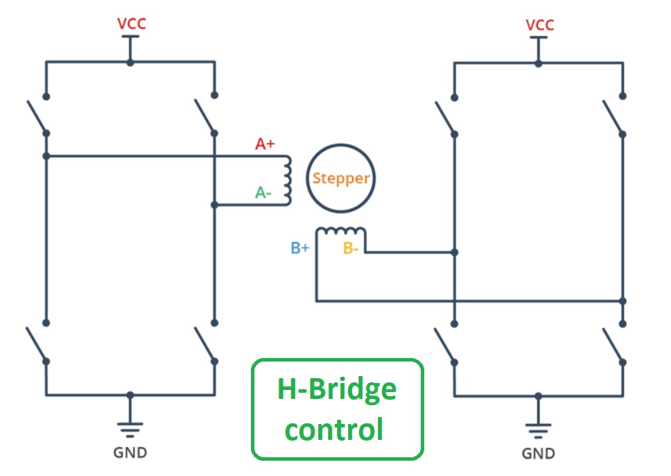
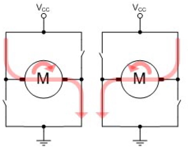
A stepper motor can be controlled with H-bridge. It allows to control the direction in which the motor turns. This image illustrates it:For example a L293D IC has two H-Bridges it can be used to control a stepper motor. Each H-Bridge can drive one of the electromagnetic coils of the stepper.
By energizing these coils in a specific sequence, the motor can be turned clockwise or counter-clockwise precisely.
The L293D can drive either unipolar or bipolar stepper motors.
Arduino simulation
Before to dive into my board design, I wanted to test the L293D with my Nema17 first.This is the L293D chip pins configuration:
I used an Arduino Uno and did this circuit with a breadboard (here simulated in Tinkercad):
A 12V power supply is connected to Vcc2 (pin 16) and the 5V output from the Arduino to Vcc1 (pin 8).
Pins 4 and 13 are connected to ground.
Pins 1,2EN (1) and 3,4EN (9) are connected to 5V output (the motor is always enabled).
And the driver input pins (1A, 2A, 3A and 4A) are connected onto four Arduino digital output pins (12, 11, 10 and 9). Then the motor wires A+ (Red), A- (Green), B+ (Blue), and B- (Yellow) are connected to the L293D’s output pins (1Y, 2Y, 3Y and 4Y).
You can refer to the Tinkercad illustration above.
Here is the Arduino sketch I used to test my cicuit:
// Include the Arduino Stepper Library
#include <Stepper.h>

// Number of steps per output rotation (depends on your motor)
const int stepsPerRevolution = 200;

// Create Instance of Stepper library
Stepper myStepper(stepsPerRevolution, 12, 11, 10, 9);

void setup()
{
	// set the speed at 20 rpm
	myStepper.setSpeed(20);
	// initialize the serial port
	Serial.begin(9600);
}

void loop()
{
	// rotate one revolution in one direction
	Serial.println("clockwise");
	myStepper.step(stepsPerRevolution);
	delay(500);

	// rotate one revolution in the other direction
	Serial.println("counterclockwise");
	myStepper.step(-stepsPerRevolution);
	delay(500);
}
Once the sketch is uploaded on the Arduino and the power supply turned on, the stepper motor starts to rotate as intended in the code:
Board design and making
Initially I wanted to replicate Neil's hello.stepper.bipolar.44 board.This board uses:
- 1 x ATTINY44 MICROCONTROLLER
- 2 x 2x2 HEADER (POWER)
- 1 x 3X2 HEADER (AVRISP)
- 2 x CAPACITOR 10 uf
- 1 x CAPACITOR 1 uf
- 2 x CAPACITOR 0.1 uf
- 1 x 10k Ohm RESISTOR
- 1 x 5V REGULATOR
- 2 x A4950 MOTOR DRIVER
Design
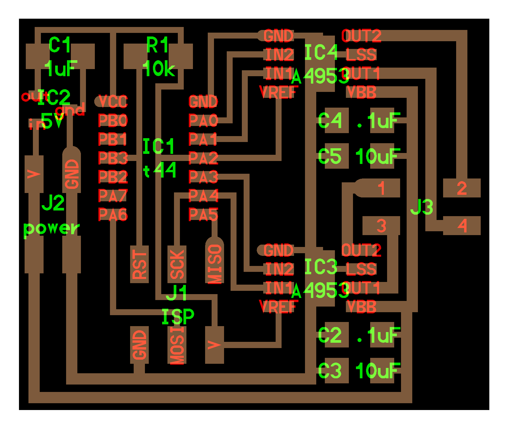
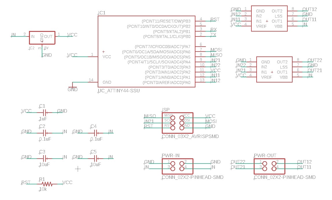
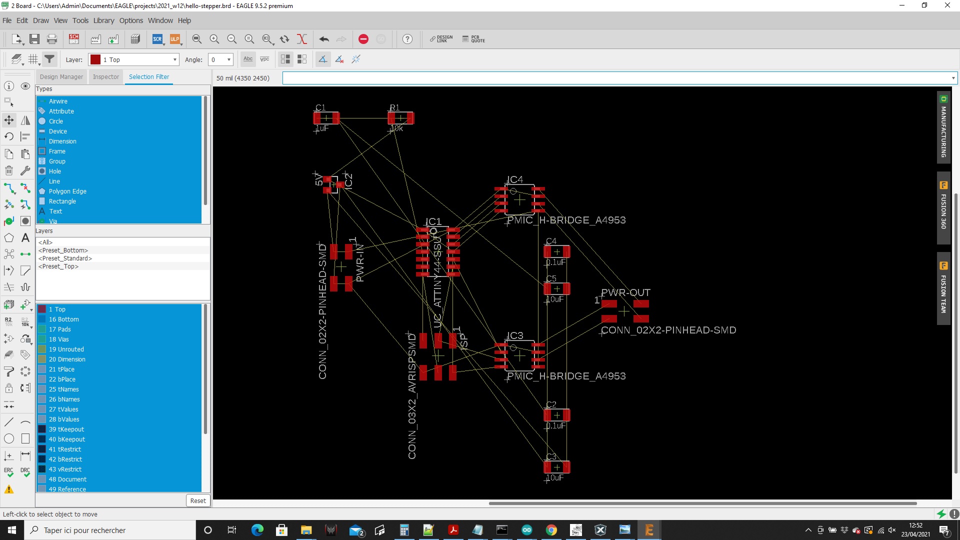
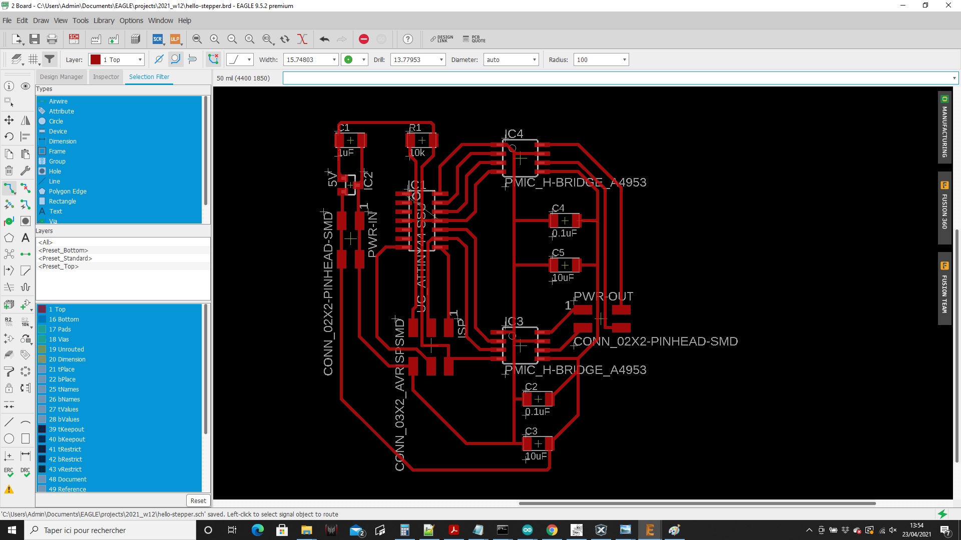
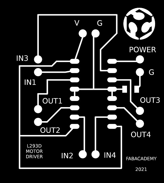
I started to redraw Neil's example. The schematic and board design were made in Eagle:Then I exported the traces in hi-res black and white png image for laser engraving:
Laser engraving aborted - back to Eagle
Unfortunately when I came back to the lab on monday, I figured out that we don't have any A4950 motor driver chip.So I had to change my plan...
As I already successfuly tested the L293D on a breadboard with an Arduino, I decided to use it instead of the A4950.
And to use a ATmega328 in place of the ATtiny44.
By doing some research I found out that maybe the easiest would be to design just a simple L293D motor driver board that could be connected to either an Arduino or a Fabkit or Satchakit.
I hadn't heard about Fabkit or Satchakit boards designs before. Unless I think I would have taken this route in the previous weeks...
So that's the idea: I'm gonna make a Satchakit that will probably be very usefull for the next coming weeks and my final project, and a very simple L293D motor driver board that will connect to it.
So I returned at designing my L293D motor driver board first. I will then make myself a Satchakit board if I have some time left (or more probably at the beginning of next week).
I will still be able to use it on an Arduino in the meantime...
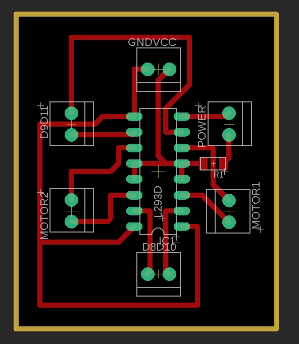
Here are my Eagle schematic and board design:
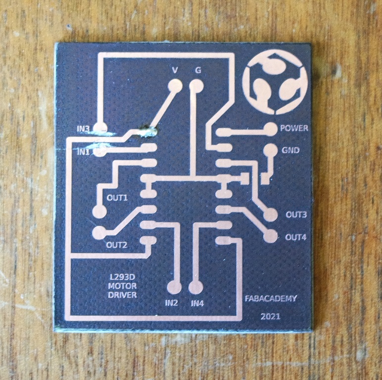
And here is the result of my engraved PCB:
I think my traces are too big and I will realise later that the footprint for the L293D is not good...
Before starting soldering I picked all the components needed:
- 1 x L293D
- 6 x pin 2x1
But once again I had a bad surprise. The L293D I had was a thru-hole version while I designed my board for a SMD footprint...
I should have check that before engraving. My fault.
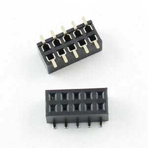
As a solution, I used one of these:
So I had to modify the footprint of the L293D device in Eagle to adapt its width.
But this time I printed it on paper before engraving it again just to make sure:
Soldering
Soldering this board was quiet simple due to the small number and the big size of the components.And here is the finished board:
Board programming
As I haven't yet made my Satchakit board, I used an Arduino Uno again.The programming step had already been done when I tried the L293D on a breadboard, and all I had to do is reuse the same Arduino sketch.
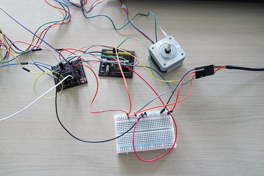
Board testing
After connecting everything and powering the motor driver with a 12V external power supply, I was able to test that it's working fine.The motor rotates as intended in the code:
Now the next step is to make my Satchakit board.
Making of Satchakit
During Fab Academy 2015, Daniele Ingrassia designed the Satchakit which is a Arduino-compatible board.BOM
Here is a list of all the components needed to make a Satchakit board:- 1 x ATMEGA328P-AU
- 1 x CRYSTAL 16Mhz/18pF
- 1 x green LED
- 1 x yellow LED
- 1 x SWITCH
- 1 x 10K resistor
- 2 x 499 resistor
- 2 x 22pF capacitor
- 1 x 10uF capacitor
- 1 x 1uF capacitor
- 2 x 100nF capacitor
- 1 x pin header 1x2
- several pin headers
These are the pins description for the ATmega328P:
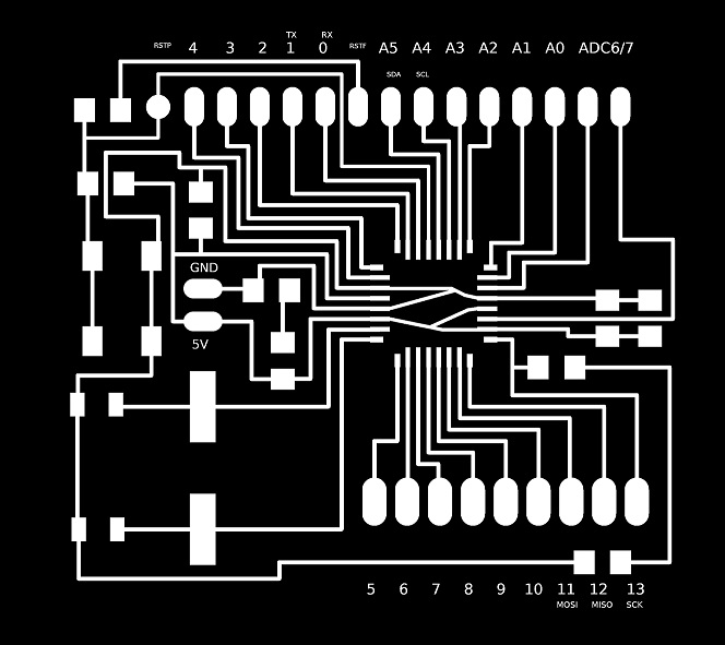
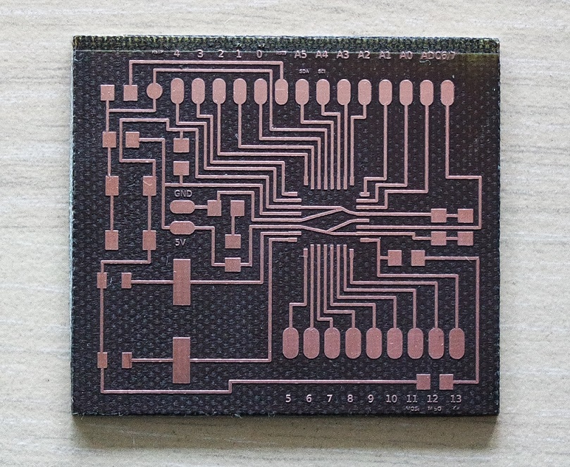
Laser engraving
This is the image I used for laser engraving:And here is the result of my laser engraving process:
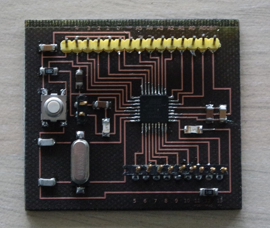
Soldering
I was quiet intimidated at first when I saw how small the ATmega328 microcontroller is.But our instructor Jonah gave me good advices on where to start and how to proceed and I was suprised I could do it.
Here is my Satshakit finished and ready for testing:
Programming
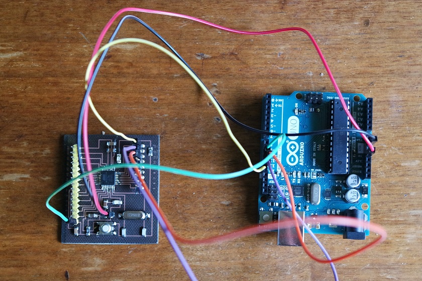
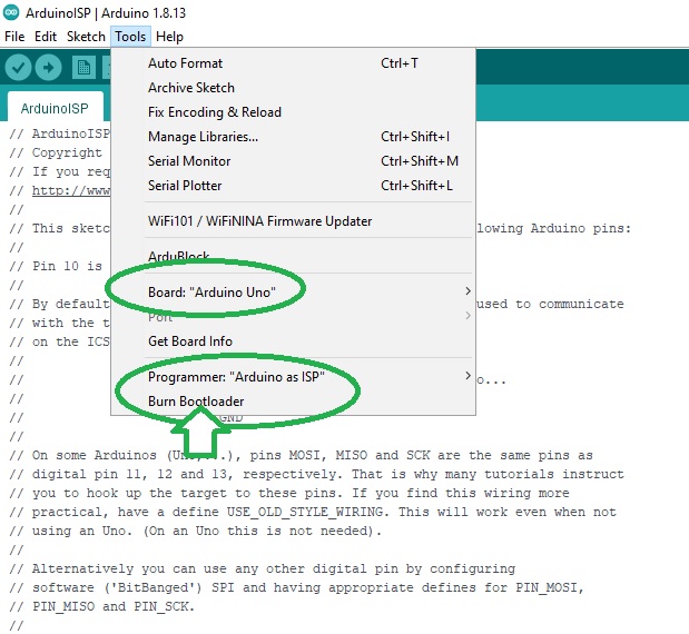
The first thing to do is to set the fuses. It can be done by using the Arduino IDE and burn the bootloader.Here are the different steps for that procedure:
- open Arduino IDE
- connect an Arduino UNO to your PC
- upload the example sketch ArduinoISP
- disconnect the Arduino
- connect the Satshakit to the Arduino (see connections below)
- reconnect the Arduino
- select Arduino as ISP programmer
- select Arduino UNO as the board
- burn the bootloader
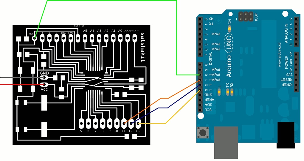
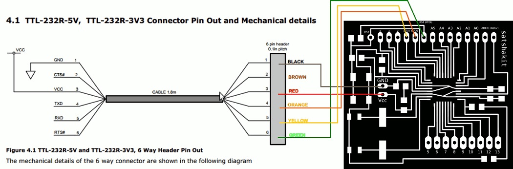
Once the fuses are set I can now program my Satshakit board by uploading my sketch to it.
This can be done by using an USB-to-Serial converter cable and here is how it should be connected:
Testing
Once the sketch is uploaded on the Satchakit I can test if it's working fine.And I'm glad to see that everything works as expected:
Satshakit links
Here is a list of usefull links that helped me on Satshakit:Files for this week
L293D.schL293D.brd
hello-stepper.sch
hello-stepper.brd