Input devices
The individual assignment for this week is to measure something out from a sensor that we must add to a microcontroller board we have designed.
And the group assignment is to probe an input device's analog levels and digital signals.
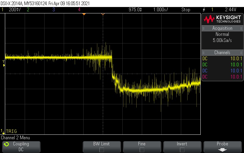
We connected different sensors to an Arduino board one at a time and used the oscilloscope to visualize the signals that was either emmitted or reseived.
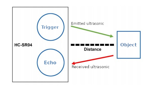
The first sensor's signals we did look at is a ultrasonic distance sensor (sonar). It can be used to measure distances by emmiting ultrasonic and measuring the time it takes for them to come back to the sensor.
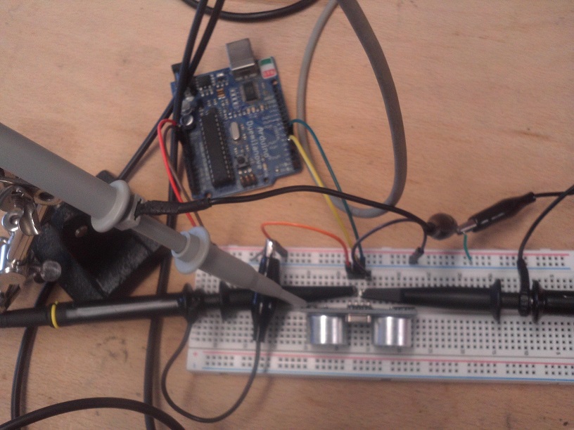
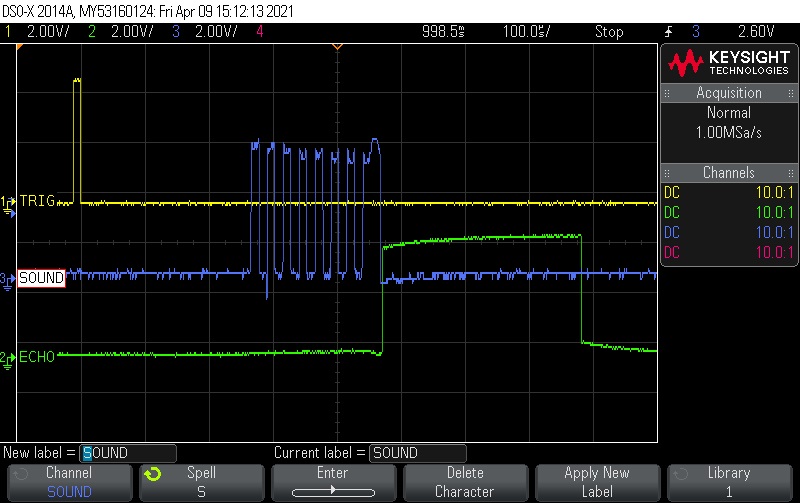
We were able to visualize both the emitting signal or "Triger" (showed in yellow) and the received signal or "Echo" (showed in green).
We even were able to visualize the emitted ultrasonic burst (showed in blue).
The next sensor's signal we looked at was for a bending sensor. The first thing we did was to measure its resistance with a multimeter.
Without bending it we could read a 10k Ohms resistance that dropped down to about 6k Ohms when bended.
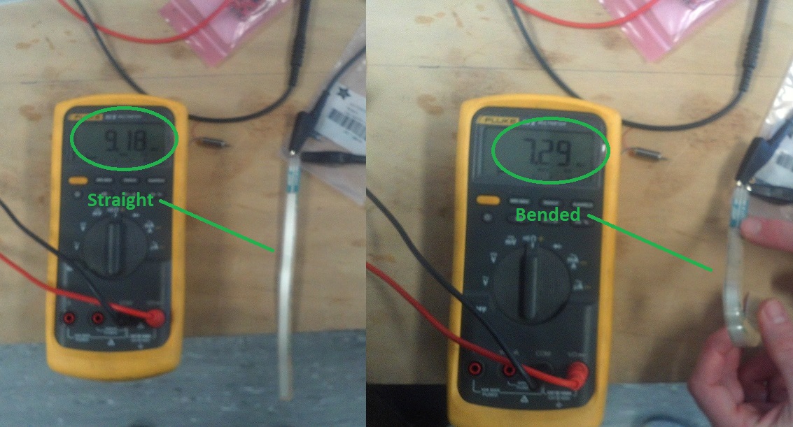
So it's a resistor variable device. As only tension signals (voltage) can be displayed on a osciloscope we used a voltage divider circuit to visualize the sensor's signals variations.
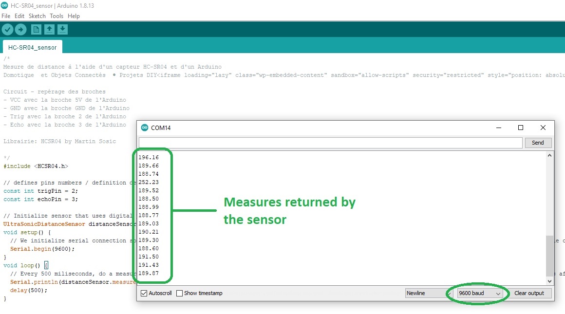
After installing the HCSR04 library, I wrote some simple code to read out the signals and display them on the monitor.
And here are the measured distance returned by the sensor:
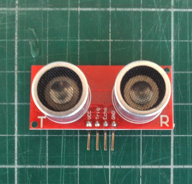
It has 4 pins labeled: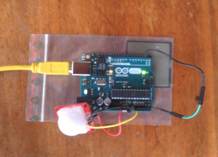
Here is the Arduino sketch I used (the sketch is from this tutorial):
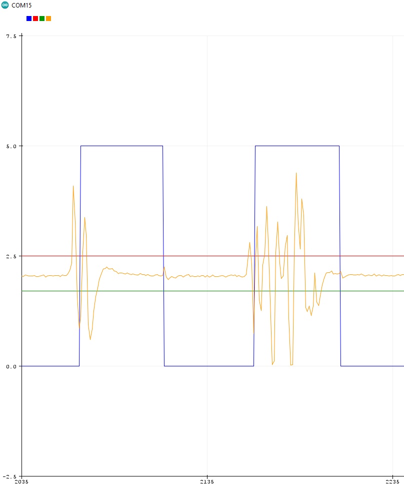
And here is what the Arduino IDE's visual plotter shows. Orange is the analog signals that triggers if it exceed the upper and lower thresholds (Red and Green lines). The digital signal is shown in Blue:
As the force on the sensor increases or decreases it varies the resistance. So it's very similar to the fexible bending sensor we used in the group assignment.
The more you push on the sensor, the lower the resistance will be.
Combined with a resistor to make a voltage divider we can have a variable voltage.
I used a 4.7k Ohms resistor.
Here is the Arduino sketch I used (the sketch is from this tutorial):
And here are different measures I got with different objects placed on top of the sensor:
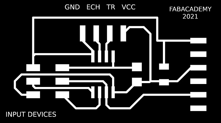
The schematic and board design were made in Eagle.
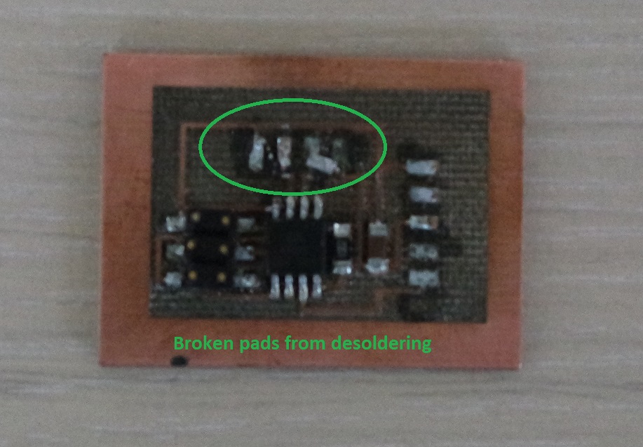
Next I soldered the components. But unfortunately I missed that step at some point and I had to desolder a few of them.
But by doing so I broke a few pads and decided to start my board all over again.
This is the damaged board after trying to unsolder it:
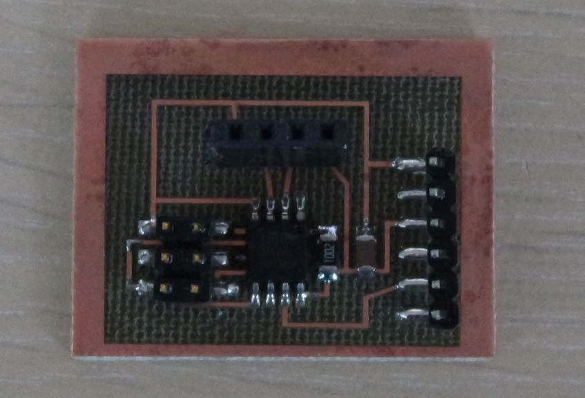
And this is my second attempt. A least I have the feeling that I'm getting better at soldering:
The microcontroller is programmed via an Arduino Uno used as an ISP.
To do so the board is connected to the Arduino by making these connections:
Make sure to connect the anode to the GND pin on the Arduino.
And I reused the code we used before for testing this sensor during our group assignment except that I added the following lines:
And also:
Everything looked fine but my Arduino serial monitor doesn't display anything.
It might either be that:
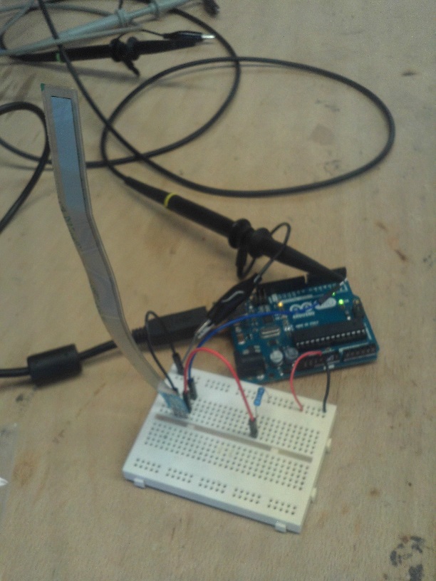
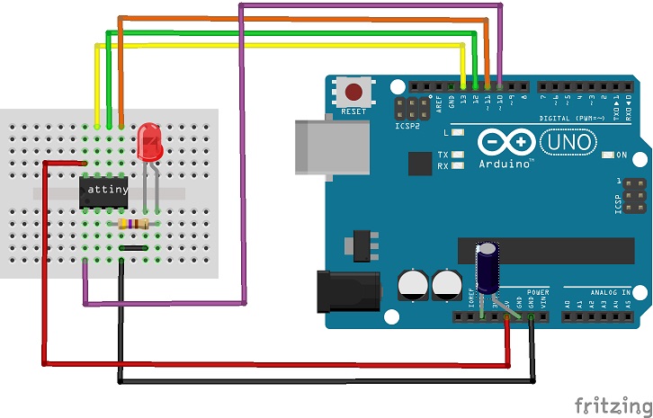
To answer that question I decided to connect a push button and a led in place of the echo and trigger of the sensor.
And then reuse the code that I previously used on week8 because by doing this the two boards are now very similar. I made all my connections on a breadboard:
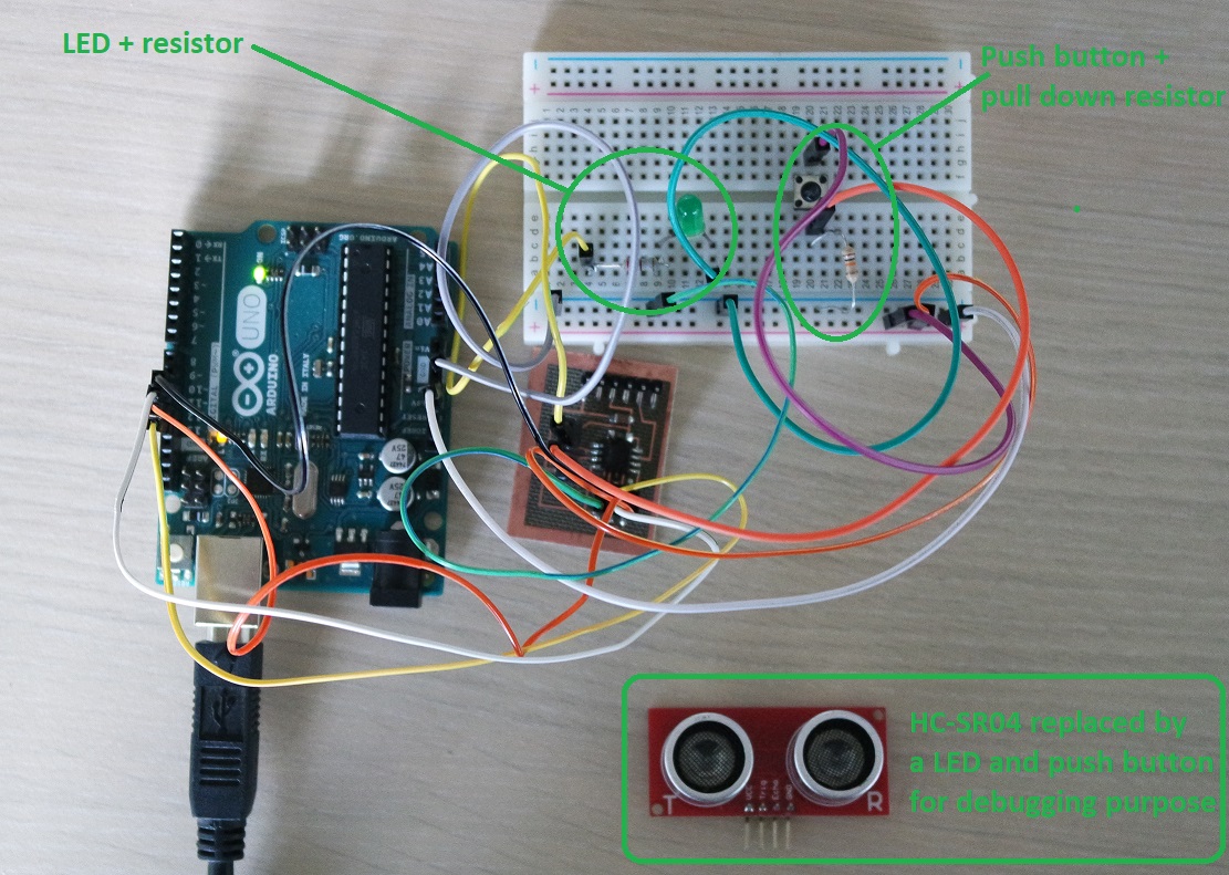
My board showed no hardware problem and the push button and LED are working as expected:
So I can conclude that it's not an hardware problem.
Are my connections correct ?
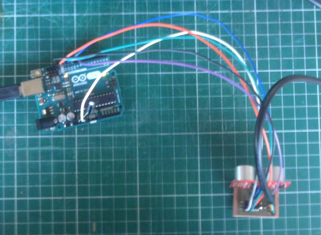
From the previous test I removed the two wires that are connected to PB3 and PB4 on my card and I reconnected the HC-SR04 sensor back.
This way I'm sure that the connections can't be wrong because of the previous test.
Is my code correct?
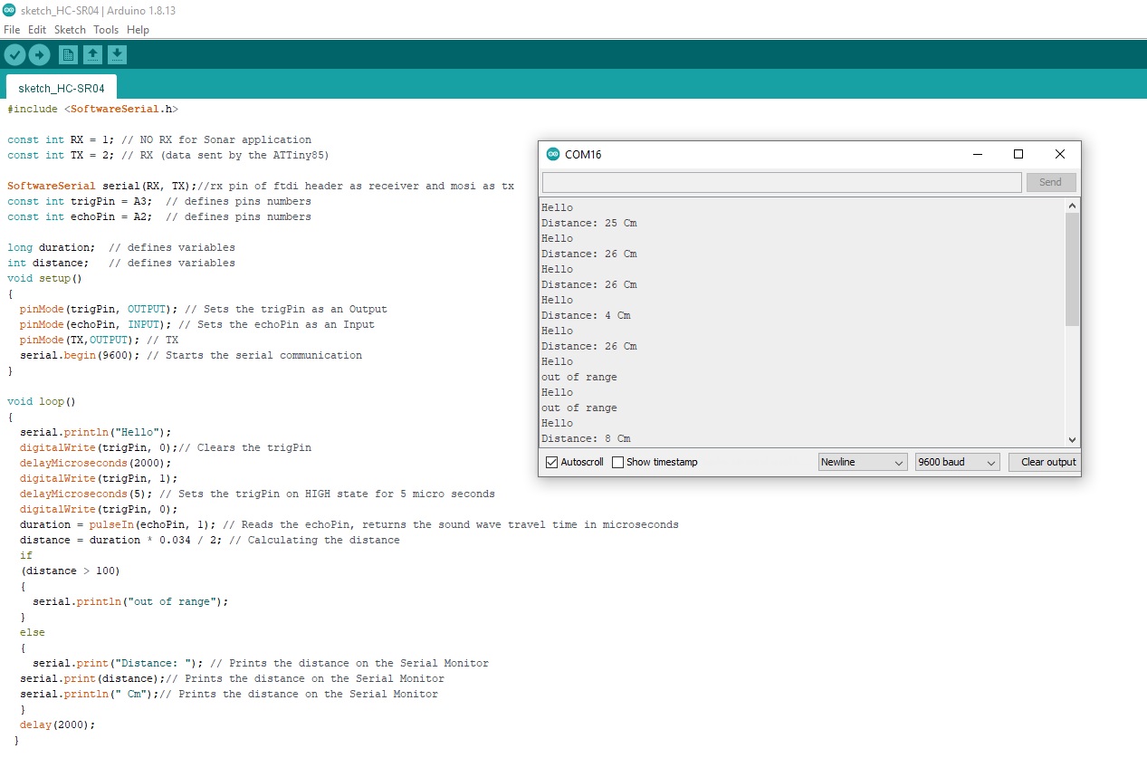
I then reworked my code:
And this time I can receive measured distance from the sensor back to the Arduino IDE serial monitor:
HCSR04.brd
And the group assignment is to probe an input device's analog levels and digital signals.
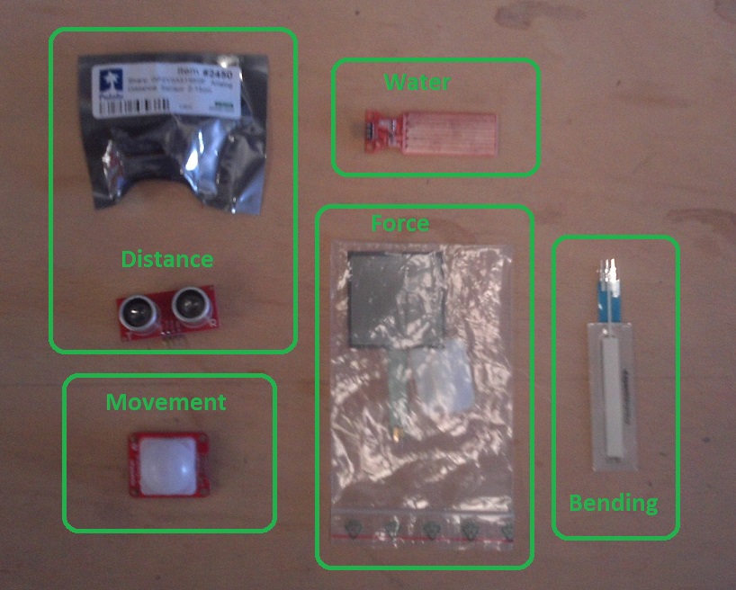
Type of sensors
We have several sensors we can play with in the lab:- temperature sensor
- movement detector
- bending sensor
- distance sensor (sonar)
- humidity sensor
- pressure sensor
- touch sensor
- color sensor
- etc.
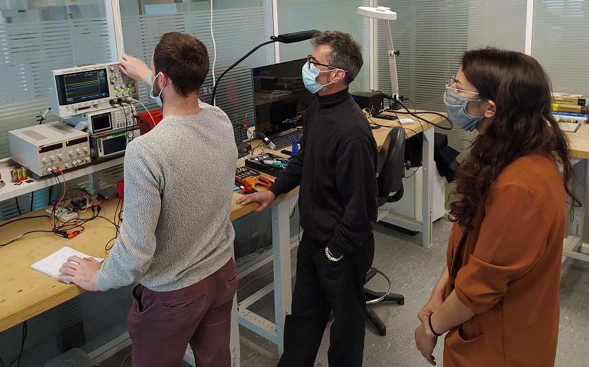
Group assignment
We connected different sensors to an Arduino board one at a time and used the oscilloscope to visualize the signals that was either emmitted or reseived.
The first sensor's signals we did look at is a ultrasonic distance sensor (sonar). It can be used to measure distances by emmiting ultrasonic and measuring the time it takes for them to come back to the sensor.
We were able to visualize both the emitting signal or "Triger" (showed in yellow) and the received signal or "Echo" (showed in green).
We even were able to visualize the emitted ultrasonic burst (showed in blue).
The next sensor's signal we looked at was for a bending sensor. The first thing we did was to measure its resistance with a multimeter.
Without bending it we could read a 10k Ohms resistance that dropped down to about 6k Ohms when bended.
So it's a resistor variable device. As only tension signals (voltage) can be displayed on a osciloscope we used a voltage divider circuit to visualize the sensor's signals variations.
Individual assignment
Arduino sensors testing
As this is completely new to me, I started by trying to connect some sensors on a Arduino board and use the Arduino IDE to monitor the signals.Distance sensor
The 1st sensor I tried is a distance sensor (sonar) connected to a Arduino board.After installing the HCSR04 library, I wrote some simple code to read out the signals and display them on the monitor.
/* Distance measure with a HC-SR04 sensor and Arduino
Connections:
- VCC to Arduino 5V
- GND to Arduino GND
- Trig to Arduino pin2
- Echo to Arduino pin3
*/

#include <HCSR04.h> // HCSR04 library by Martin Sosic

// defines pins numbers
const int trigPin = 2;
const int echoPin = 3;

// Initialize sensor that uses digital pins trigPin and echoPin
UltraSonicDistanceSensor distanceSensor(trigPin, echoPin);

void setup() {
	// Initialize serial connection to 9600 baud to print values from sensor
	Serial.begin(9600);
}

void loop() {
	// Do a measurement every 500 miliseconds and display the result in cm on serial port
	Serial.println(distanceSensor.measureDistanceCm());
	delay(500);
}
And here are the measured distance returned by the sensor:
Passive Infrared sensor
The next sensor I tested is a Passive Infrared sensor (PIR). These are used to detect motion.It has 4 pins labeled:
- A for Analog output connected to Arduino A0
- VCC for Power supply input connected to Arduino 5V
- GND for Ground supply input connected to Arduino GND
- OUT for Digital output signal connected to Arduino Pin2
Here is the Arduino sketch I used (the sketch is from this tutorial):
// Hardware configuration //

#define PIR_AOUT A0  // PIR analog output on A0
#define PIR_DOUT 2   // PIR digital output on Pin2
#define LED_PIN  13  // LED to illuminate on motion

#define PRINT_TIME 100 // Rate of serial printouts
unsigned long lastPrint = 0; // Keep track of last serial out

void setup()
{
	Serial.begin(115200);  // Serial is used to view Analog out
	// Analog and digital pins are both set as inputs:
	pinMode(PIR_AOUT, INPUT);
	pinMode(PIR_DOUT, INPUT);

	// The motion indicator LED pin is set as output and turned off
	pinMode(LED_PIN, OUTPUT);
	digitalWrite(LED_PIN, LOW);
}

void loop()
{
	// Read OUT pin and set LED to mirror output
	readDigitalValue();

	// Read Analog pin and print the value on serial port:
	printAnalogValue();
}

void readDigitalValue()
{
	// Read the PIR's digital output
	int motionStatus = digitalRead(PIR_DOUT);
	// If motion is detected, turn the LED on
	if (motionStatus == HIGH)
	{
		digitalWrite(LED_PIN, HIGH);
		//    Serial.println("Motion detected!");
	}
	else // Otherwise turn the LED off:
	{
		digitalWrite(LED_PIN, LOW);
		//    Serial.println("No motion...");
	}
}

void printAnalogValue()
{
	if ( (lastPrint + PRINT_TIME) < millis() )
	{
		lastPrint = millis();
		// Read in analog value:
		unsigned int analogPIR = analogRead(PIR_AOUT);
		// Convert 10-bit analog value to a voltage
		// (Assume high voltage is 5.0V.)
		float voltage = (float) analogPIR / 1024.0 * 5.0;
		// Print the reading from the digital pin.
		// Mutliply by 5 to maintain scale with AOUT.
		Serial.print(5 * digitalRead(PIR_DOUT));
		Serial.print(',');    // Print a comma
		Serial.print(2.5);    // Print the upper limit
		Serial.print(',');    // Print a comma
		Serial.print(1.7);    // Print the lower limit
		Serial.print(',');    // Print a comma
		Serial.print(voltage); // Print voltage
		Serial.println();
	}
}
And here is what the Arduino IDE's visual plotter shows. Orange is the analog signals that triggers if it exceed the upper and lower thresholds (Red and Green lines). The digital signal is shown in Blue:
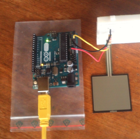
Force Sensitive Resistor (FSR)
The last sensor I tested is a Force Sensitive Resistor like this one.As the force on the sensor increases or decreases it varies the resistance. So it's very similar to the fexible bending sensor we used in the group assignment.
The more you push on the sensor, the lower the resistance will be.
Combined with a resistor to make a voltage divider we can have a variable voltage.
I used a 4.7k Ohms resistor.
Here is the Arduino sketch I used (the sketch is from this tutorial):
/*
Voltage divider circuit combining an FSR with a resistor.
- The resistor should connect from A0 to GND (modify its value in the code).
- The FSR should connect from A0 to 3.3V or 5V (modify this value in the code).
As the resistance of the FSR decreases (increase in pressure), the
voltage at A0 increase.
*/

const int FSR_PIN = A0; // A0 Pin connected to FSR/resistor divider

// Measure the voltage at 5V and resistance of your 3.3k resistor, and enter
// their value's below:
const float VCC = 4.98; // Measured voltage of Ardunio 5V line
const float R_DIV = 4700.0; // Measured resistance of voltage divider's resistor

void setup()
{
	Serial.begin(9600);
	pinMode(FSR_PIN, INPUT);
}

void loop()
{
	int fsrADC = analogRead(FSR_PIN);
	// If the FSR has no pressure, the resistance will be
	// near infinite. So the voltage should be near 0.
	if (fsrADC != 0) // If the analog reading is non-zero
	{
		// Use ADC reading to calculate voltage:
		float fsrV = fsrADC * VCC / 1023.0;
		// Use voltage and static resistor value to
		// calculate FSR resistance:
		float fsrR = R_DIV * (VCC / fsrV - 1.0);
		Serial.println("Resistance: " + String(fsrR) + " ohms");
		// Guesstimate force based on slopes in figure 3 of
		// FSR datasheet:
		float force;
		float fsrG = 1.0 / fsrR; // Calculate conductance
		// Break parabolic curve down into two linear slopes:
		if (fsrR <= 600)
			force = (fsrG - 0.00075) / 0.00000032639
		else
			force =  fsrG / 0.000000642857;
		Serial.println("Force: " + String(force) + " g");
		Serial.println();

		delay(500);
	}
	else
	{
		// No pressure detected
	}
}
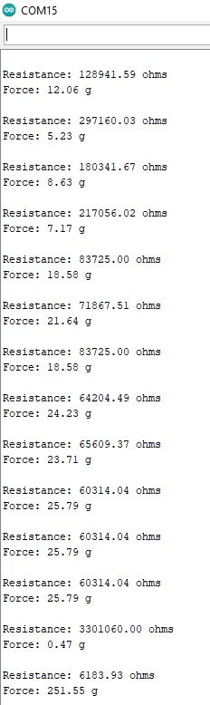
And here are different measures I got with different objects placed on top of the sensor:
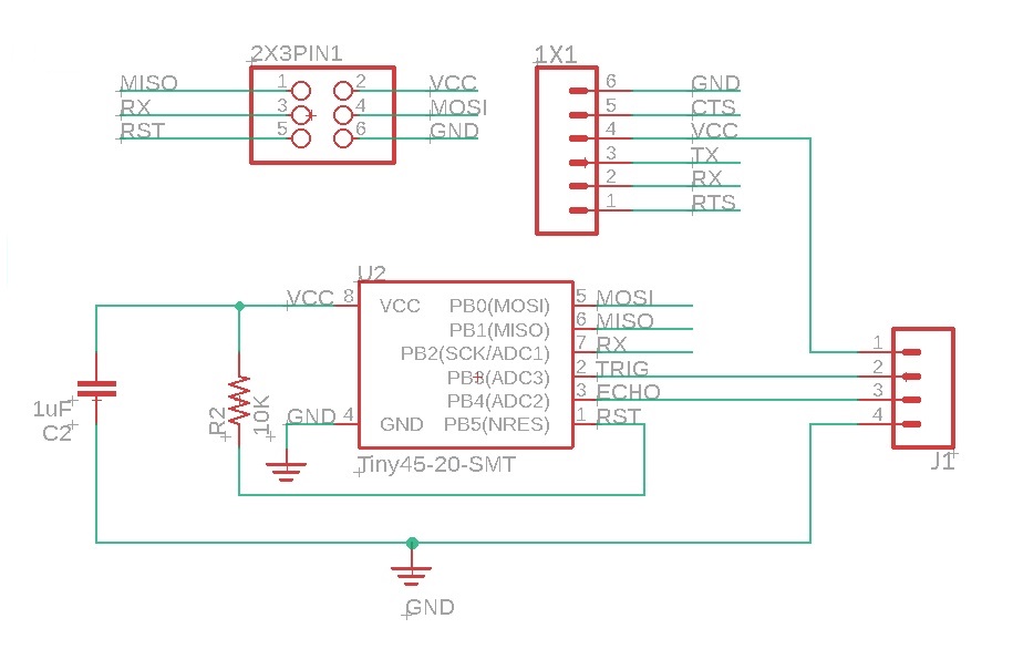
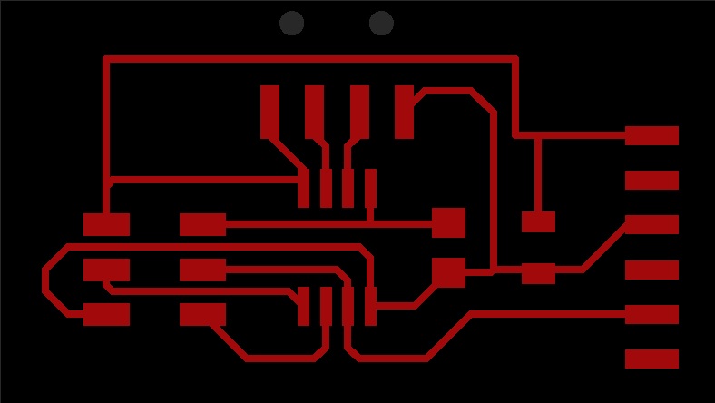
HC-SR04 board fabrication
I also tried to design and make a board with an ATtiny85 microcontroller and a HC-SR04 distance sensor.The schematic and board design were made in Eagle.
Next I soldered the components. But unfortunately I missed that step at some point and I had to desolder a few of them.
But by doing so I broke a few pads and decided to start my board all over again.
This is the damaged board after trying to unsolder it:
And this is my second attempt. A least I have the feeling that I'm getting better at soldering:
HC-SR04 board testing and programming
The next step is to test the board and program the microcontroller.The microcontroller is programmed via an Arduino Uno used as an ISP.
To do so the board is connected to the Arduino by making these connections:
- Arduino pin 13 must be connected to SCK
- Arduino pin 12 must be connected to MISO
- Arduino pin 11 must be connected to MOSI
- Arduino pin 10 must be connected to RST (RESET)
- Arduino 5V must be connected to VCC
- Arduino GND must be connected to GND (GROUND)
Make sure to connect the anode to the GND pin on the Arduino.
And I reused the code we used before for testing this sensor during our group assignment except that I added the following lines:
#include <SoftwareSerial.h>

#define serial_pin_in 2
#define serial_pin_out 1
#define max_buffer 25

SoftwareSerial Serial(serial_pin_in,serial_pin_out);
And also:
pinMode(echoPin, INPUT);
pinMode(trigPin, OUTPUT);
digitalWrite(trigPin, LOW)
Everything looked fine but my Arduino serial monitor doesn't display anything.
It might either be that:
- my board is not properly designed or soldered
- the connections between my card and the Arduino are wrong
- there is a problem in my code
To answer that question I decided to connect a push button and a led in place of the echo and trigger of the sensor.
And then reuse the code that I previously used on week8 because by doing this the two boards are now very similar. I made all my connections on a breadboard:
My board showed no hardware problem and the push button and LED are working as expected:
So I can conclude that it's not an hardware problem.
Are my connections correct ?
From the previous test I removed the two wires that are connected to PB3 and PB4 on my card and I reconnected the HC-SR04 sensor back.
This way I'm sure that the connections can't be wrong because of the previous test.
Is my code correct?
I then reworked my code:
#include <SoftwareSerial.h>

const int RX = 1; // NO RX for Sonar application
const int TX = 2; // RX (data sent by the ATTiny85)

SoftwareSerial serial(RX, TX);//rx pin of ftdi header as receiver and mosi as tx
const int trigPin = A3;  // defines pins numbers
const int echoPin = A2;  // defines pins numbers

long duration;  // defines variables
int distance;   // defines variables
void setup()
{
  pinMode(trigPin, OUTPUT); // Sets the trigPin as an Output
  pinMode(echoPin, INPUT); // Sets the echoPin as an Input
  pinMode(TX,OUTPUT); // TX
  serial.begin(9600); // Starts the serial communication
}

void loop()
{
  serial.println("Hello");
  digitalWrite(trigPin, 0);// Clears the trigPin
  delayMicroseconds(2000);
  digitalWrite(trigPin, 1);
  delayMicroseconds(5); // Sets the trigPin on HIGH state for 5 micro seconds
  digitalWrite(trigPin, 0);
  duration = pulseIn(echoPin, 1); // Reads the echoPin, returns the sound wave travel time in microseconds
  distance = duration * 0.034 / 2; // Calculating the distance
  if
  (distance > 100)
  {
    serial.println("out of range");
  }
  else
  {
    serial.print("Distance: "); // Prints the distance on the Serial Monitor
  serial.print(distance);// Prints the distance on the Serial Monitor
  serial.println(" Cm");// Prints the distance on the Serial Monitor
  }
  delay(2000);
 }
w10_HC-SR04.inoAnd this time I can receive measured distance from the sensor back to the Arduino IDE serial monitor:
Files for this week
HCSR04.schHCSR04.brd