Electronics design
The assignement for this week is to redraw an echo hello-world board, add a button and LED, check the design rules, make it, and test it.
So I started by reading its datasheet.
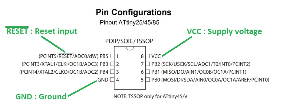
I also paid attention to the pins configuration:
For the design of the board I will use Eagle because this is the software our instructor can teach us.
When I will be familiar with it I might swap to Kicad because it's free and open-source.
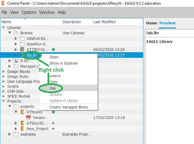
After restarting Eagle, the new libraries are then available for use:

To make this board we need:
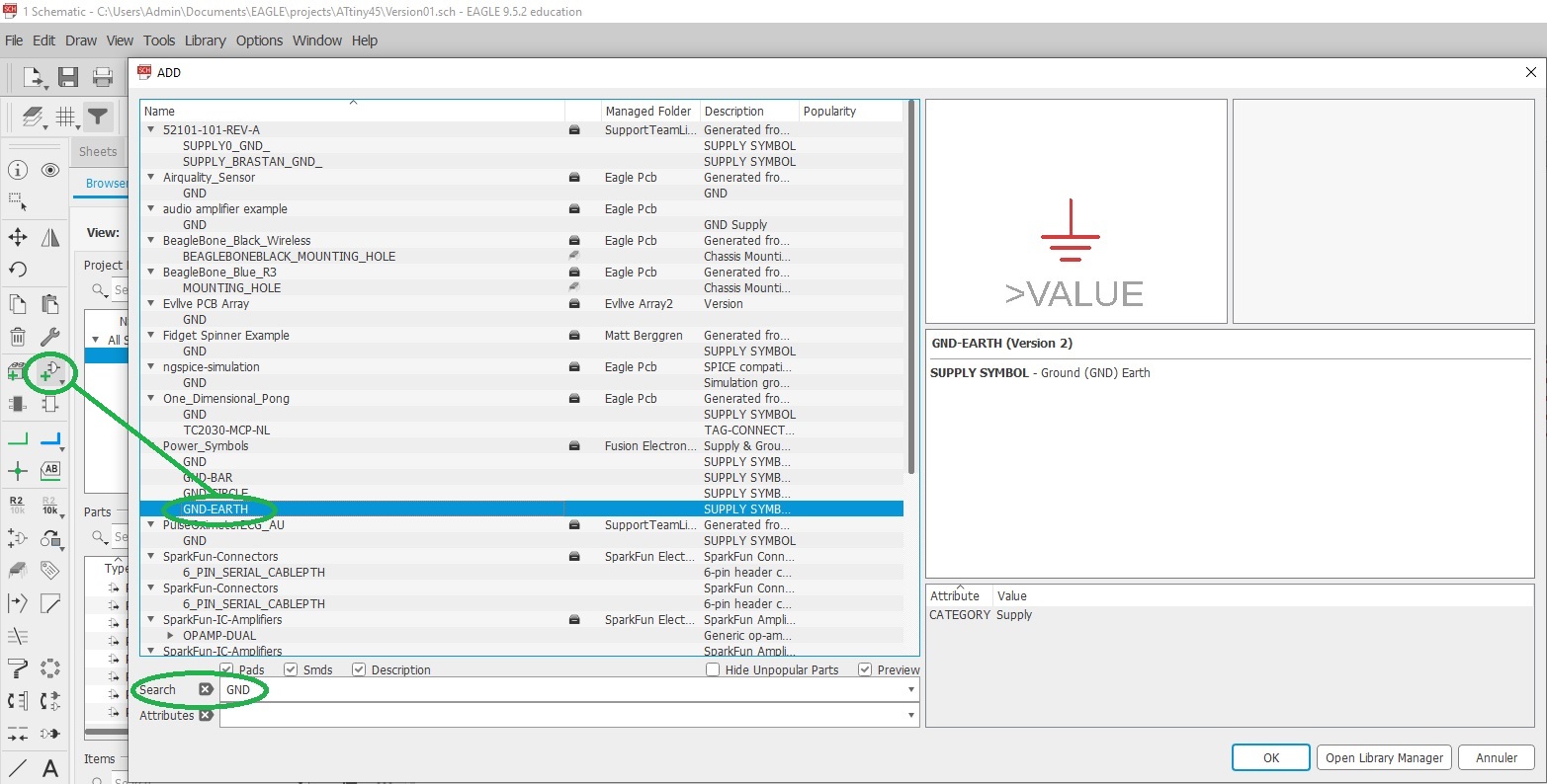
To add a part simply click on the "Add part" icon, optionally use the "Search" function, and click on the desired part:
Name and value of our components can be changed by right-clicking on them:
Here is my schematic after adding, renaming, and giving a value to all parts except for R3 whose value still need to be calculated:
R3 is a current limiting resistor intended to protect our red led from "burning" it by applying to much current thru it. It's value needs to be calculated by following the Ohm's law
Standard red leds are rated at 1.7V and 20mA to light up properly. As we are providing 5V we have to drop it down and can calculate R3 value
The closest standard value is 180 Ohm so I'll use that.
R4 is a high value resistor (10K) that acts as a "pull-down" resisor. Its role is to ensure a clear state reading when the swith is open and avoid making a short-circuit when it's closed.
Parts need to placed and then connected following the board image provided.
These connections are made by clicking on the "Net" icon and by connecting together our components. They can also be given a name just like components:
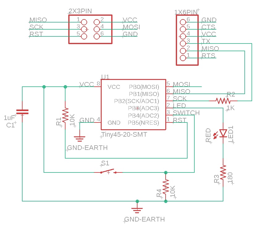
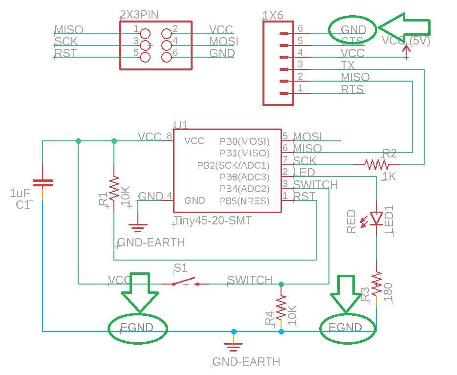
Here is my final Eagle schematic:
It's now time to organize our board by moving and rotating our components and try to place them in a convenient way:
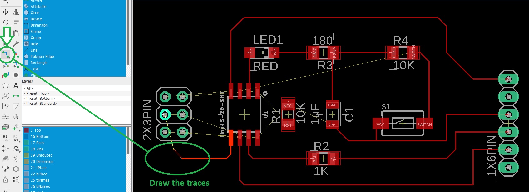
And to add the traces. Traces that are still not connected are represented as thin yellow lines while connected traces are shown red:
I realised that I used thru-holes connectors instead of surface mounted ones so I changed them.
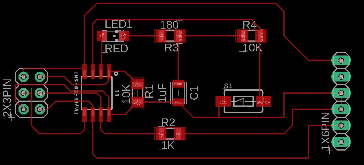
I then tried to optimize the size of the board by moving things closer to each other and that's my final result:
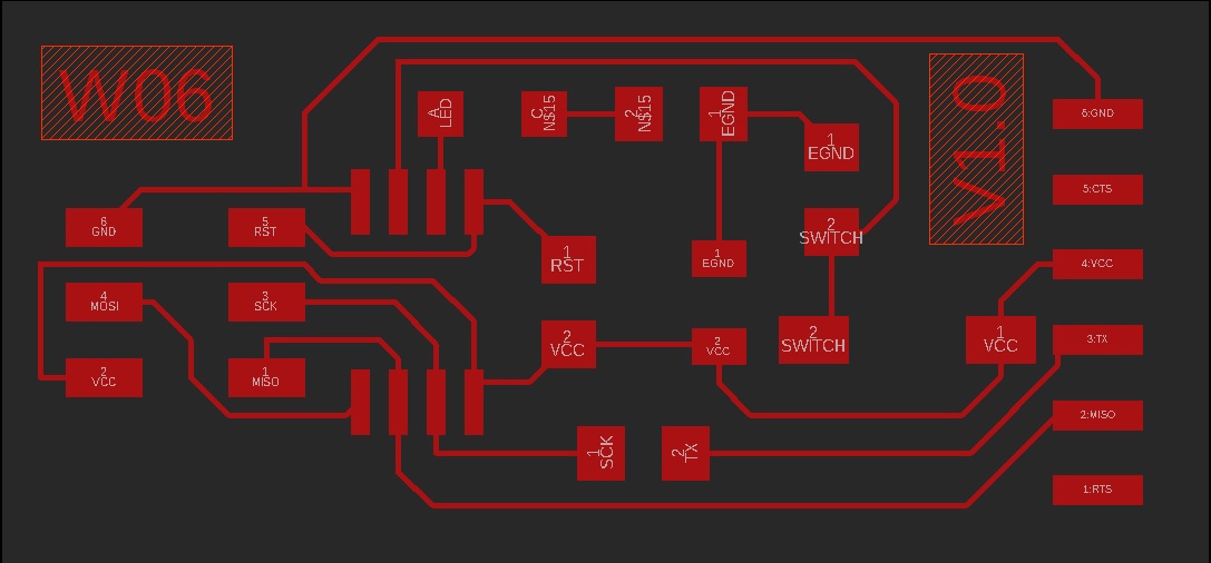
The outline of the board is drawn on the "Dimension" layer:
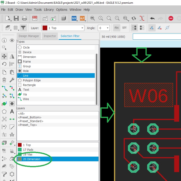
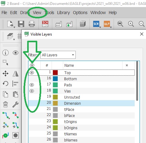
Eagle can export a black and white png image but before we need to hide unneeded layers and only keep the ones we want to engrave:
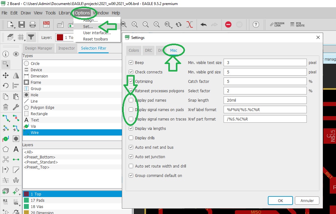
And we also need to hide names on pads, etc.:
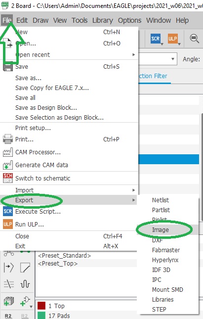
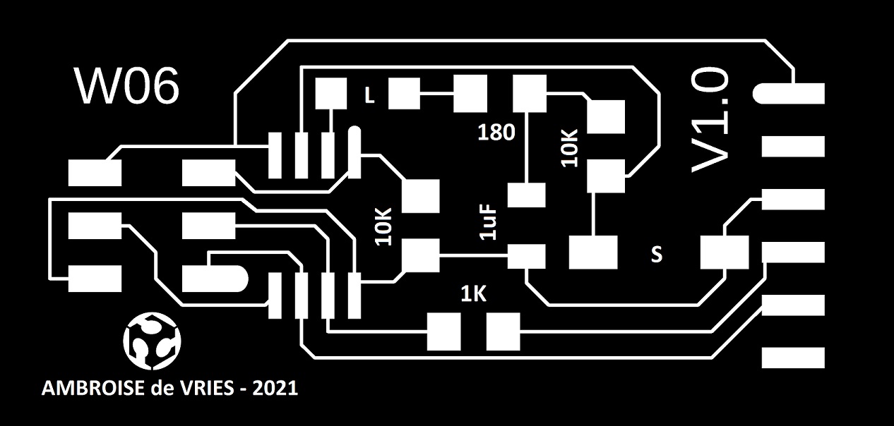
Then export your work as a monochrome .png image by clicking on "File / Export / Image":
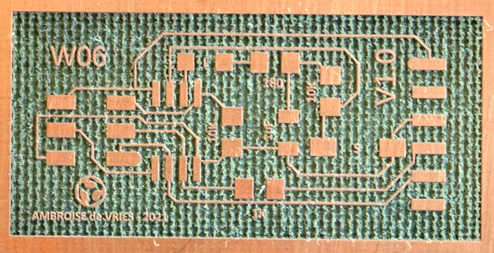
I engraved my board on a Trotec Speedy 100 Flexx with the fiber laser by alternating horizontal and vertical passes and checked it with the multimeter:
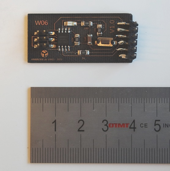
Once soldered, I checked again with a multimeter to make sure everything is fine. Here is my final board:
Our instructor Jonah sent us a simple C program along with its .hex file that will blink the led every 5 seconds.
After connecting the FABtinyISP to the board we can flash it with the .hex file provided by typing
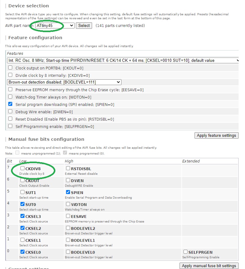
The website gives us the following code for our fuses:
If everything went well, the led should blink every 5 seconds. But unfortunately mine wasn't so I probably made a mistake somewhere...
I checked again all my connections with a multimeter to make sure that things that must be connected are connected and that things that shouldn't are not.
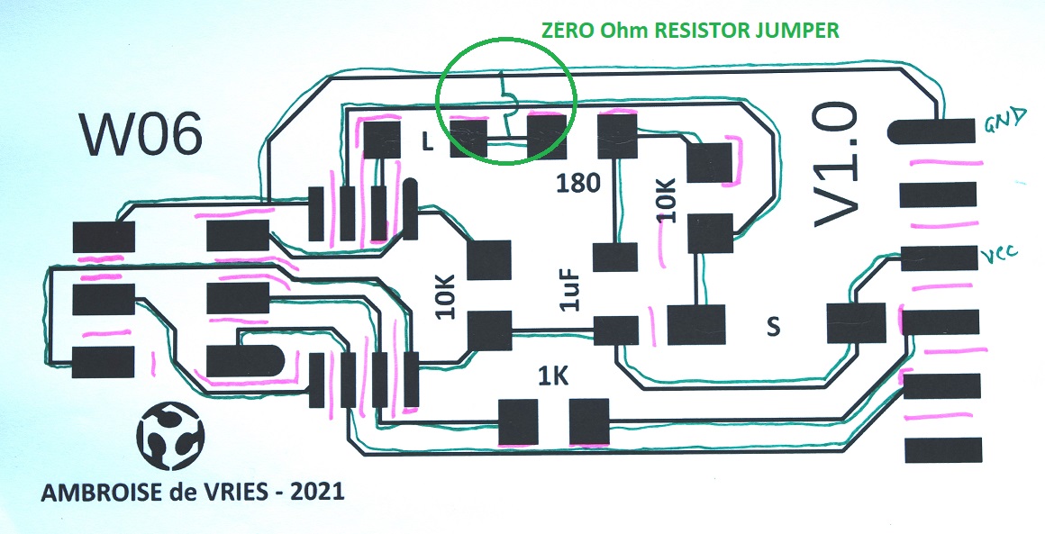
To make sure not to forget any critical point on the board, I printed it on a A4 sheet of paper and marked down every single tests I made: in green are things that are connected and in red things that are not.
This test showed that the problem is not a default in connections.
So I looked closer at my Eagle schematic and noticed that I used two different names for "ground": GND and EGND. Eagle doesn't know they are the same things and didn't connect them.
Which means that my led and capacitor aren't connected to ground.
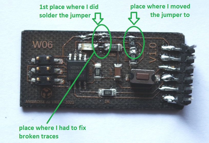
An easy way to fix that is to use a zero Ohm resistor jumper to connect back the led to the ground wire.
I had hard time at soldering it because my traces are very thin and I broke one. I realize that in the future I will have to make my traces bigger (0.4mm).
When I tested my board again it still didn't work. Then Jonah recommended me to move the zero resistor to another place.
Unsoldering it once again broke one of my traces and I had to rebuild a connection.
But finally all my problems were solved and the board is now working as expected.
But I understand how to do it and will do it soon.
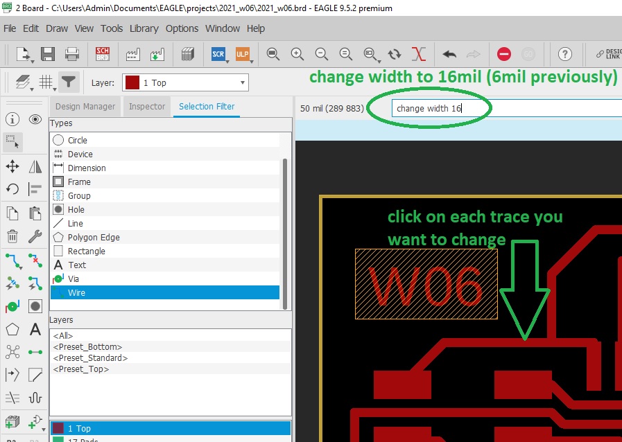
First mistake was to draw my traces to thin. It caused problems when I needed to solder my jumper to them. I will use 0.4mm traces for my future boards.
To modify the traces width you can type "change width" followed by a new value (16mil in my case) and then click on each trace you need to modify:
Second mistake was to name ground in two different ways in my Eagle schematic which leaded to components not being connected to ground. I will make sure in the future to use only one symbol for GND and VCC.
Debugging my board was very instructive and teached me a lot!
2021_w06.sch
Board choice
The only available chipsets we have in stock are the ATtiny45 and the ATtiny85. I choosed to make the ATtiny45 based on the board image provided.
So I started by reading its datasheet.
I also paid attention to the pins configuration:
Software choice
To ease our board design we use a dedicated PCB design software. There are several ones including Eagle and Kicad.For the design of the board I will use Eagle because this is the software our instructor can teach us.
When I will be familiar with it I might swap to Kicad because it's free and open-source.
Libraries
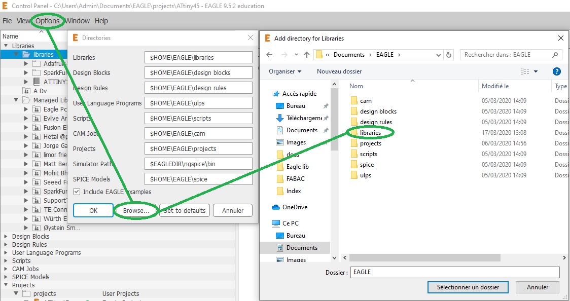
Extra Eagle libraries were added by copying the downloaded .lbr files in Eagle's "libraries" folder:After restarting Eagle, the new libraries are then available for use:
Designing the board
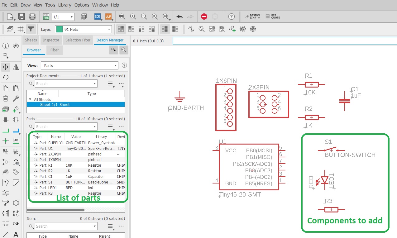
The first thing to do is to identify all the needed components based on the board image:To make this board we need:
- (1x) ATtiny45 chipset (IC1)
- (1x) 2x3 Pin Header (J1)
- (1x) 1x6 Pin Header (J2)
- (1x) 10k resistor (R1)
- (1x) 1k resistor (R2)
- (1x) 1uF capacitor (C1)
- (1x) button switch
- (1x) LED
- (1x) current-limiting resistor (150 Ohms)
Schematic design
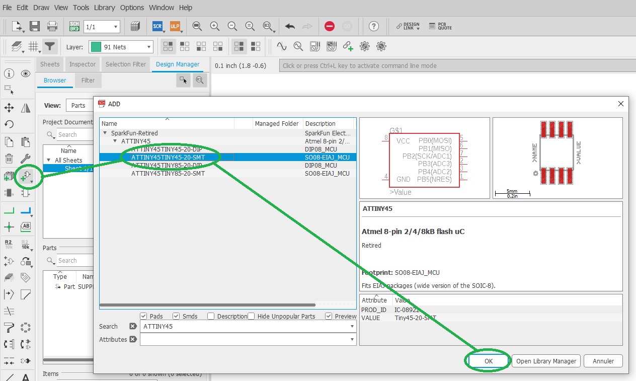
We first need to draw a schematic of the board by adding all needed parts and then connect them.To add a part simply click on the "Add part" icon, optionally use the "Search" function, and click on the desired part:
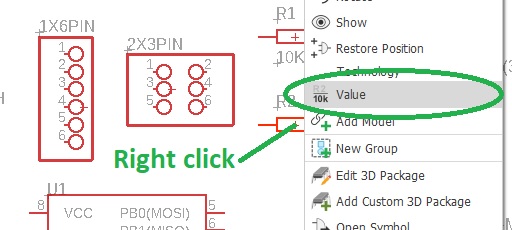
Name and value of our components can be changed by right-clicking on them:
Here is my schematic after adding, renaming, and giving a value to all parts except for R3 whose value still need to be calculated:
R3 is a current limiting resistor intended to protect our red led from "burning" it by applying to much current thru it. It's value needs to be calculated by following the Ohm's law
V=R*I.Standard red leds are rated at 1.7V and 20mA to light up properly. As we are providing 5V we have to drop it down and can calculate R3 value
R3 = (5V - 1.7V) / 0.02A = 165 Ohm.The closest standard value is 180 Ohm so I'll use that.
R4 is a high value resistor (10K) that acts as a "pull-down" resisor. Its role is to ensure a clear state reading when the swith is open and avoid making a short-circuit when it's closed.
Parts need to placed and then connected following the board image provided.
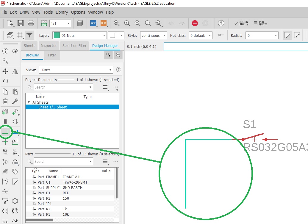
These connections are made by clicking on the "Net" icon and by connecting together our components. They can also be given a name just like components:
Here is my final Eagle schematic:
Board design
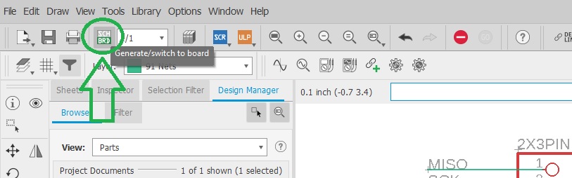
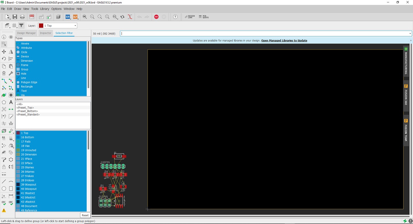
A default board design can be generated from the schematic design by simply clicking on the SCH/BRD icon:It's now time to organize our board by moving and rotating our components and try to place them in a convenient way:
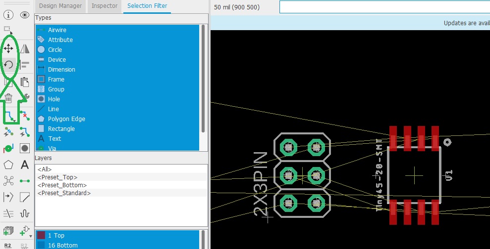
And to add the traces. Traces that are still not connected are represented as thin yellow lines while connected traces are shown red:
I realised that I used thru-holes connectors instead of surface mounted ones so I changed them.
I then tried to optimize the size of the board by moving things closer to each other and that's my final result:
The outline of the board is drawn on the "Dimension" layer:
Exporting and laser engraving
The laser engraver needs a black and white image of the traces where black will be engraved.Eagle can export a black and white png image but before we need to hide unneeded layers and only keep the ones we want to engrave:
And we also need to hide names on pads, etc.:
Then export your work as a monochrome .png image by clicking on "File / Export / Image":
I engraved my board on a Trotec Speedy 100 Flexx with the fiber laser by alternating horizontal and vertical passes and checked it with the multimeter:
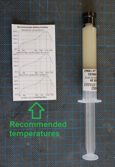
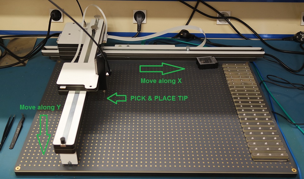
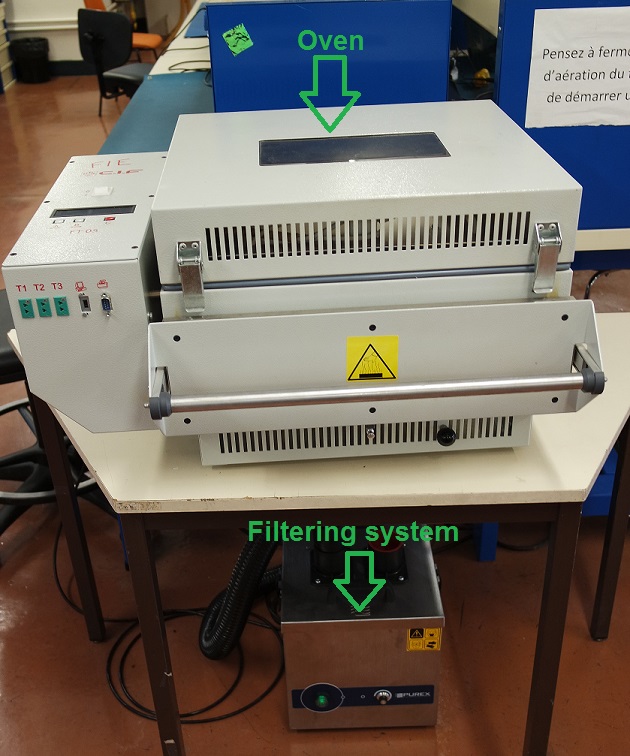
Soldering
For the soldering step I used paste solder, a pick-and-place device and a oven to "cook" the board. Except for the 1x6 pin header that was soldered by hand afterward:Once soldered, I checked again with a multimeter to make sure everything is fine. Here is my final board:
Board testing
For testing the board I programmed it with the FABtinyISP that we made on week 4.Our instructor Jonah sent us a simple C program along with its .hex file that will blink the led every 5 seconds.
After connecting the FABtinyISP to the board we can flash it with the .hex file provided by typing
avrdude -c usbtiny -p t45 -P usb:002:013 -U flash:w:Blink_ATtiny45.hex.
Then we need to set the fuses. To know which command to use used this website and set our fuses the way we need them.The website gives us the following code for our fuses:
-U lfuse:w:0xe2:m -U hfuse:w:0xdf:m -U efuse:w:0xff:m.If everything went well, the led should blink every 5 seconds. But unfortunately mine wasn't so I probably made a mistake somewhere...
Board debugging
Time to investigate my schematic, board, and connections in order to find what the problem is.I checked again all my connections with a multimeter to make sure that things that must be connected are connected and that things that shouldn't are not.
To make sure not to forget any critical point on the board, I printed it on a A4 sheet of paper and marked down every single tests I made: in green are things that are connected and in red things that are not.
This test showed that the problem is not a default in connections.
So I looked closer at my Eagle schematic and noticed that I used two different names for "ground": GND and EGND. Eagle doesn't know they are the same things and didn't connect them.
Which means that my led and capacitor aren't connected to ground.
An easy way to fix that is to use a zero Ohm resistor jumper to connect back the led to the ground wire.
I had hard time at soldering it because my traces are very thin and I broke one. I realize that in the future I will have to make my traces bigger (0.4mm).
When I tested my board again it still didn't work. Then Jonah recommended me to move the zero resistor to another place.
Unsoldering it once again broke one of my traces and I had to rebuild a connection.
But finally all my problems were solved and the board is now working as expected.
Board programming
The debugging step above took me quiet a bit of time and unfortunately I didn't have enough time left to program my board with Neil's "Echo Hello-world" program...But I understand how to do it and will do it soon.
Conclusion
This week I learned a lot of things and especially from my mistakes.First mistake was to draw my traces to thin. It caused problems when I needed to solder my jumper to them. I will use 0.4mm traces for my future boards.
To modify the traces width you can type "change width" followed by a new value (16mil in my case) and then click on each trace you need to modify:
Second mistake was to name ground in two different ways in my Eagle schematic which leaded to components not being connected to ground. I will make sure in the future to use only one symbol for GND and VCC.
Debugging my board was very instructive and teached me a lot!
Files for this week
2021_w06.brd2021_w06.sch