Week 16
Interface and Application Programming
MOOD OF THE WEEK

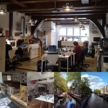
This week we were in Amsterdam to visit our friends from Waag ! We got to visit their fablab, and work with them a little. It was fun to see how they were organised over there !
Lucky me, this week was a success and I have time to do some catching up on my past documentation.
I did some of the bare minimum but I really wanted to have time to work on the rest I had to do, since I'm a little left behind.
Interface and Application Programming
This week's assignments :
- Group assignment
- compare as many tool options as possible
- Han Solo assignments :
- write an application that interfaces with an input &/or output device that you made
Group Assignment
Here is the link to our documentation for the group assignment : http://fabacademy.org/2019/labs/sorbonne/group_work/interface_application/
Han Solo Assignment
Step 0 : installing and discovering Processing
First, go to the downloading webpage of Processing to find the link to install the software : http://processing.org/download. Follow the procedure depending on wether you are on Mac, Linux or Windows.
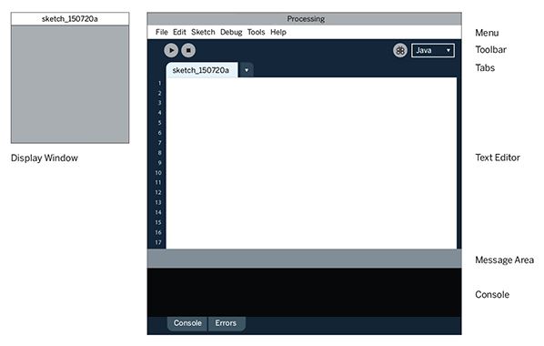
Here is the Processing development environment :
Step 1 : connecting Arduino/Hello Board to Processing
First things first, I have to understand how to connect my board to Processing. In order to do this, I’m following this good tutorial on Sparkfun : https://learn.sparkfun.com/tutorials/connecting-arduino-to-processing/all
A/ From Arduino to Processing
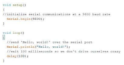
Here, I’m just gonna try showing the “Hello World” sent from my Arduino in the Processing monitor.
Here is the code I put on the Arduino IDE
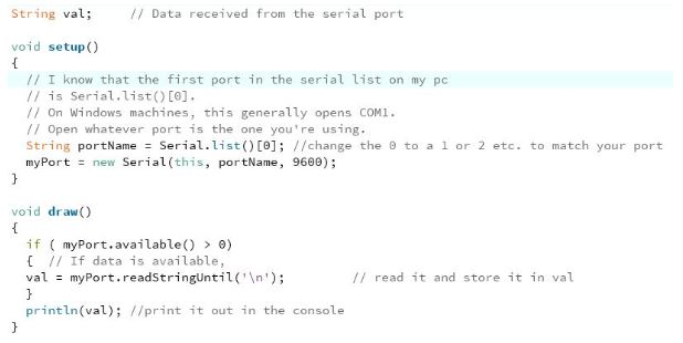
And in Processing
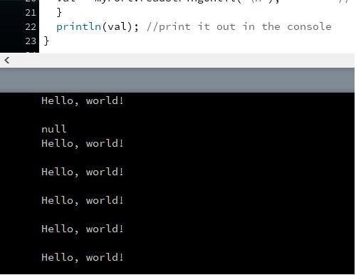
It works ! Here is the result in Processing :
Now that I know how to do it with Arduino, let’s try to do it with the board.
B/ From Hello Board to Processing
Just make the “Hello World” appear on the Processing monitor
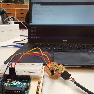
As usual, first be sure to turn your Arduino into an ISP with the ArduinoISP exemple.
- Pin13(arduino) to SCK
- Pin12 (arduino) to MISO
- Pin11(arduino) to MOSI
- Pin 10(arduino) to RESET
- 5V to VCC
- Gnd to Gnd
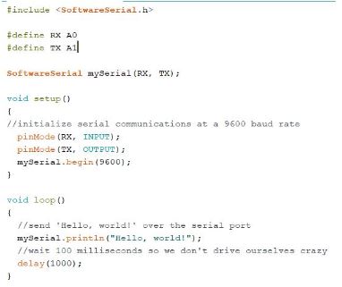
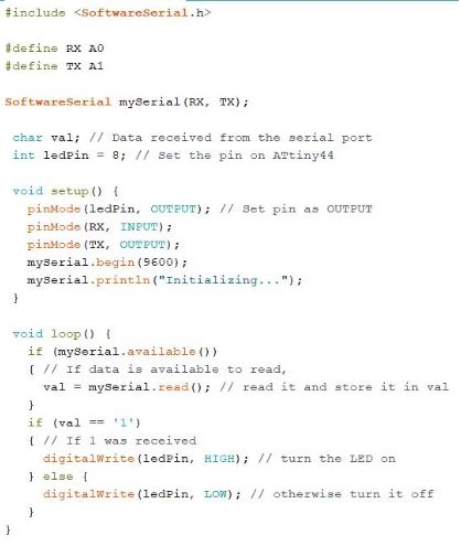
I have to change my Arduino code a bit, because I need to use the SoftwareSerial library. Here is what it looks like :
When you do this exercise with a PCB done by yourslef and Processing, you must be sure you call the right port in your code.
This call corresponds to this line of code :
String portName = Serial.list()[0];
If you don't select the right one, you should see a "null" result appear on your monitor.
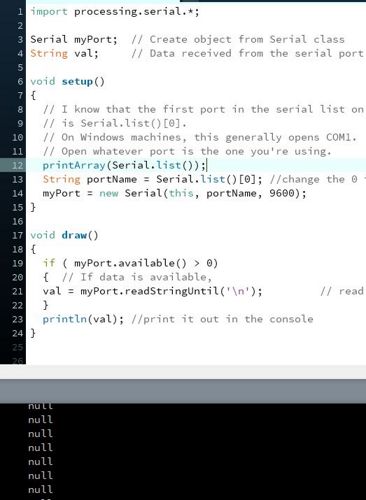
In order to know which port your board is connected to, you can just add this line of code and then delete it to know which number (0, 1 or so) you have to put in the line explained just before.
Here is the line you should put :
printArray(Serial.list());
Here is what you should see on your Processing monitor.
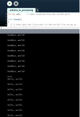
All this said, everything works fine, I can go further ! And you can see on the picture below that my code works :)
Adding a blinking led to the process and changing the message in Processing monitor
I modified the code a lil’ bit, so the LED from the board blinks. When it’s HIGH, it sends “Hello World”, when it’s LOW, it sends “Goodbye World”.
Yeah, it also works !
Step 2 : From Processing to Arduino/Hello Board
A/ From Processing to Arduino
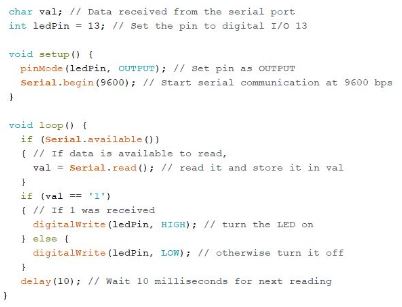
This time, I want to do something in Processing (here, just clicking on a grey square) and it lights up a led on my breadboard.
Here is my code on Arduino :
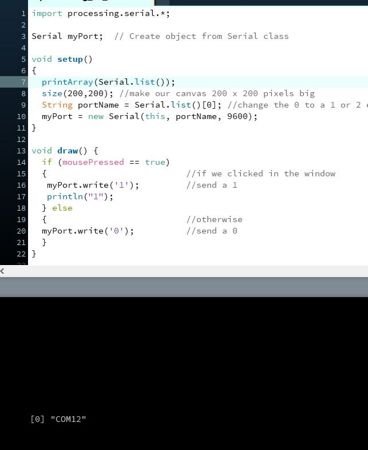
Here is my Processing code :
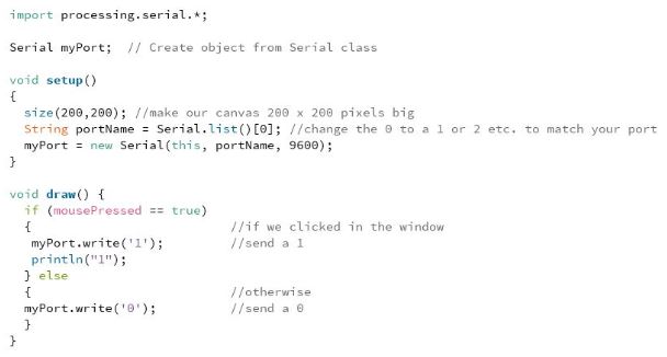
and look, it works ! :)
B/ From Processing to Hello Board
Let’s try to make this code work with the Hello Board then and see if it works as well as the first exemple.
Important changes :
- The LED is on PB2, so I have to indicate “8” as an output on my code.
- Erase the “delay” in the loop. Otherwise the program will spend more time delaying than executing the action of lighting up the LED.
Here is the code I upload to the Hello Board :
UPDATE : Previously, in the "Hello Board's World"
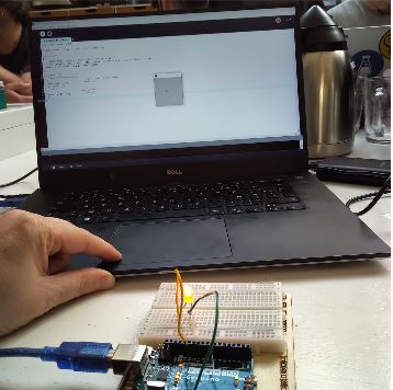
As I'm a clever person I forgot my computer and boards at home wefore going to Amsterdam ^^' Early train is not good for my brain ^^' (that could be a t-shirt). I had to borrow a computer and Adel told me to borrow an Hello Board to do my assignment. I did another one in Paris afterwards, I talk about it in week 14. I won't detail again the process of making it since it's in my electronic design week.
I thought it would be interesting to take a look at Amsterdam's CNC machine, since it's different than ours. All the preparation is not the same, so I read the instructions in Anne's documentation and Rutgers's documentation. Their group assignment of week 5 explains how the MDX20 desktop cnc milling machine they have works. It's not that different from our Roland.
A word about the mdx20 cnc milling machine
Here's what the machine looks like :
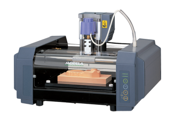
I was interested to find out a major difference with our Roland SRM20. Although this machine is mostly used to mill circuits, but it could also do 3D scanning ! It uses a thin needle to gently touch the object and calculates from this a 2 and a half dimensional model. Though slow at processing, it can create a high detailed model.
I found this really interesting video explaining how the 3D scanning works with this CNC:
UPDATE TO THE UPDATE : Got it working again after all !
What a journey my friends... It's been a few months since the last time I updated this site. What was supposed to be simple appeared to be not that simple to achieve after all. I had to do exactly the same exercice I did before, but with a board of mine. Easy you say ? That's without counting in the countless bumps I found on the road ^^'
CHAPTER 1 : The first tries
First I had to find material to make my board work. Indeed, without any access to the Sorbonne Fablab and no money in the bank account to buy it, the task was a bit more difficult.
I could find a moment to catch up with Madjid that lended me his FTDI cable so I could do my exercice again. I chose to use my original Hello Board. Got home and tried for a while, but my board did not seem to be working. Many reasons possible, the one : I got corrosion on it, which led to circuit problems.
What is corrosion ? It is the process of oxidation that happens when oxygen bonds with metal, producing rust and causing the metal to flake off and lose its valuable chemical properties. Since printed circuit boards are largely made of metal and are exposed to oxygen, they must corrode eventually.
It is possible to clean it but you should disassemble your PCB in order to do it, and it wasn't possible for me since my board is in CMS. Too many risks in damaging even more the components.
I tried with the new Hello Board board I made after coming back from Amsterdam and that I used to make my bluetooth exercice. Since this previous has been validated without issues a fex months ago, I was sure I could use this board.
Problem is : it appeared I couldn't get any serial communication with it... This was really a big bump in the moral and motivation. Especially because I had no Roland to make a new board...
But thanks to my friend Victor told me I could do a new circuit board with the laser cutter. Some silver lining appears, a completely new technique so I'm not sure I will have time to complete everything but at least I'm gonna try.
CHAPTER 2 : making a board with the laser cutter
Since I lacked of time, I couldn't get through the entire process but here are my first tries. I followed this nice documentation from the "Carrefour Numérique" (a Fablab in Paris) : http://carrefour-numerique.cite-sciences.fr/fablab/wiki/doku.php?id=projets:pcb_laser_na2s2o8
What you have to do is take your copper plate and paint it with regular paint bomb. And you must be careful not to make a too thick layer of paint, otherwise it will be difficult ot engrave (I experienced it ^^). And preferably use black paint. I tried with pink one and it did not come as well.
One important thing I discovered also, was that I had to change the sizes of all my roads in order to make them appear properly. Otherwise they will be wipped off my board with the different chemicals and not usable. I engraved it twice on the black copper plate, but I wasn't happy with the sizes of the roads that seemed too small.
It was hard for me to find the proper dimension, I had to make several tries of engraving to approach the good result. In Eagle, a size 32 seems not too bad.
To prepare your circuit file from Eagle, you must save your file as an image and at a 500 dpi resolution. I did some tests and the proper parameters to engrave my board were : speed : 60 and power : 25.
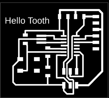
The letters of my board I made on Eagle didn't appear on LaserCAD, so I suppressed them and wrote the "Hello Tooth" directly in the laser software.
Here is a video of the circuit being engraved :
Here is the result once engraved :
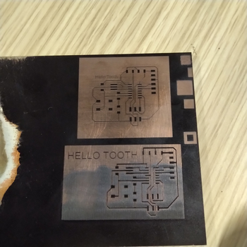
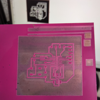
Like you can see on the picture, it didn't came out well. I decided to do one last try, with another copper plate and pink paint this time. It was nice and it did not work as well as I expected, I think black is best for this kind of engraving.
CHAPTER 3 : hello board bis rising up from the dead
Hum, time is against me again... what can I do ? I don't have a proper new circuit, I have a few days left to do the job, and I work like 60 hours a week since septembre... Let's try again to use my previous hello board (the one from the bluetooth assignment). As we say in french : "you never know, on a misunderstanding it could work".
I called for help from my friend Victor again, and we tried to figure out what went wrong with this board. Maybe with two brain it can work ! And it appears that... it was a double issue : FTDI cable was not working well and a driver problem to read the serial communication.
To solve those problem, I adopted two techniques in paralell :
- Change the cable of the FTDI adapter so I can be sure I communicate properly with it.
- Use my computer to implement the arduino code and use my friend's macintosh to run the processing program and read the serial, since the driver was working fine on his laptop.
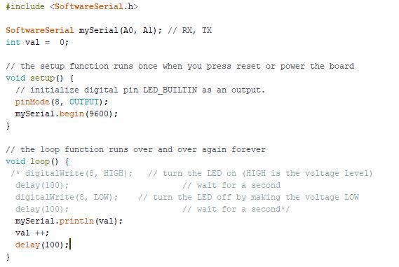
Let's do a first simple incrementation test code, to see if I can read the serial like this now.
HALLELUIA IT WORKS
Now, I just have to upload the code I already did for this exercise... and it works again !! :D
As I want to be sure I won't have to do anything again for the Fabacademy and especially for this exercise, I did a small other exercise. Just changed the code a bit to turn on and off the led when I click. The processing code stays the same, I have to change in Arduino. Here is the code :
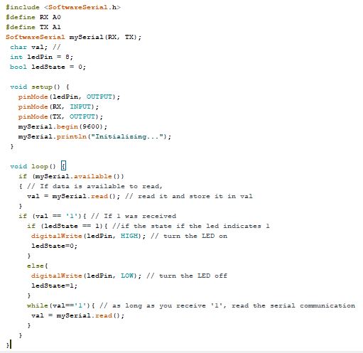
And here is the video of the code working :
Wanna try by yourself ?
Here are all the links to my files, feel free to download them :
| Name of the documents | Link to download |
|---|---|
| Arduino files | Arduino to Processing |
| Arduino files | Processing to Arduino |
| Arduino files | Arduino to Processing bis, second exercise |
| Processing files | Arduino to Processing |
| Processing files | Processing to Arduino |
| Eagle files (you can use them for both the CNC and the laser cutter. Just put size of the road to 32 if you use them for the laser cutter) | Hello Board bis |