Week 5
Making Brian the PCB
MOOD OF THE WEEK

Hey ! This week was quite an improvement, I succeeded in doing my solo assignment, documenting on the group assignment AND moving a bit forward on my final project. Yeah !
I realise as the time goes by, that we don't have that much time to do the final project and mine is quite ambitious. I have to find a bit more time to move on with it, if I want it to go somewhere at some point. But I'm on the right track ! :)
Electronic mon amour
This week's assignments :
- Group assignment
- characterize the design rules for your PCB production process
- Han Solo assignments :
- make an in-circuit programmer by milling the PCB
- program it
- then optionally try other PCB processes
Group Assignment
Here is the link to our documentation for the group assignment : http://fabacademy.org/2019/labs/sorbonne/group_work/electronics-prod/
Han Solo Assignment
Make an in-circuit programmer by milling the PCB
This week, we do not have to be creative, but we have to be precise. Electronic production, here we come !
I’m kinda stressed coz I didn’t do that well on the pre-week. But I’ll try my best to get whatever I can from it :) I think it’s gonna be more about doing research and understanding this week than really making something different. But once I’ll get everything I’ll win some time for after :)
So, as I said, electronic production. We have to do a tutorial from one of the student’s listed from previous years. I’ll do the simpliest one, so I can take some time to understand really how everything works.
So I’ve chosen to make Brian : http://fab.cba.mit.edu/classes/863.16/doc/projects/ftsmin/index.html
Step 1 : create the gcode (rml file)
To trace and cut Brian the PCB, we have to create an rml file.
RML stands forRedline Markup Language File
To do this, I’ll use the online software http://mods.cba.mit.edu/. It allows you, with the correct settings, to create your rml file that can be directly uploaded to your milling machine.
How to use mods ?
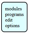
First, open mods in your web browser. You’ll have to right click and you’ll open a window. Select programs :
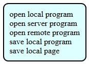
> Open server program
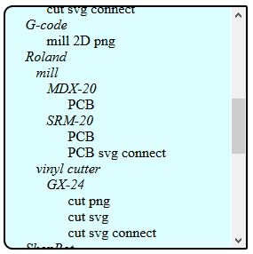
> We use a Roland Mill SRM-20. Select PCB.
> It will open a page with a bunch of modules all connected to one another. You won’t need everything, I’ll show you and explain the important ones for this particular PCB.
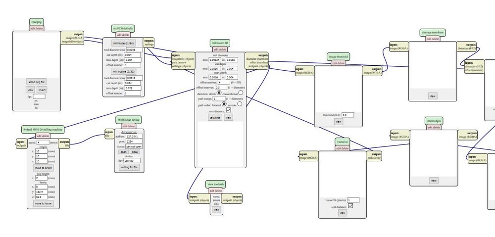
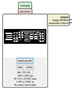
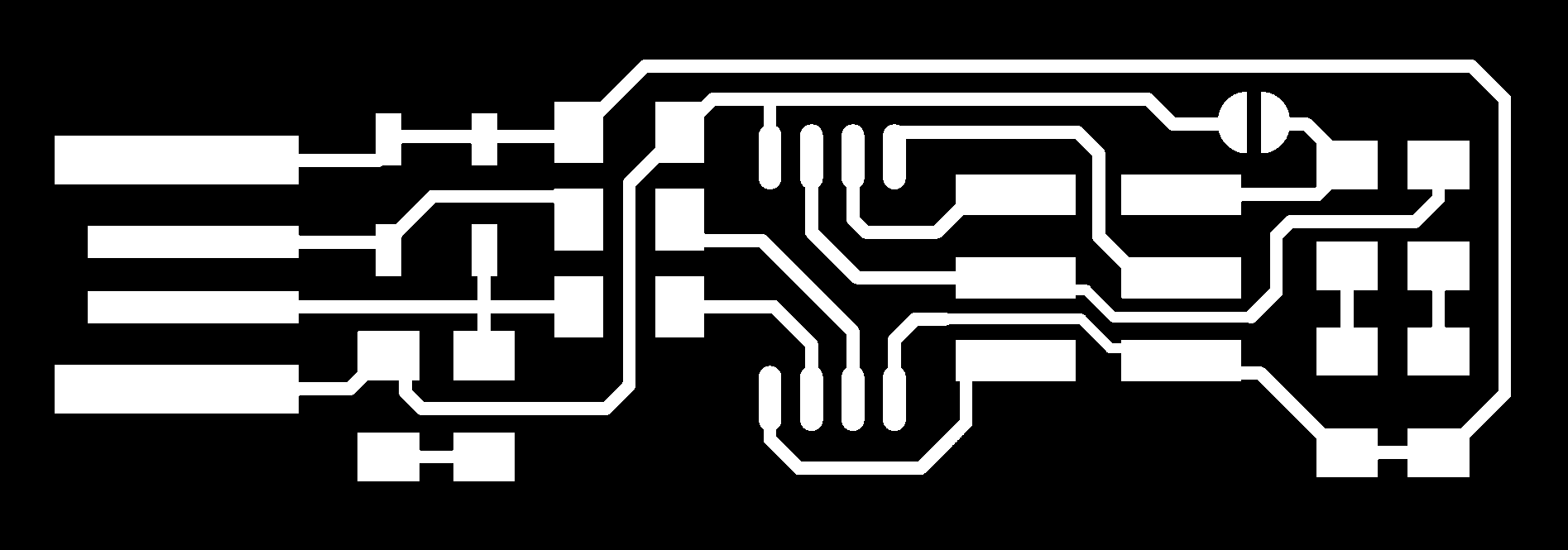
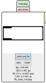
> Once you’re there, you can change the default settings to put your own. We’ll start with the inline traces. Upload your png file in the “read png” module.
You can download the two files here :
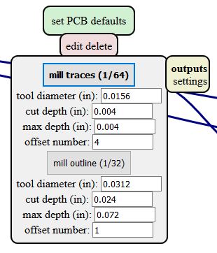
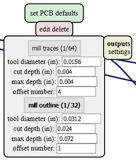
> We uploaded the trace file of our PCB. In the “set PCB defaults” module, just select “mill trace 1/64”. Don’t change any value.
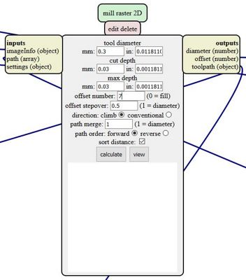
> Now we have to put the settings of our drill in the “mill raster 2D” module.
> We have to setup the offset of our milling machine in the “Roland SRM” module.
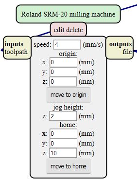
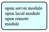
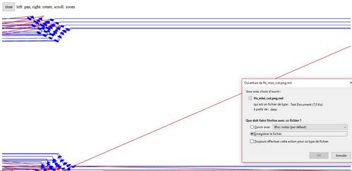
> We have one last thing to do before launching the calculation of our PCB routes. We have to add a module that will automatically download in your computer the rml file once it’s done. For that, right click close to this last module, and choose “modules”.
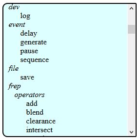
Then “open server module”
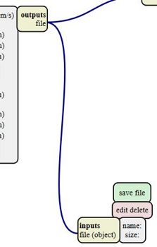
Then select “file > save”.
The module will appear on your page. Click on “inputs” and then “outputs” to connect the two of them together.
Now we’re all set, go back to the “mill raster 2D” module and click on calculate. Here’s what will appear in your module :
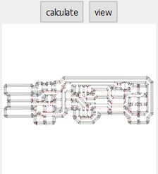
A window will automatically open and show you all the routes of Brian the PCB. Really cool to observe :)

> Now we have to do the outline traces. Easy peasy, just do the same process as shown before, just up to date some settings as you can see below, and here's the result :
Step 2 : milling Brian the PCB
Now that we have our file, we just have to upload it to the machine and… well machine it :)
What is the process to use the milling machine ?
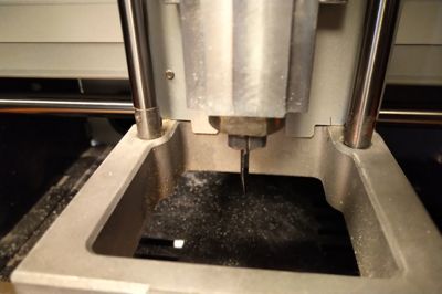
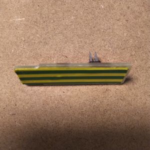
1) First thing first, you have to make sure you have the proper cutter installed. Here, we need the V shaped cutter.
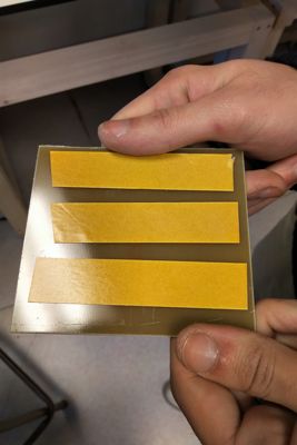
2) Then, you have to install the copper board on the plate. Make sure to glue it with some tape (be careful that there is no bubbles under it, so it won’t deform your board).
3) You have to adjust the parameters of the Roland. The machine works on a 3 dimensional object, so on three different axes : X (right and left horizontal), Y (up and down vertical) and Z (up and down the plate).
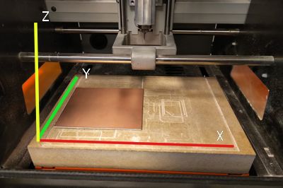
Before starting to mill, you have to define your origin axis. This means that you have to tell the machine where the cutter should start, and where your copper plate is so the cutter won't go too deep or not enough.
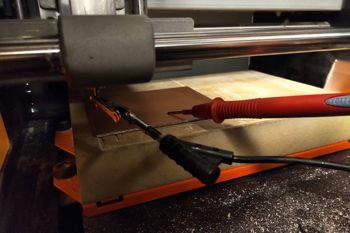
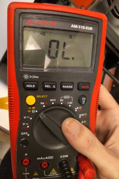
To do the Z setting, you need a multimeter. You take the black crocodile wire and attach it to the cutter, and the red one is used to test the copper. You can do it alone but it's easier when you're helped by someone.
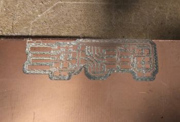
4) Once it is adjusted, just launch the machine and wait. Take a close look at the beginning of the milling and do not stay too far, in case there’s a problem ! If everything goes right, you should have something like this at the end :)
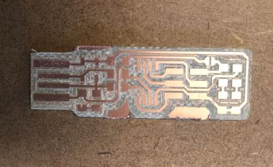
5) Repeat the same process for the cut. You’ll have to change the mill tool, here we’ll use a straight one. Since, you changed the tool do not forget to do the Z again. And voilà !
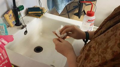
Before soldering, don't forget to clean your board so there's no dust on it. Otherwise, you'll have trouble when you'll solder your componants. I used acetone.

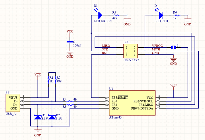
6) Now that it is bright and shiny, you have to solder all your components. Here is the list :
- 1x ATtiny45 or ATtiny85 (I used ATtiny85)
- 2x 1kΩ resistors
- 2x 499Ω resistors
- 2x 49Ω resistors
- 2x 3.3v zener diodes
- 1x red LED (I used a white one, didn't have a red one)
- 1x green LED
- 1x 100nF capacitor
- 1x 2x3 pin header
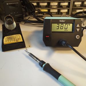
I used a Weller soldering iron, that I let heat until 380°. It's not too warm, not too cold, and I find it the right temperature to do my solderings.
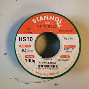
I also used a 0.3mm tin.
I found it really useful to have Brian's schematics opened on my laptop during my soldering, especially to know which direction's I had to solder the leds.
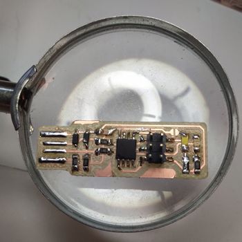
Once it’s done, here is what it looks like :
Step 3 : programming Brian
Our friend Brian is bright and shiny, with all his components. But unfortunately for him he was born with no brain, so we have to put some programming into him so he can start to think !
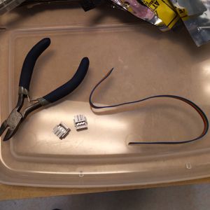
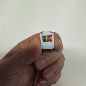
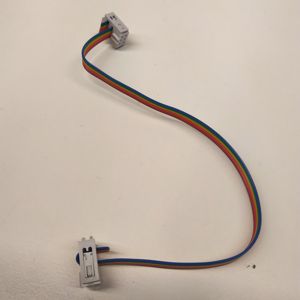
Before everything, and in order to put some code in my Brian, I have to use a ribbon cable (or rainbow cable, as I like to call it) to connect it to my computer. Luckily for me, I have everything here to build my own. It's really easy. Here are the steps down below :
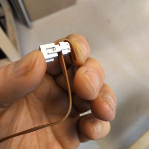
Once you have your ribbon wire, put your Brian and connect it into a usb hub. Why is that ? Because most of modern computers can read USB 3.0 but have trouble reading older/DIY ISPs. This way you're sure not to have a problem connecting your ISP just because of your computer connections.
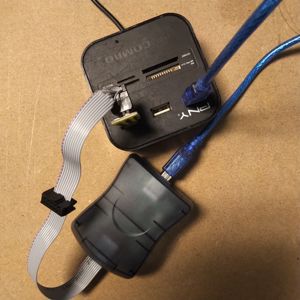
Another piece of advice : put on some tape on the back of your ISP, so it is thick enough to connect well.
Then you can go to the programming part. I strongly advise you to follow (just as I did) the steps described in Brian's biological dad's documentation : http://fab.cba.mit.edu/classes/863.16/doc/projects/ftsmin/index.html#assembly
What did I learn from it ?
First advice : NEVER USE WINDOWS TO PROGRAM YOUR BRIAN
It was a real pain in the a&!* ! I actually spent a whole afternoon just trying to install the sofwares needed, and never been able to program it. If you can, use or borrow someone's computer that is on Linux if you want to program it without too much trouble (#thanksLeoforsavingmefromdespair).
When I was on Linux, things went actually pretty smooth. Just one thing to be careful, coz I forgot it the first time. In the settings include the correct ATtiny name, I used an ATtiny 85. It won't work if you don't do it.

I just had two issues :
-
Soldering problems : one of my zenner diode was upside down. I had this error message :
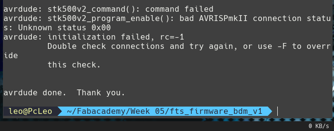
I had to unsolder the zenner diode and then solder it again. And it worked ! :) -
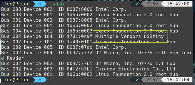
The last step of the programming : the "reset disable" part didn't seem to work. To solve the problem I erased the initial program and uploaded it again. And it worked perfectly ! You can see him appear on the screen :)
Wanna try by yourslef ?
Here are all the links to my files, feel free to download them :
| Name of the documents | Link to download |
|---|---|
| Brian the PCB | Cut RML File |
| Brian the PCB | Traces RML File |