Week 14
Network and Communication
MOOD OF THE WEEK

Hard to get back to work after an almost two weeks break ^^' Especially with this week I kinda feared coz I'm not really at ease with electronics.
Once again I started something I couldn't finish and had to go back to do another thing last minute... the "one day less" thing also didn't help correcting what could be corrected :s
So as expected, it was difficult... and I didn't succeed. I understand perfectly the theory, how everything is supposed to be working. But couldn't get a proper result on my own ^^' Hope next week's gonna be better !
Network and Communication
This week's assignments :
- Group assignment
- send a message between two projects
- Han Solo assignments :
- design, build, and connect wired or wireless node(s) with network or bus addresses
Group Assignment
Here is the link to our documentation for the group assignment :
Han Solo Assignment
Plan A : ESP8266
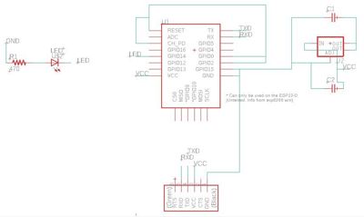
Designing my board
Here is the pinout of the ESP 8266
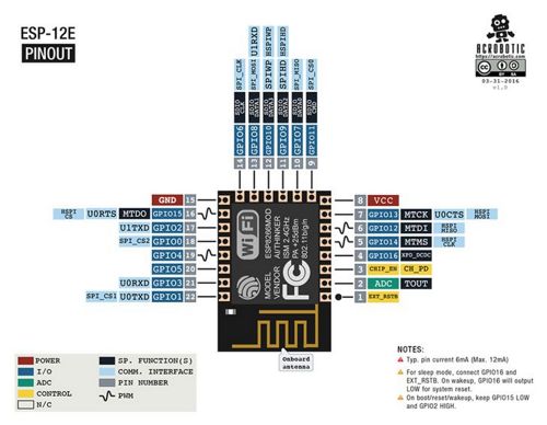
And here is the datasheet : https://wiki.ai-thinker.com/_media/esp8266/a014ps01.pdf
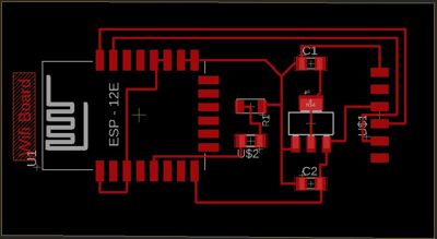
Designing my board
For this assignment, I cheated on my fabacademylong partner the ATtiny and decided to try using the ESP8266, here the ESP-12F version.
In order to design my board, I had to download an Eagle library to get the component print : https://github.com/wvanvlaenderen/ESP8266-Eagle_Library
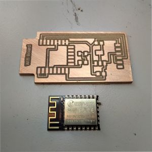
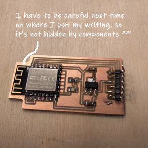
Here is the board milled and soldered. Looks pretty neat !
Programming my board
For this assignment, I cheated on my fabacademylong partner the ATtiny and decided to try using the ESP8266, here the ESP-12F version.
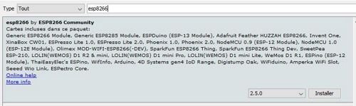
To be able to program this board, I have to add a new library to the Arduino IDE. You just have to go to “preferences” in your IDE and copy paste that line : http://arduino.esp8266.com/staging/package_esp8266com_index.json. Just like we did to add the ATtiny library some weeks earlier !

Then go to “Tools”, “Type of Boards”, “Board manager”, and search for “esp8266”. Click on “install”.
But since everything is complicated in the Fabacademy, I found out that I shouldn’t just have followed the traces Neil made, there’s a whole lot stuff to understand about switching some GND to some other thing. I’ll check it out later, now I need to have something to show for next tuesday ^^’
I understood that while looking at the wiring between the ESP and the Arduino in those tutorials :
- https://www.fais-le-toi-meme.fr/fr/electronique/tutoriel/programmes-arduino-executes-sur-esp8266-arduino-ide
- https://dzone.com/articles/programming-the-esp8266-with-the-arduino-ide-in-3
I don't have that much time left, what can I do ?
After talking to Adel, apparently I can just connect two boards between them and make them communicate and interact to validate the week.
Plan B : Hello Wallou - connecting two existing boards
Programming my boards
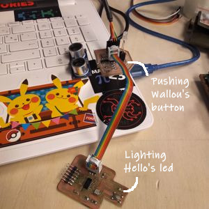
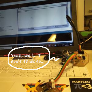
I used Wallou and my Hello Board. The idea : pushing Wallou’s button to light up the Hello Board’s led.
First, let's try to see if we get any result from the FTDI, before even trying to blink anything. I found a code made by a student from last year, where he made a communication between the boards and the monitor from the Arduino IDE. Let's try to upload it !
What are the boards supposed to do? The master board is supposed to send back "Hey, I'm the master" to the monitor, and the slave board "Hey, I'm the slave board".
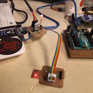
First, I want to be sure that they both work when connected together, no short circuit. And at first, when I connected my Hello slave board to my master Wallou board, the master's led would turn off. Fortunately I didn't have to look too far to understand why it didn't work. I just connected it upside down, and provoqued a short circuit ^^'
This said and fixed, at least when I connect both of them together, both my leds turn on (even if doesn't mean it does anything together, just that it's well "electricity fed". But at this point there is no small victory ;))
Downloading the right library
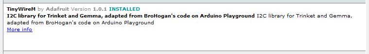
To make this communication thing work, I have to download two libraries called TinyWireM and TinyWireS(one for the master and one for the slave).
To upload them, just follow the same steps as described before.
So, let's get into it.
So, my boards work seperatly, I can upload the code now... but my attempt to communicate and network doesn't seem to be working :s I just get some question marks back as a result, no message at all.
Here's a screenshot so you can see exactly what happens on screen.
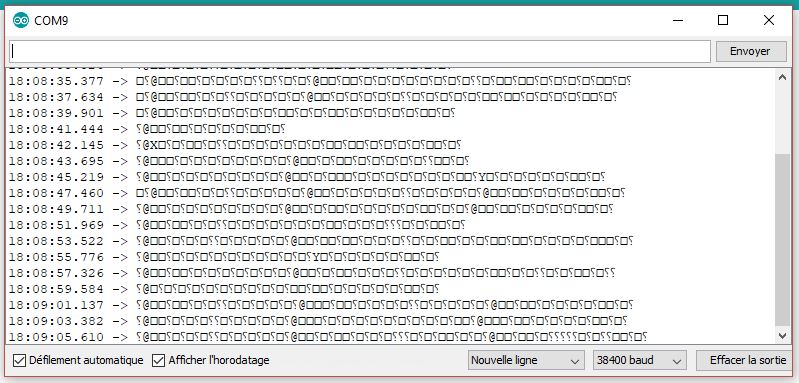
It clearly seems to be a clock problem, coz when I change baud rate I get different kind of gibberish. I have to dig into this to try and make it work better.
UPDATE : OUPS, DID MY WEEK AGAIN !
As you saw earlier, I didn't succeed in doing this week properly in the time given :s But it's not a reason to give up ! I did it again later, and this time it worked :)
I used a bluetooth component that I added to my Hello Board (I did a new one since I finished the assignment afterwards and the other one had a connexion missing. I prefered to have a clean Hello Board ^^), and could communicate with it ! Let me show you how it works.
Discovering the bluetooth component
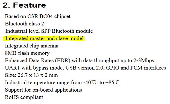
I used the same component as Madjid, the BC-04 BK, this way he could explain to me how it works. But before that, let's take a look at the datasheet of the bluetooth component.
The good thing is that it has the bluetooth 4.0 protocole, and it can be a slave or a master. I will use the slave mode.
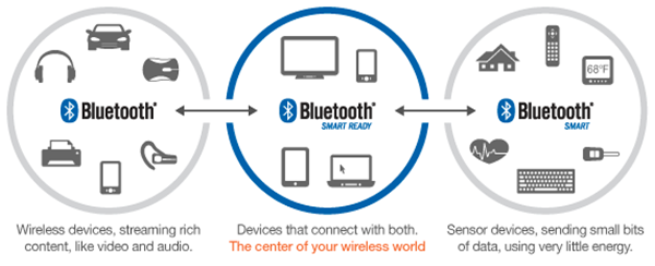
By looking out on what is the bluetooth 4.0 protocol, I found out that one of its main advantage was that is is low energy but kept the same range of action. It is an alternative to the classic Bluetooth protocol.
The problem is that it is not retrocompatible, which means that devices compatible with the Bluetooth 4.0 are not compatible with the previous versions. But there is another Bluetooth device that makes the connections between those two, and it's the Bluetooth Smart Ready !
Here is a table of comparison between the classical Bluetooth and the Bluetooth Low Energy :
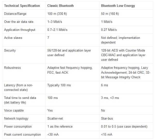
Source : https://blog.groupe-sii.com/le-ble-bluetooth-low-energy/
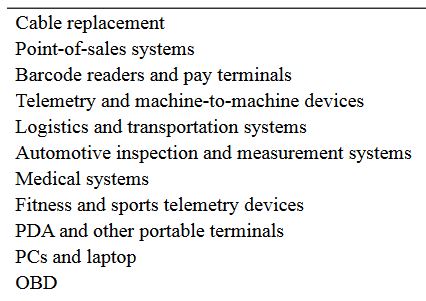
I also see that there is a lot of application fields (this is confirmed by looking at the datasheet), so this could be interesting to know how to use for future projects !
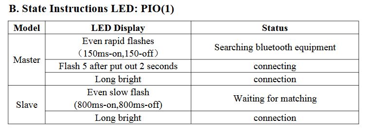
I also see that there's an integrated LED in the component, it will be easy to know if it's working or not !
Okay, now that I know a bit more about my component, let's try to make it communicate with my board !
Connecting the bluetooth component with the FTDI
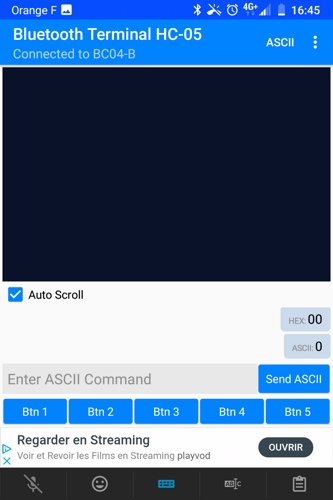
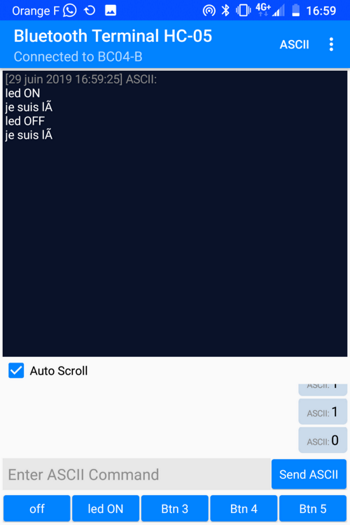
To connect my bluetooth component with the FTDI of my Hello Board, I use the Bluetooth Terminal HC-05 android application on my phone. You can download the application directly in the app store : https://play.google.com/store/apps/details?id=project.bluetoothterminal&hl=fr.
Once the app installed, here is what it looks like when it's open :
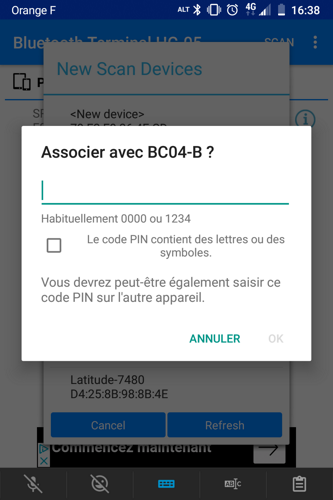
Now I have to scan and pair the app to my device, to be able to send informations. I have to enter a pin code, which is easy : 0000.
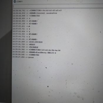
I can see the BC-04 ! :)
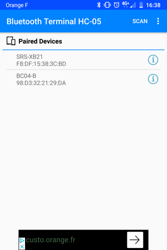
I can see the BC-04 ! :) Now I have to make sure they communicate right. I'm sending a word from the phone to the computer by writing down the message in the app and pressing the "ASCCI" button.
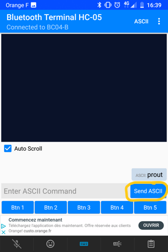
It works ! :)
I also tested by sending a simple '00' by pressing the button 1. LIke previously, it works also !! :)
Connecting the bluetooth component with the board
I want to be able to control my board and switching on a LED with it by pressing a button, and switch it off with another button.
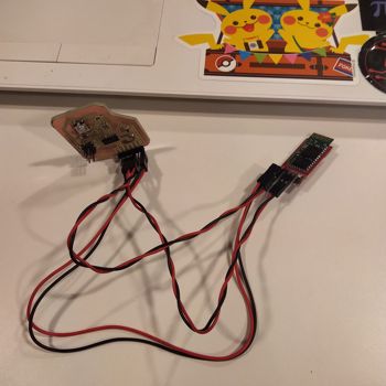
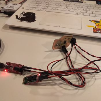
The board and the bluetooth are connected by four wires : RX, TX, 5V and GND.
First I need to use the FTDI to upload a simple code, and see if it sends well an information.
I uploaded this code I made to make sure my board communicates well in serial :
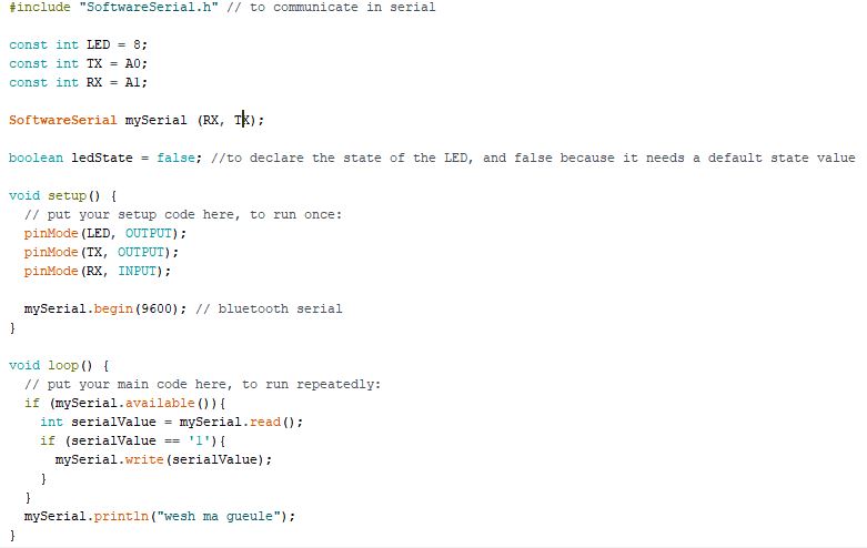
It does ! :)
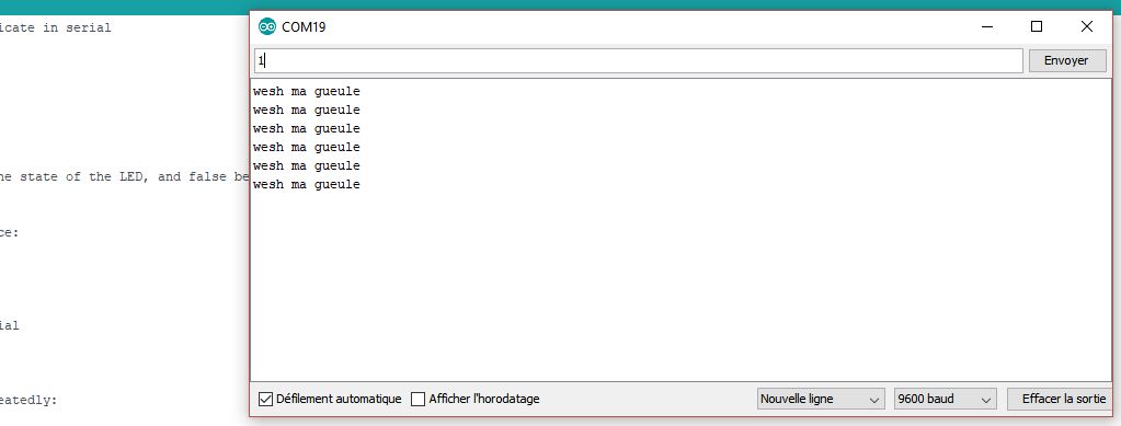
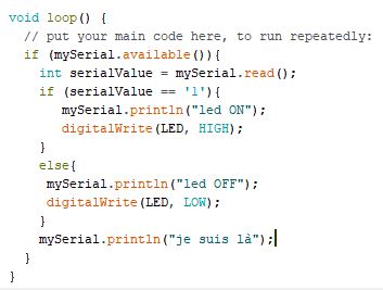
I also tested if I send a message in the monitor, does it print well. I changed the code a bit so when I send '1' in the monitor, it sends a message back. It works also ! :)
Now I have to test if it works with the bluetooth component !
Everything falls into the application and programming the buttons. I won't show again how I do it since it's exactly as in the first part of the documentation, you get the drill :)
I almost forgot, I need to change the wiring a little bit. I connect my serial port on my board to the bluetooth component. And the FTDI will power the board by just being connected in GND and VCC.
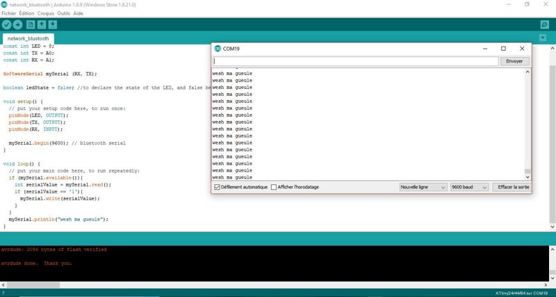
Changed the code a little bit :
Let's see if it works now ! And actually..... it does !! :D
Wanna try by yourself ?
Here are all the links to my files, feel free to download them :
| Name of the documents | Link to download |
|---|---|
| ESP8266 | Eagle board file |
| Attiny45 master | Eagle board file |
| Attiny45 slave | Eagle board file |
| Bluetooth code | Arduino file |