Week 8
Something Big is coming !
MOOD OF THE WEEK

This week was pretty cool and I was looking forward to it ! I actually had the idea for some time now and I'm happy to finally be able to do it :)
Since I didn't have enough time to do it in the same week, I had to split it in several weeks. But the important thing : I have my GOT table !! :)
Let's do someting big !
This week's assignments :
- Group assignment
- test runout, alignment, speeds, feeds, and toolpaths for your machine
- Han Solo assignments :
- make (design+mill+assemble) something big
Group Assignment
Here is the link to our documentation for the group assignment : http://fabacademy.org/2019/labs/sorbonne/group_work/computer_controlled_machining/
Han Solo Assignment
This is what I do : I know things and I make stuff !
This week is a cool one, we have to make something big :) As I’m a big fan of Game of Thrones, and since april is coming, I want to make a table for my couch, so I can work easily without breaking my back :)
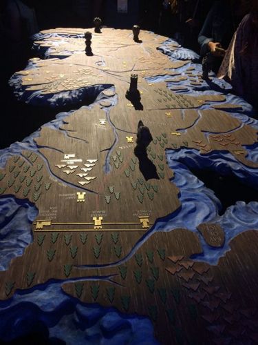
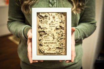
Step 0 : inspiration
I found a lot of inspiration on Pinterest :
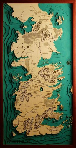
I wanted to drill the map directly in the main wooden plate, but I don’t have enough time so I’ll use the laser cutter to do the different layers for the map. And I’ll use some epoxy resine to put in it so the plate stays flat.
But first things first, let’s do the wooden plate and the feet.
Step 1 : Milling the main plate and the feet of the table
A/ Drawing the table
I used Inkscape to draw my table. First the feet.

Then the main plate :
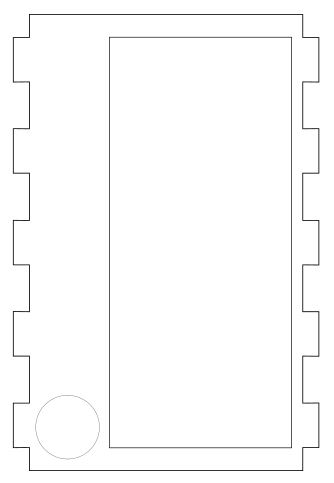
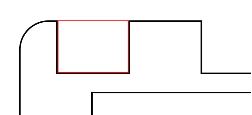
To be sure the notches work, I made them first in red, saw if it fit with the notches of the feet and then copy/paste them in the right document.
To help me I got inspired by this image, that helped me understand how to calculate press-fit joints :
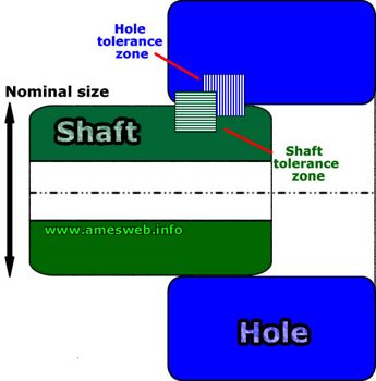
I didn't need it here, but for bigger projects you can also use a fit calculator to help you calculate the right fits.
Now that the drawing is done, I have to save them as DXF files (for VCarve). Let’s mill it :)
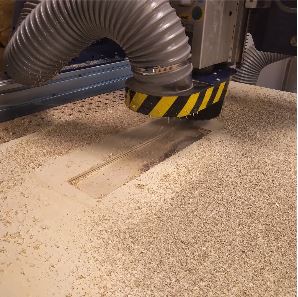
B/ Milling the table
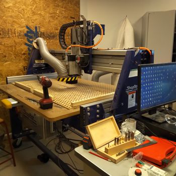
We use a Shopbot at the Fablab. It’s like the small Roland… but in very big ^^
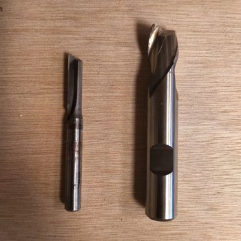
As tools, I used a 6.35 mm (with one tooth) and an 18.5 mm (with two teeth) drills.
Why did I use different drills ? Because I have a big pocket in my table (where I’ll put my map) and it would take way too long if I stayed with the same tool as the rest (actually more or less 10 min with the 18.5 mm vs 1 hour with the 6.35 mm). Sometimes it’s worth taking 10 min to change a tool than wait way too long close to the machine to watch it work !
To communicate with the machine, I have to use the software VCarve. As mods for the Roland or Cura for the 3D printer, VCarve will translate the drawing I made in instructions for the machine.
C/ Creating your VCarve file
Once in VCarve, you have to open your DXF file. I’ll show you how it works with my table’s feet ^^
You want to know step by step how to use VCarve ? Since it was a bit long, I put everything in this tutorial. Enjoy ! :)
There you can find all my settings for the table I've made :)
Since I used a one tooth straight bit of 1/4", here are the speed and feed I've set in VCarve :

Stéphane showed me this data recommandation chart for soft plywood from Onsrud to help me calculate the feedrate.
Our local instructor never explained this to us, so I'm not really confortable with the operation but I'm gonna try at least for one tool :)
By reading the document I found out that the formula to calculate the feedrate is: Spindle speed (RPM) x number of cutting edges x chip load.

The chipload for the endmill I used was 0.0157, the spindle speed we use here is 6000rpm and so the formula gave me a 94.2 inches per minute feedrate, which is 40mm/s.
Why is it important to know how to calculate the right speed and feed ?
The right speed and feed vary depending on the material. If the spindle is too fast but the feed rate too slow, the endmill will heat up or even burn the wood. If the feed is too fast compared to the spindle size, the endmill might break because not enough material is chiped away.
D/ Settings for the Shopbot
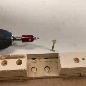
First, I fixed the plank of wood on the table by putting screws at the edges.
Then I can enter the settings for the Shopbot. As I have to do when I use the Roland, with the Shopbot I have to set the X, Y and Z of the machine. For this I use the Shopbot3 software.
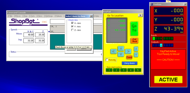
The 0 for the X and Z are done the same way as for the Roland. Place your drill where you want it.
For the Z, you have to take the copper colored crocodile clip and put it on where your drill is attached, and put the metal small plate under the drill. Just press the “Z” button on the yellow board and it does it on his own :)
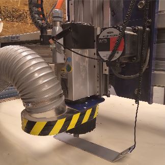
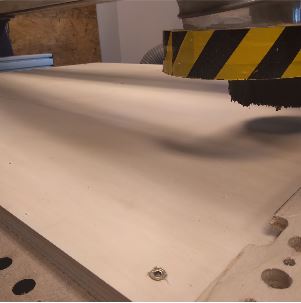
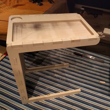
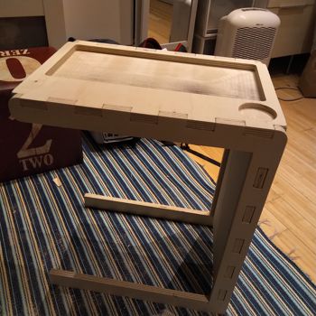
Okay, everything seems set. Let’s do this ! :)
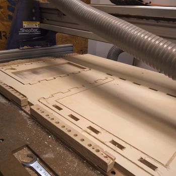
I'm really happy with how it came out !
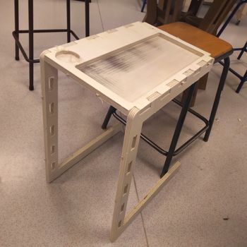
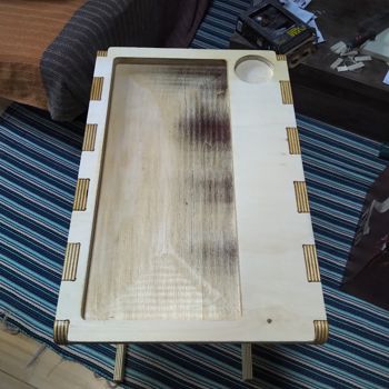
Step 2 : Finishing the table properly
Now, I have to fill my table with the topographic map I did on the laser cutter.
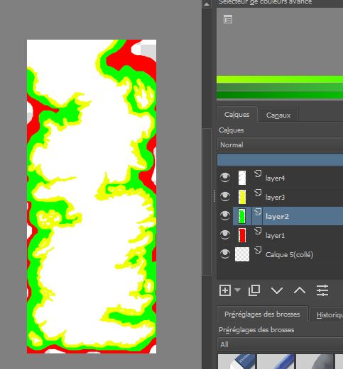
This was a tricky part coz I had to redraw the all map of Westeros ^^'
For this, I used Krita and Inkscape. I had to do it layer by layer. First on Krita, as you can see on the picture below, I did the map of Westeros and then added the under layers.
Then I uploaded the map on Inkscape to be able to cut it in the laser cutter.

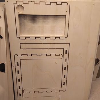
I did a first test to be sure everything was okay and fit well.
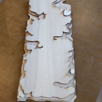
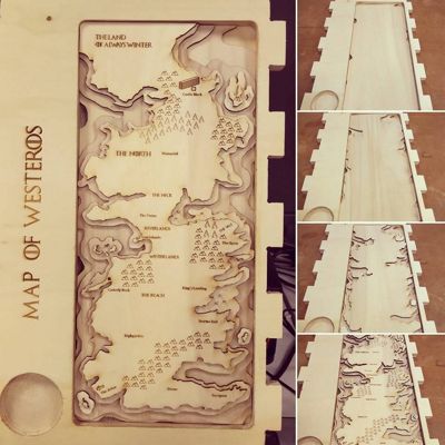
Here is what it looks like once it is cut, glued and I have engraved the title :)
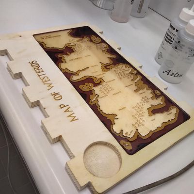
Once I had everything, I painted the different layers so it would be more beautiful, and then added some Epoxy resine so the platter remains flat and I can work on it :)
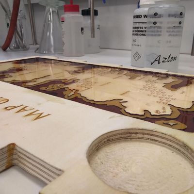
If you want to have more info on how epoxy works, please check my molding and casting week :)
Wanna try by yourslef ?
Here are all the links to my files, feel free to download them :
| Name of the documents | Link to download |
|---|---|
| Topography | Layer 1 file |
| Topography | Layer 2 |
| Topography | Layer 3 |
| Topography | Layer 4 |
| Furniture | Table's feet |
| Furniture | Table's plate |
| Decoration | Table's back decoration |
| Decoration | Table's under bock |