12. Output devices
Add a sensor to a microcontroller boardthat you have designed and read it
Idea
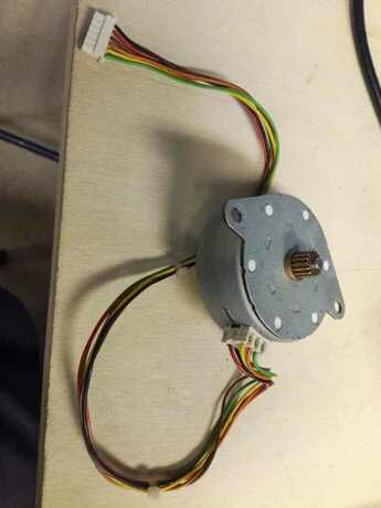
- Work with stepper motor for my final project
- Get example from Neil board
- Use an old motor of the fablab
First try
Electronics
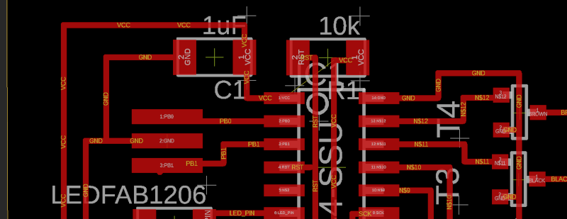
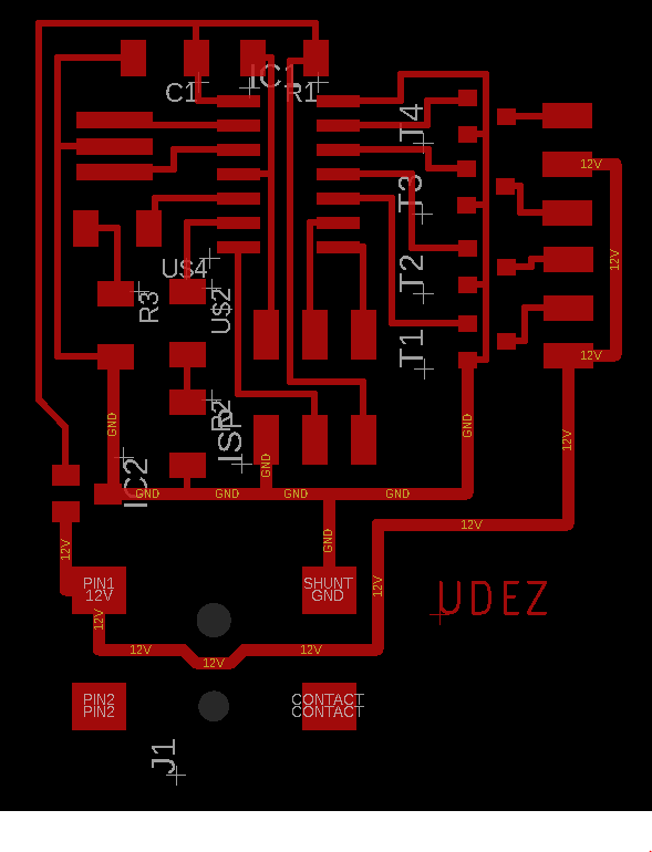
Eagle design
- Start from neil design
- Adapt the regulator voltage to the component that we have in the fablab
- Add Led to facilitate the debug of the board
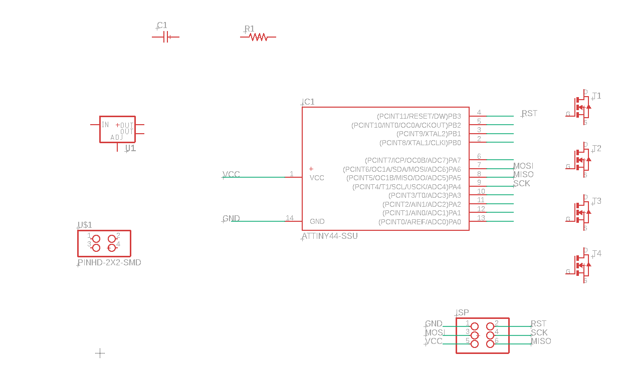
- I made the connexions
- And for sure, I add my company name
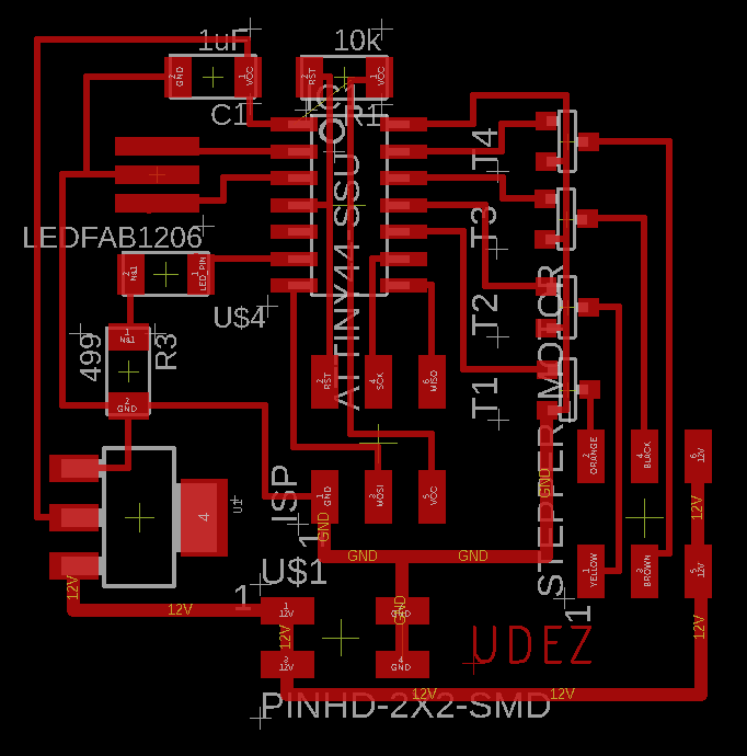
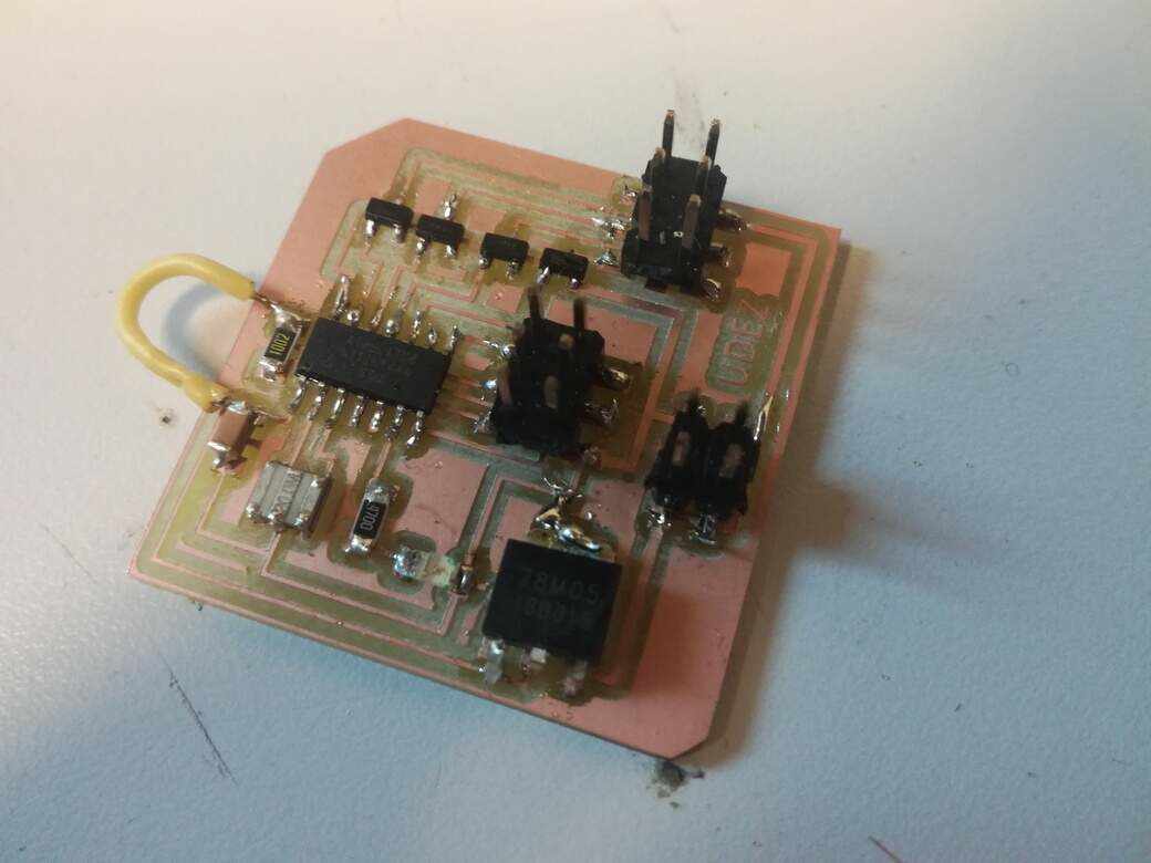
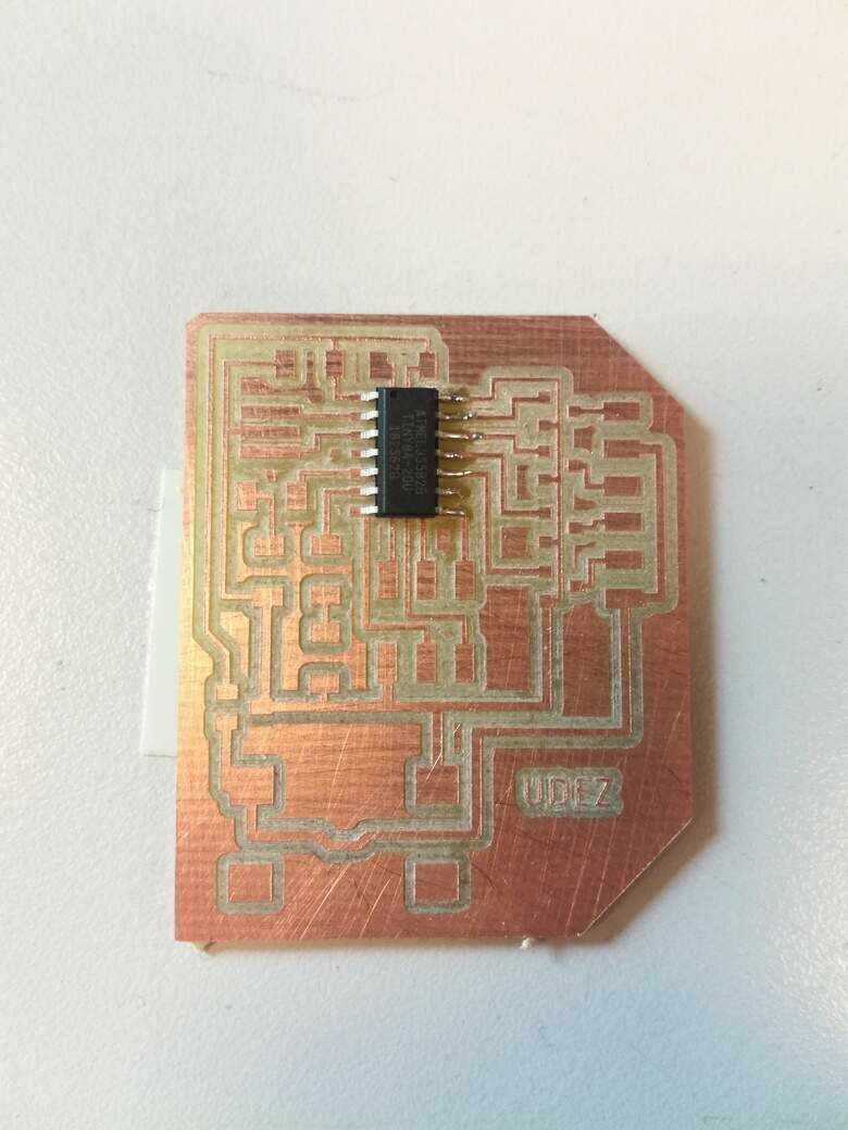
PCB Production
- Milling, using the same parameter of the electronic production
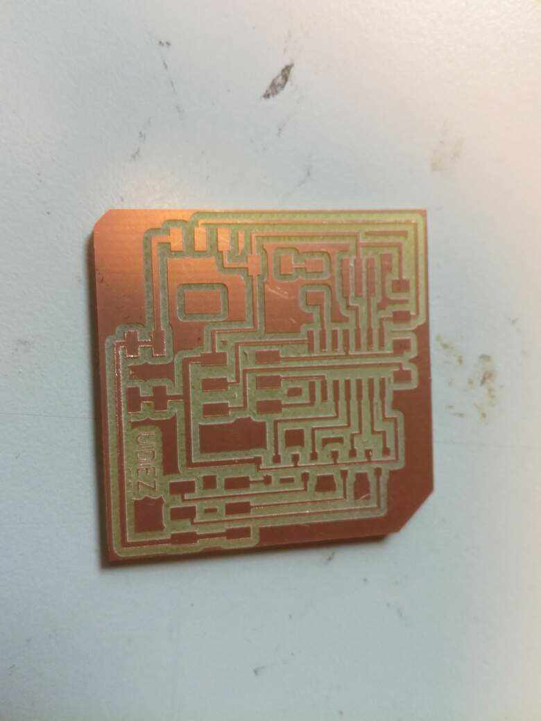
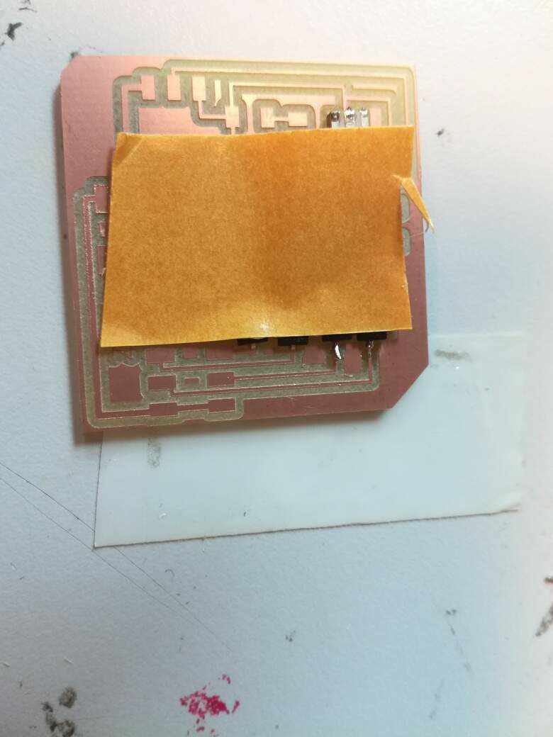
- Sold by starting from the attiny44
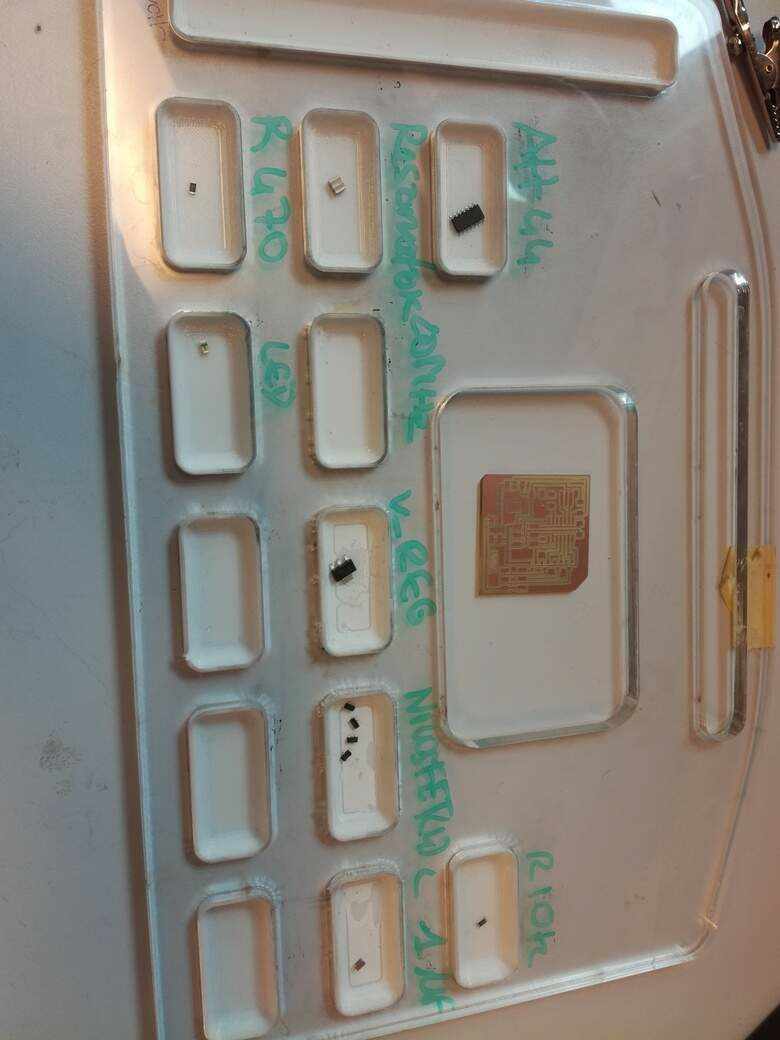
- And add the others tiny component
- add some tape to fix mosfets in the board will help to solder them
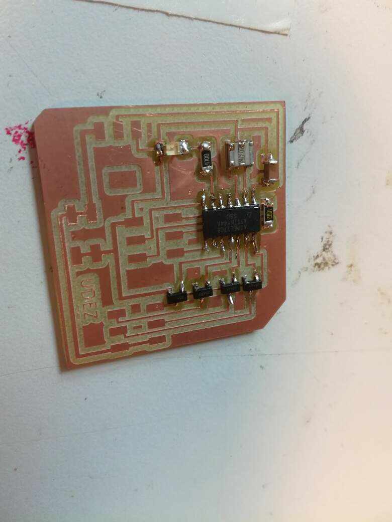
Test the code
- Using the same blinking code of embedded programming
- Nothing to do, I can't upload the code
Where is the bug ? 🐛 👀
The FabISP ?
- I try to upload the code with my FabISP
- I thought that was my FabISP the problem, so I try with an arduino it was the same problem
- And to be sure, I try to upload some code in my previous boards with the FabISP and it works.
- So it's not the FabISP
The PCB design ?
- I start by inspect my board in Eagle for each connexion
- And 🙈
- I made a mistake, I forget to connect VCC to the ISP interface
- So I add wires from the right resistance to the left capacitor
- But finally it was not that the problem, because I could'nt upload my code
One of the components ?
- I take the multimeter to test the connexion from the VCC to the GND
- And 🙊
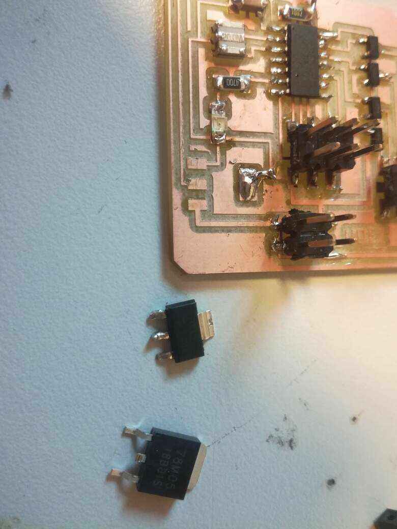
- I made mistake, I didn't see that was not the good reglator
- It was a 3V, I didn't take the time to read better the datasheet
- I saw in datasheet of the attiny44 and normally it can work from 2.7 to 5.5V
- So I change the regulator with new one without the same package
- I made some horrible surgery on my board to adapt it
- But it was worse that the the begining because I don't add the resistor like it's explain in the datasheet, 🙉, so I have 8V now !
- I also made another mistake, I don't choose the right connector for my motor, I would be check before to mill it !
- So I give up the idea to rescue my PCB production 👼 and I decide to design a new board.
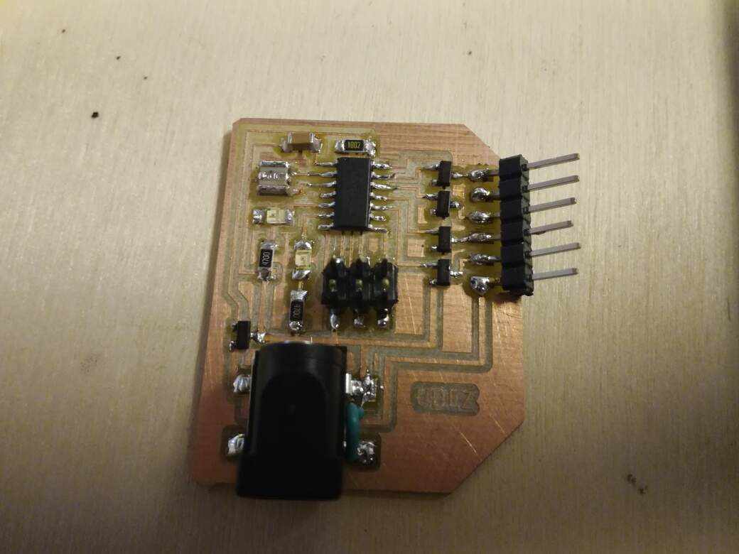
Second try
What's new in the board ?
- Connector for the motor will be aligned instead to be like an ISP
- Using LDO regulator instead the others regulators
- Inspired by Stéphane, I add an alimentation Jack.
- Add new LED, to play with it when the motor turns
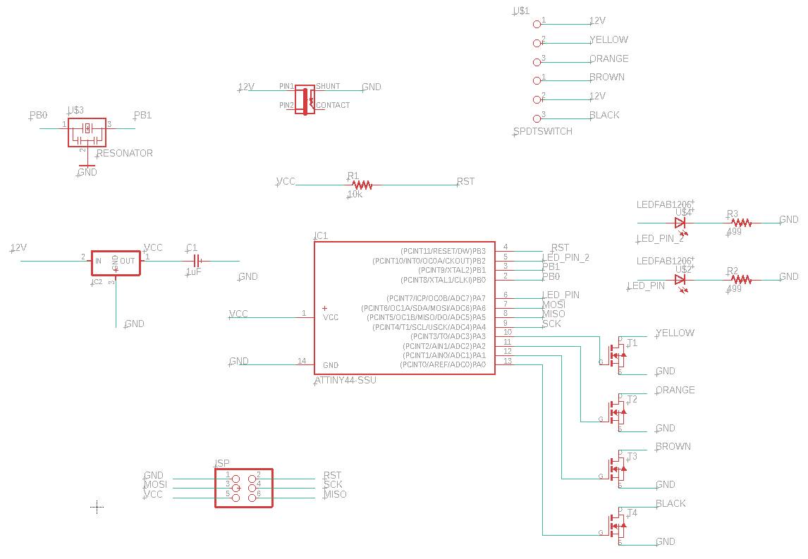
Eagle design
Test the code
Blink test
- The blink test was good
Stepper motor
Code's Neil adapted to my board
//
//
// hello.stepper.44.wave.c
//
// wave stepping hello-world
//
// Neil Gershenfeld
// 11/14/10
//
// (c) Massachusetts Institute of Technology 2010
// This work may be reproduced, modified, distributed,
// performed, and displayed for any purpose. Copyright is
// retained and must be preserved. The work is provided
// as is; no warranty is provided, and users accept all
// liability.
//
#include <avr/io.h>
#include <util/delay.h>
#define output(directions,pin) (directions |= pin) // set port direction for output
#define set(port,pin) (port |= pin) // set port pin
#define clear(port,pin) (port &= (~pin)) // clear port pin
#define pin_test(pins,pin) (pins & pin) // test for port pin
#define bit_test(byte,bit) (byte & (1 << bit)) // test for bit set
#define MOSFET_port PORTA // MOSFET port
#define MOSFET_direction DDRA // MOSFET direction
#define black (1 << PA0) // MOSFET output pins
#define brown (1 << PA1) // "
#define orange (1 << PA2) // "
#define yellow (1 << PA3) // "
#define on_delay() _delay_us(50) // PWM on time
#define off_delay() _delay_us(10) // PWM off time
#define PWM_count 200 // number of PWM cycles
static uint8_t count;
//
// yellow PWM pulse
//
void pulse_yellow() {
for (count = 0; count < PWM_count; ++count) {
set(MOSFET_port, yellow);
on_delay();
clear(MOSFET_port, yellow);
off_delay();
}
}
//
// black PWM pulse
//
void pulse_black() {
for (count = 0; count < PWM_count; ++count) {
set(MOSFET_port, black);
on_delay();
clear(MOSFET_port, black);
off_delay();
}
}
//
// orange PWM pulse
//
void pulse_orange() {
for (count = 0; count < PWM_count; ++count) {
set(MOSFET_port, orange);
on_delay();
clear(MOSFET_port, orange);
off_delay();
}
}
//
// brown PWM pulse
//
void pulse_brown() {
for (count = 0; count < PWM_count; ++count) {
set(MOSFET_port, brown);
on_delay();
clear(MOSFET_port, brown);
off_delay();
}
}
//
// clockwise step
//
void step_cw() {
pulse_yellow();
pulse_black();
pulse_orange();
pulse_brown();
}
//
// counter-clockwise step
//
void step_ccw() {
pulse_brown();
pulse_orange();
pulse_black();
pulse_yellow();
}
int main(void) {
//
// main
//
static uint8_t i,j;
//
// set clock divider to /1
//
CLKPR = (1 << CLKPCE);
CLKPR = (0 << CLKPS3) | (0 << CLKPS2) | (0 << CLKPS1) | (0 << CLKPS0);
//
// initialize MOSFET pins
//
clear(MOSFET_port, brown);
output(MOSFET_direction, brown);
clear(MOSFET_port, black);
output(MOSFET_direction, black);
clear(MOSFET_port, yellow);
output(MOSFET_direction, yellow);
clear(MOSFET_port, orange);
output(MOSFET_direction, orange);
//
// main loop
//
while (1) {
for (i = 0; i < 10; ++i) {
for (j = 0; j < i; ++j)
step_cw();
for (j = 0; j < i; ++j)
step_ccw();
}
for (i = 10; i > 0; --i) {
for (j = 0; j < i; ++j)
step_cw();
for (j = 0; j < i; ++j)
step_ccw();
}
}
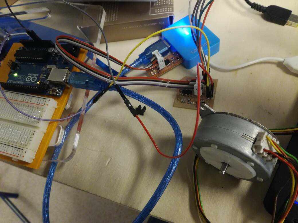
}I uploaded the code using platformIO, the board works and I checked with an multimeter, the variations of courant was effectively distributate as it's describe in the code, however after many tests, I was not able to control the motor. So I decide to debug the hardware motor and see if it's the source of the problem.
To know how to debug a 6 wire motor, I looked a video from youtube where the debugging is well explained. Then I found that the motor doesn't work anymore. When I try to execute the sequences by hand, the motor doesn't have any reaction. Then I try to find an other motor in the lab or in local vendors, they have not this kind of stepper motor. I don't know if it's not an european standard or if the six wires are old models, but I didn't find an other motor.
I don't need especially to buy a 6 wires motor without needed, and I told that I could use DC motor with one of the mosfets board to turn on and turn off the motor, but I know, it's not safe, because DC motors needs zener diode to make sure that the flow is only in one direction, and optionnaly a capacitor for the decharging motor. So I will use the final project to demonstrate an output device, indeed, in the final project I used a small dc motor.
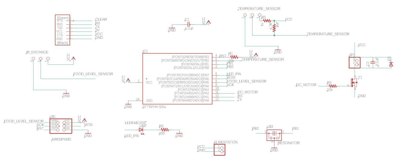
Dc motor in fishsitter
To start the fishsitter board, I take example from some of my previous fabacdemy board, and I choose the microcontroller that I know the most, the attiny84. For alimentation, I want to use an old USB cable that I had, so I just placed two male pin header. And like for all my boards, I add the resonator of 20Mhz, debugging led with the FTDI and SPI interfaces.
Then, I add the end food sensor and temperature sensor from the input device week schematic. Because, I found a small dc motor, seems have a great torque, they are any reference in the motor, so I don't know the voltage input, but I think I will use it it can be from 3 to 6 or 12 V.
Debug input voltage
To debug input voltage of the motor, I take a stablizied alimentation and start with the minimum voltage (3v), I add slowely voltages to see the limit, when I arrived from 5v to up, I did'nt see a big difference, So I think the limit is 6 voltage, I will juste use a 5 volt to keep the board simple.
Motor schematic
Then after some talking with Luc about best practice I maid this schematic to control the motor. My goal is to use the time to take portions food. So I only need a transistor to be able to enable and disable the motor rotation. Then the DC motor should be connected with a zener diode, in this way, we are sure that the courant flow always in the same direction. The capacitor is used to decharg the motor when he stopped. I also add resistance before the transistor drain to prevent short circuit when the pin is HIGH.

Motor routes width
To prevent problems of tension, I choose 24 width for routes. It should deliver more courant in this way. So I update all routes from the alimentation to the motor, included the diode, and the capacitor.


Mods problems
I had some problem, like you can see in the botton, when I generate the rml file using mods. I don't have enought space beetwen the food sensor and his vcc.
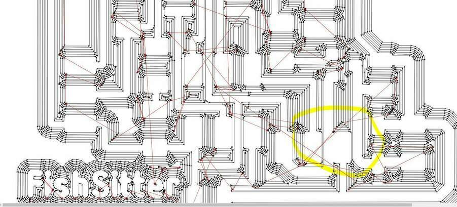
So for this path, I will reduce the route to 20 instead 24 like I mentionned it in the top. But instead to change the routes paths, I just move with few millimetters the routes between the two routes and it works great.

I hope, it will be the same for machining. Finally the board was milled perfectly.
Board schematic
Board traces
Here is the final traces for my fishsitter board.

Board machined
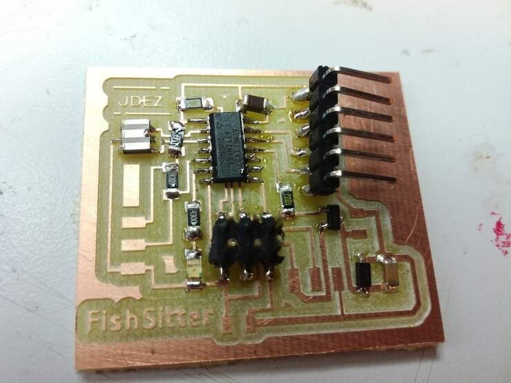
⚠️ I missed to take a great picture with all pins solded before to drop the board in the water, hopefully works again but I fiw some traces with Pistocole
Write the code to test the motor
Using the arduino IDE, I maid a simple delay and I didn't use a function millis (unlike the previous week), to simulate the portion of food giving. In the same time a choose to activate the led when the motor is running (principally for the debug).
/*
  Blink motor

  by Madjid AIT SI AMER
*/
#define LED_BUILTIN A7
#define MOTOR_PIN A2

void setup() {
  // initialize digital pin led and motor.
  pinMode(LED_BUILTIN, OUTPUT);
    pinMode(MOTOR_PIN, OUTPUT);
}

// the loop function runs over and over again forever
void loop() {
  digitalWrite(LED_BUILTIN, HIGH);    // turn the LED on
  digitalWrite(MOTOR_PIN, HIGH);    // turn the Motor off
  delay(6000);                       // wait for 6 second
  digitalWrite(LED_BUILTIN, LOW);    // turn the LED off
  digitalWrite(MOTOR_PIN, LOW);    // turn the Motor off
  delay(6000);                       // wait for a 6second
}
Note, that for the final project I used the function millis, to have better management of even, for more information, please go on the final project note book
Test the motor
Here is one of my first test with the infinite screw and the fishsitter board: