7. Electronics design
Redraw the echo hello-world board, make it and test it.
Eagle design
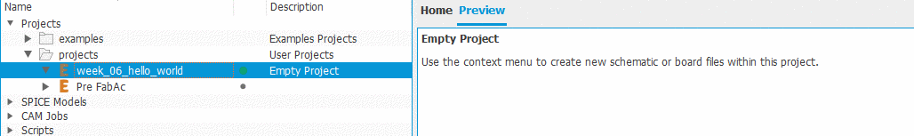
I start by using example gived in the class, and I create new project in eagle and open it.
Get library the fab.lbr library
Before to start, I need to install the fab.lbr library . This library made by member of the FabFundation, contains most of the components we need and we have in a fablab.
Download the library
In Eagle click on the
add part menuOpen
library managerClick on
AvailableFound the library on your computer with the browse function
Click on
Use
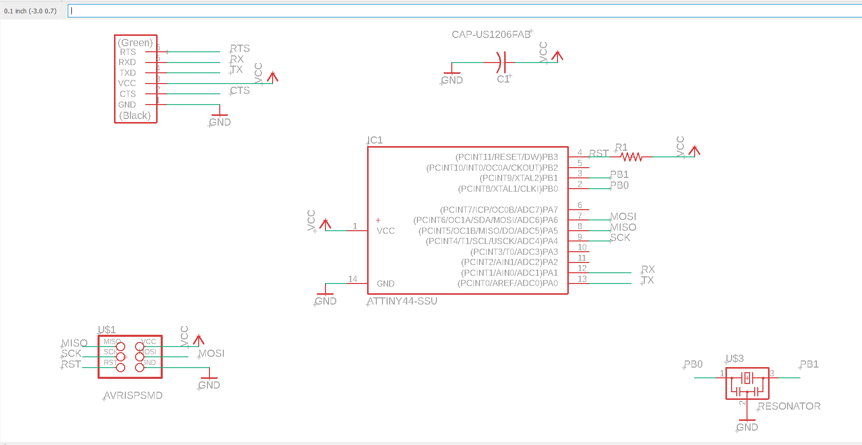
Design the schematic
I create new schematic and now I will prepare the list of the components that I need.
I prepare a list of all the components that I will need (BOM)
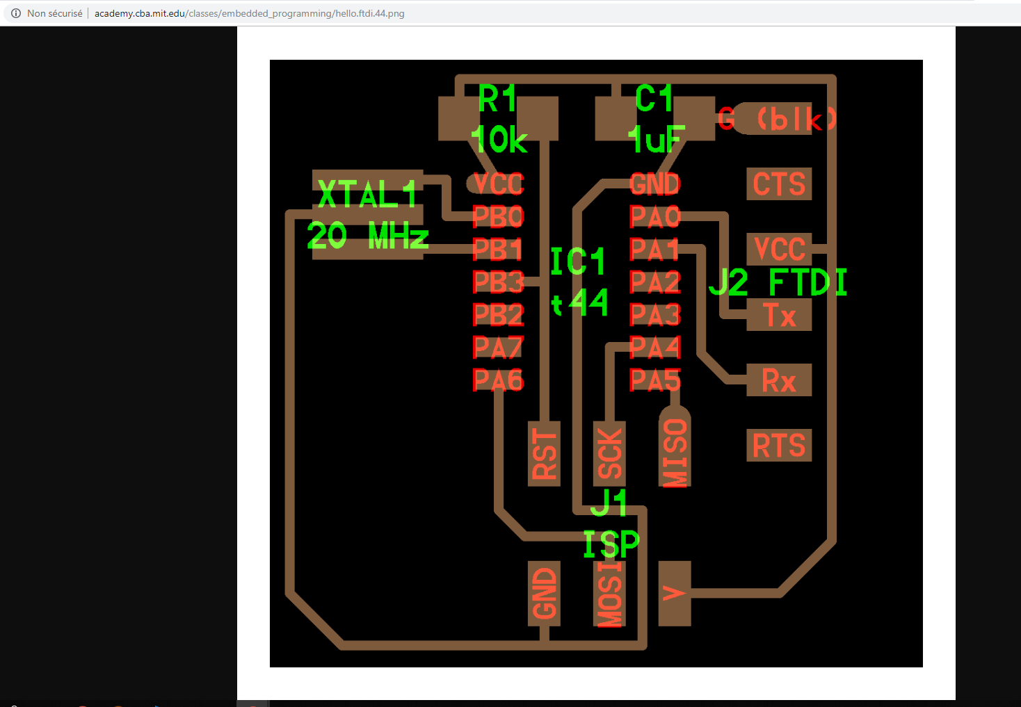
XTAL1 20 MHz: Resonator ...R1 10k: Resistance for the resetC1 1uf: Capacitor ...J2 FTDI: FTDI connectorJ1 ISP: ISP ConnectorIC1 t44: Microcontroller Attiny44
Like the soldering, using the command
add, I start by placing the microcontroller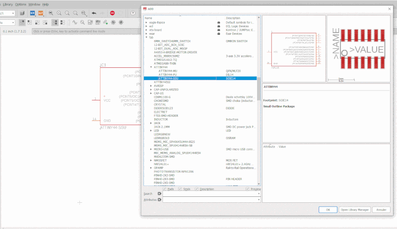
After that I select all the components of my list, I looked attentively when I selected my components, they are mostly defined by there sizes. The fablab recommand to use 1206 size.

I try to add some networks, using the command
Netbut I have so many networks, it's a little bit confusing, I need to learn more about eagle.
After some tutorials
- I start making clean network between my components. Using the command
remove, I removed almoast all the networks.
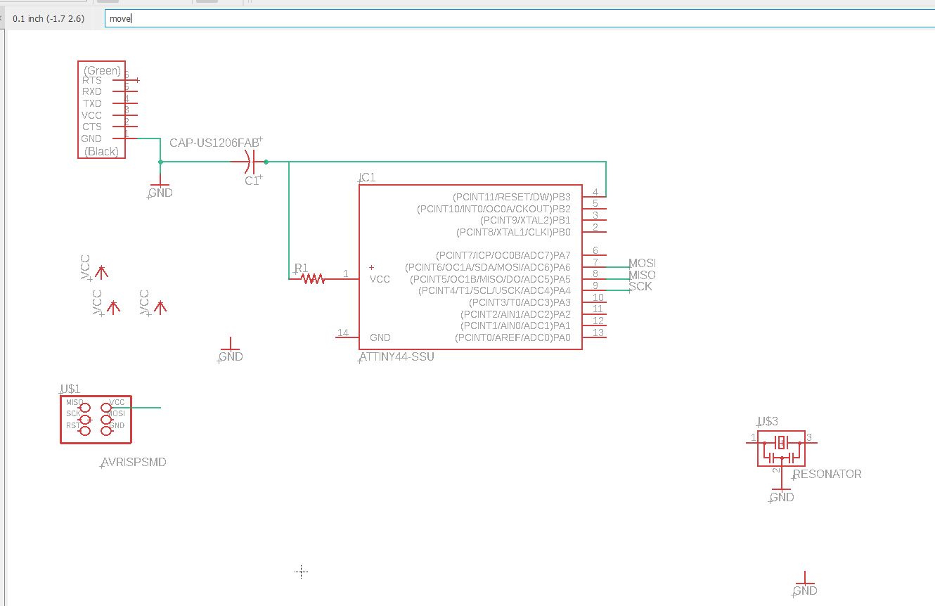
- I placed components
GNDandVCCon each pin. I have used this components to have more clarity on my schematics. This virtual connexions will be connected automatically on the route mode. Another tips like theGNDandVCC, is to use component we will use the naming of networks. It permit to compose each part by functionnality.
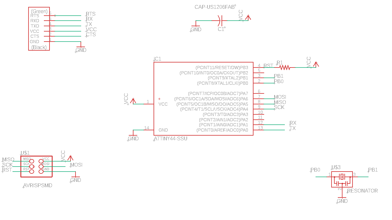
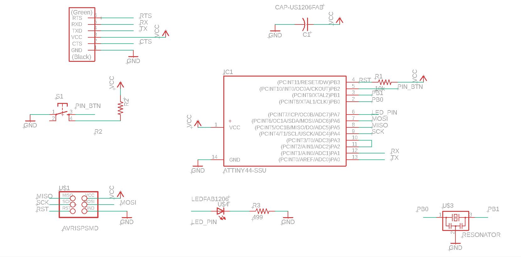
- And the final schematics 😄
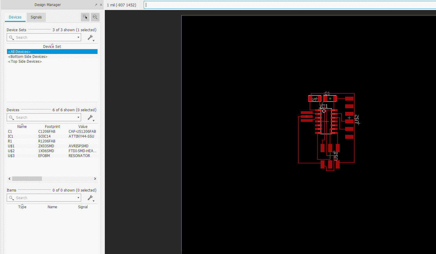
Design the board
Placement of the electronics components
To place the components, we need to select by clicking and moving on the black area. For the placement I was inspired my Neil board. The attiny is placed on the center of the board. ISP connexion on the bottom and the FTDI connexion on the right.

Make traces
To make the traces I used the function route of eagle. When you are in this mode, and you select pin, all he's possible connexions will be red.
On this above capture you can see that in the beggining I maid mistake and I did'nt take attention to the width route. Instead to use 12 width more adapted for our tools, I use the default width, which is 6.
Plus, there is yellow wire helping to see the connexion, I missed also to see it clairely in above capture, so I missed one connexion.
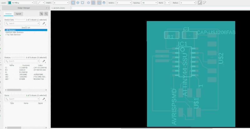
Outlines board
To make the outlines board, on eagle, I switched on the Milling layers, using the checkbox on the top-left. After that I used the polygon tool in the toolbox to define the outlines of my project.
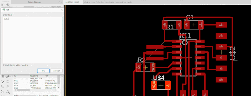
Add logo
I try to import directly from dxf my logo, but it was complicate to set the right dimension, so I decide to create it directly from Eagle.
This board, is quiet diffrent from the previous screenshots, because, I update little bit a board, since I lost a part of my work 😦
Add font
Add route without connexion
Add button and led
Schematics updates
The led must be connected through a resistor around 499Ω to a pin of our microcontroller. Here I choose to name the pin A7 of my Attiny into LED_PIN and because we don't have 499Ω resistor in the lab, I take one of 470Ω.
Connect a button to a micro controller was not easy. To understand how it's work we found a really good documentation.
Basically, it explain that you have to connect the alimentation (VCC) to a pin of your board and when the button is closed the electrical current go to the ground. But be careful to put a resistor beetwen the VCC and your button else when the button will be closed it will create a short-circuit. So I choose to name the pin Attiny into PIN_BTN with one resistor of 10kΩ.
So here is the updated schematics:
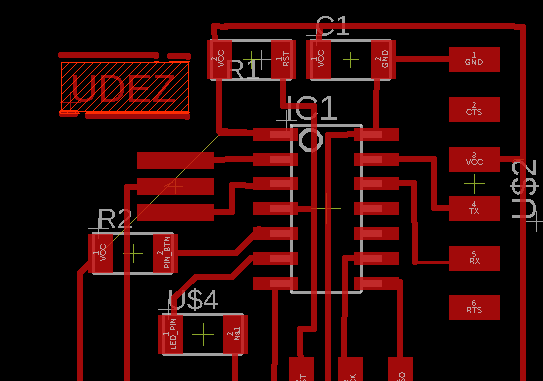
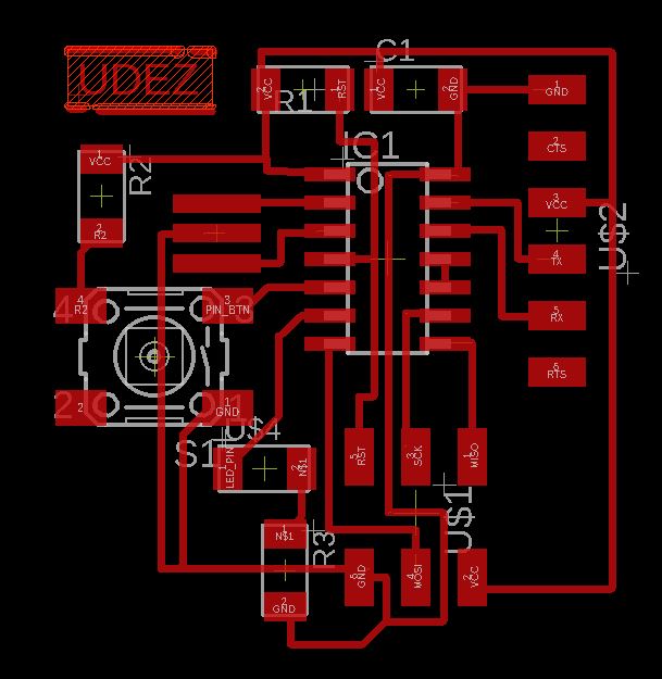
Board updates
After I have updates my routes thickness, from 6 to 24, I start by adding the button with his resistor, and then I added the led with his resistor. I use the properties of components (leds and button), to make one compact board, I made route on the middle of this components, so here you can see the result:
Some tips
Don't forget resistor with the button
I told that the board works, because of the code that I uploaded I was confused,. I missed to add a resistor of 10k between the VCC and the GND. I remaid one board because of this mistake.
Configure the scale of the board
If you want to be more confortable when you move your component in Eagle, you need to configure in the right way your board.
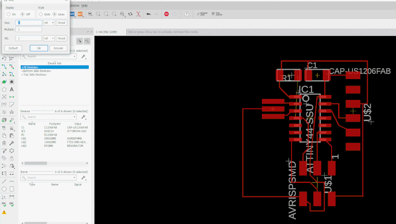
Adjust the route width
You need to be careful when you made th network in your board and to choose the right size of width for route lines. For me it was 12.
Check errors in Eagle
Use Tool > Errors to check if they are no big problem in your design.
Fabricate the board
Preparation
Milling board
I used the same configuration than the last week.
After that, I start the process...
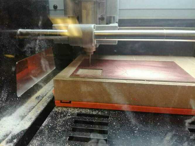
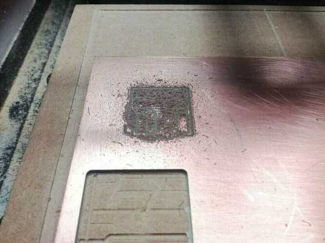
After little cleaning, I decide to check if everything is ok before the cuting, and it seems good 👍
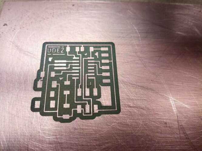
So, I lunch the cutting board 🚀
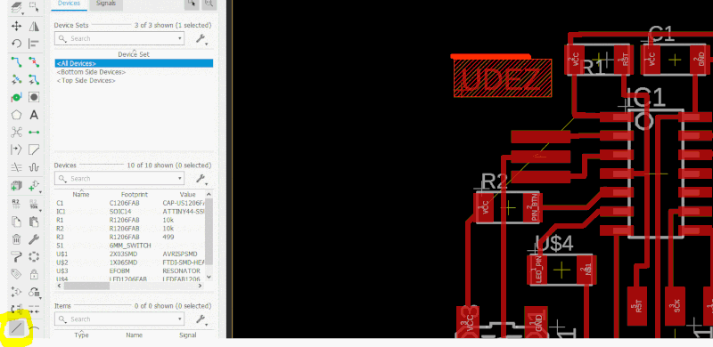
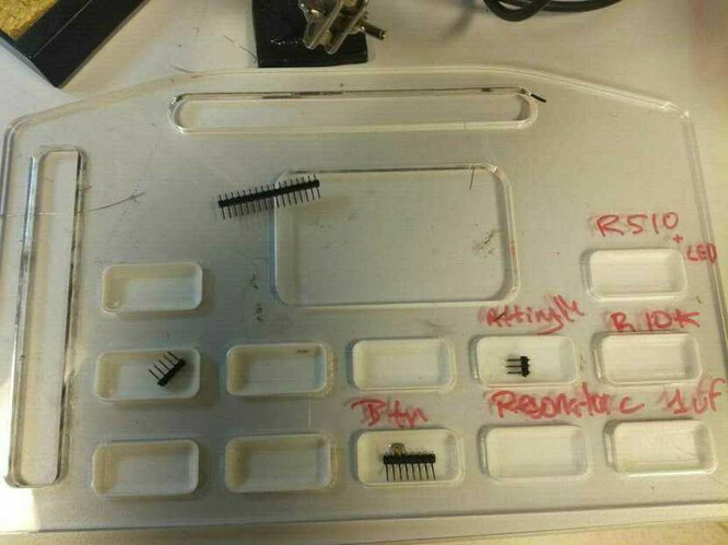
Electronics components
I take the BOM that I export with eagle to prepare all the electronics components before soldering.
Soldering
I start by the microcontroller and the components around it.
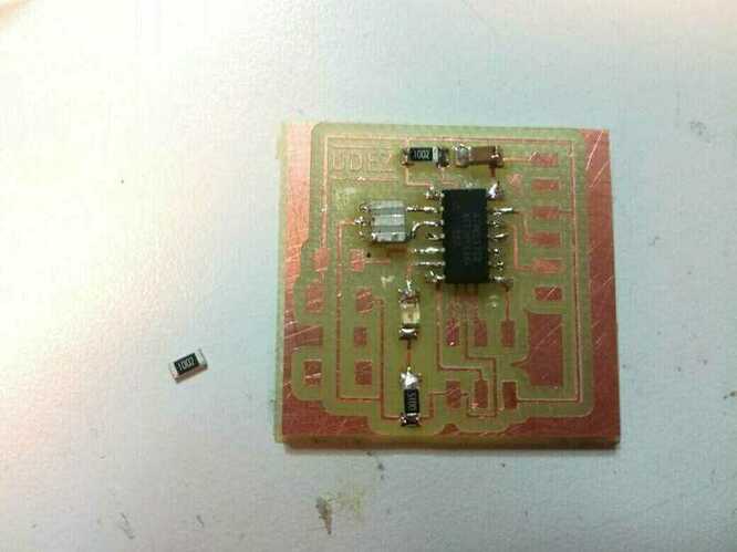
At the finish, I had some trouble with one of my solder join, so I use some flex, to remove the wrong connexions.
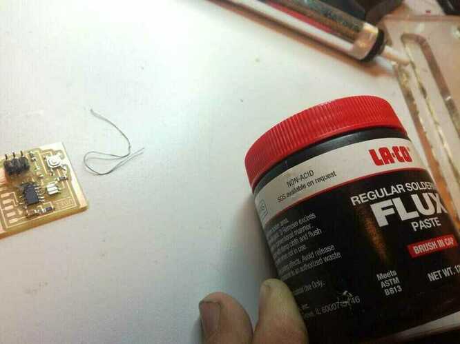
I didn't clean perfectly my board after then I applied the flux.
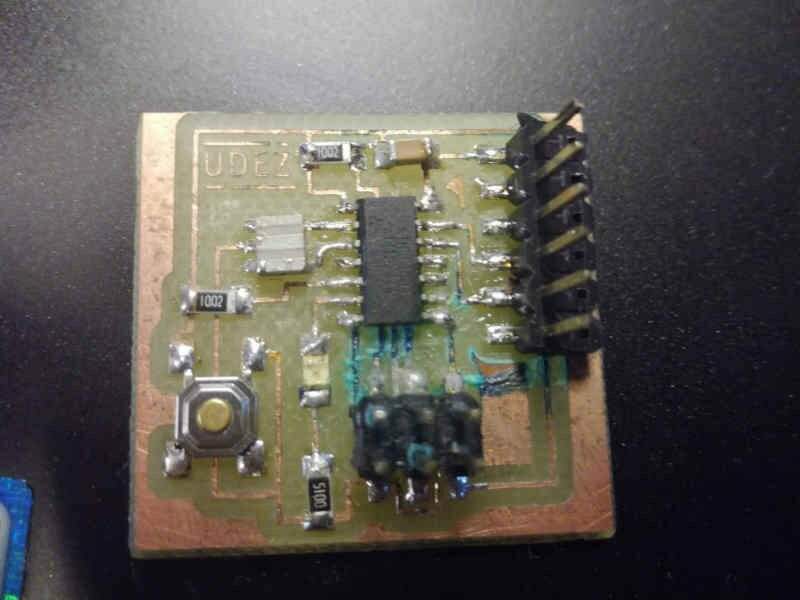
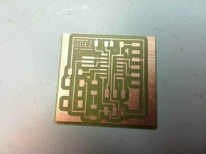
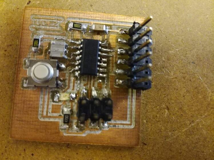
And here you can see the second board that I maid because this one in bellow as a shor circuit, and I broke it when I try to fix, so I remaid new one, using the same methodology:
Test the board
First electronic test
The first test, was to test if all the connexion are right with the multimeter. Some good tests:
- Check the good route to see if they are no problem
- Check randomly the connexions and look if it's normal
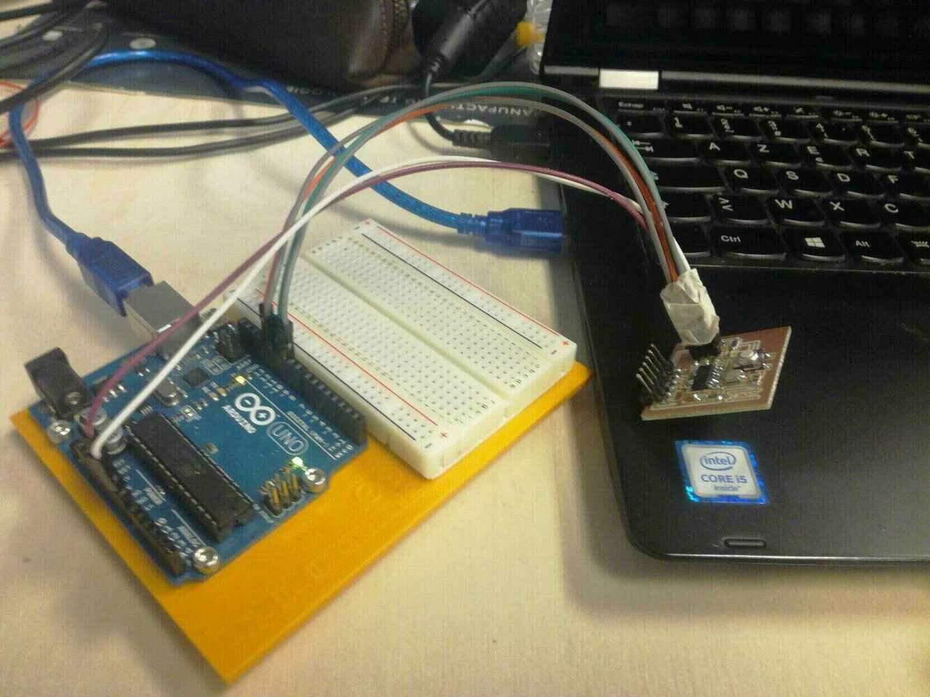
Upload the code with Arduino as ISP
Open the ArduinoISP firmware (in Examples) to your Arduino board.
Select the Board and Serial Port.
Upload the ArduinoISP sketch.
Wire your Arduino boards..

[Credit: Instructables]
Now your Arduino is an ISP
With the fabISP
I have some troubles with my FabIsp, I think they are problem in two resistances of my circuit board. I need to fix it 😦
How to solve it
Put an external alimetation with the FabISP, to be able to program the board.
Moreover, if you are a windows user, you need to install the USBTinyISP driver on windows.
Using the Arduino
So I decide to test the board with the arduino before fixing the FabISP.
The test code
#include <Arduino.h>

const int buttonPin = 6;     // the number of the pushbutton pin
const int ledPin =  7;      // the number of the LED pin

// variables will change:
int buttonState = 0;         // variable for reading the pushbutton status

void setup() {
 // initialize the LED pin as an output:
 pinMode(ledPin, OUTPUT);
 // initialize the pushbutton pin as an input:
 pinMode(buttonPin, INPUT);
}

void loop() {
 // read the state of the pushbutton value:
 buttonState = digitalRead(buttonPin);

 // check if the pushbutton is pressed. If it is, the buttonState is LOW:
 if (buttonState == LOW) {
   // turn LED on:
   digitalWrite(ledPin, HIGH);
 } else {
   // turn LED off:
   digitalWrite(ledPin, LOW);
 }
Tests result
- It works 😄
- I need to update my design to be synchronize with the arduino library
- Update the design to add more captors