17. Machine design
Actuate and automate the machine
About a week
During this week I would like to finish my work with the peristaltic pump. Before to start the electronics part, I finished the modeling of my peristatic pump. It was quiet hard, because, I lost 4 days during this week, because I was sick.
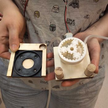
Modeling of peristaltic pump
I was so frustrated to be not able, to turn my pump. So I, order the right peristatic tube, but after some fails on my design and for the internet design that I found, I take one OpenScad script, and I adapt for what I had in the fablab, and I print all the pesitatic pump, in this case I don't use the bearings. For more information, please go in the mechanical design week
Electronics
Design the pcb
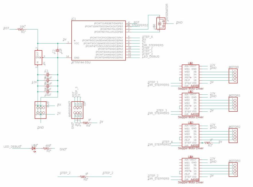
For my initial design, because, I'm using nema motors for my pump, I told that I will make 4 pumps for the machine. So I will use 4 drivers A4988, with an attiny84 on my board. So, I will need have 4 output pour the drivers , and 1 for the direction, he will be the same for all the stepper (I don't need to have the both directions). And also I decide also to add a led for the debugging.
When I tried, to make the routing, I saw that it will be more easy to make the rooting by adding one more pin direction for the drivers.
The final schematics:
One of the tried routing:
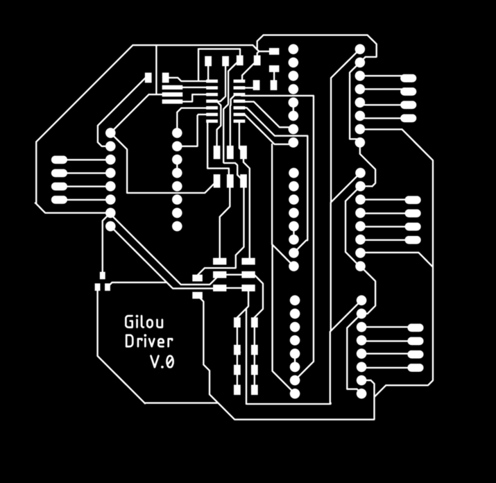
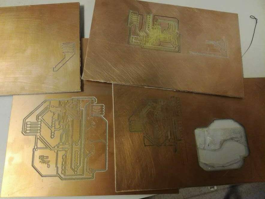
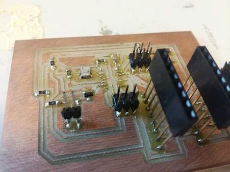
Make the pcb
Using mods, like the others week, I tried to make my board. I never try to make a board bigger than that. So i had so many troubles, I think our sacrificial board was not at the good level, so I was not able to produce it. So many try with any success. so frustrating.
Machining the Luc board
So, because I loose so much times with many reasons, I decide to try to made the board of Luc, and I was short in timing. The board does'nt work for me. I test all the parts with the multimetter, I don't show any errors, so I does'nt understand, I will ty to change the microcontroller. When I changed the attiny84 I was able to upload the code on the board.
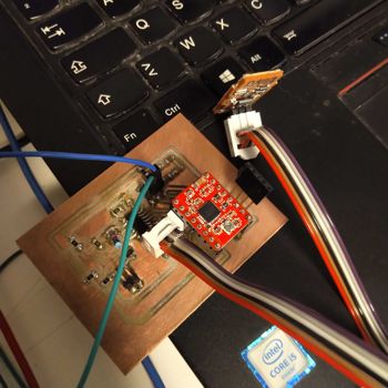
And then, taking his code to adapte it for my pump. Luc has the good board forme because I was not sure if I use a stepper or a DC motor. Finally I taked the dc motor, so it's a good thing to have to both possibilities.
So here is my code, I really respect the protocole that we defined with the group, I also maid a routine for the pump execution (pump_execute(byte motor, int value, int pumping_time)), the idea is to to manage many pumps, with only one function in the future.
So, here, there is the code for the first version of the machine :
// Code based on the work group
// to test pump at a speed of 20 , send 98 21 20 99
// to test pump 1 at a speed of 100 , send 98 21 100 99

#include <SoftwareSerial.h>

#define step_command 2 // PA2 _ 2 in Arduino
#define dir 3 // PA3 _ 3 in Arduino
#define motor_1 7 // PA7 _ 7 in Arduino

//TX , PA1 , Arduino 0
//RX , PA0 , Arduino A1

SoftwareSerial mySerial(A1, 0); // RX, TX

// address from 40 to 49
const byte code_start = 98;// code début : 98
const byte code_stop = 99;// code fin : 99
const byte code_confirm_receipt = 100; //100 accuse reception
const byte code_action_finished = 101; //101 fin d'operation
const byte code_ready_for_action = 102; //102 préparé
const byte adresse_pump1 = 21;

char received = 0;
byte decoded[3] = {1,2,3};


// specific pump
int pumping_time = 20; // 0 seconds

void setup() {
  pinMode(motor_1, OUTPUT);
  mySerial.begin(9600);
}

void loop() {

  lecture_reseau();

  if(decoded[0] == adresse_pump1 && decoded[1] != 0){
    //mySerial.print("motor_1");mySerial.println(decoded[1]);
    // confirm the reception
    mySerial.write(code_start);mySerial.write(adresse_pump1);mySerial.write(code_confirm_receipt);mySerial.write(code_stop);
    pump_execute(motor_1, decoded[1], pumping_time);
    mySerial.write(code_start);mySerial.write(adresse_pump1);mySerial.write(code_action_finished);mySerial.write(code_stop);
    // finished action
    reset_buffer();
  }
}
void waitSerialAvailable(){
    while (mySerial.available() == 0) {
        delayMicroseconds(1);
    }
}

void lecture_reseau(){
    if (mySerial.available()) {
        received = mySerial.read();
        if(received == code_start) {
            //mySerial.println("code start");mySerial.print(received);
            waitSerialAvailable();
            if (mySerial.available()) {
                decoded[0] = mySerial.read();
            }
            waitSerialAvailable();
            if (mySerial.available()) {
                decoded[1] = mySerial.read();
            }
            waitSerialAvailable();
            if (mySerial.available()) {
                decoded[2] = mySerial.read();

                if(decoded[2] != code_stop ){
                    reset_buffer();
                }
            }
        }
    }

}

void reset_buffer(){
  decoded[0] = 0;
  decoded[1] = 0;
  //mySerial.println("reset buffer");
}

void pump_execute(byte motor, int value, int pumping_time){
    analogWrite(motor, value);
    delay(pumping_time * 1000); // time pumping
    analogWrite(motor, 0);
}
Here we saw how the motor turn, I missed to take a nice video, but during the video he's connected to the board, just in left:
For more information, please go in the group page.